Language selection

Search

Patent 1304104 Summary

Third-party information liability

Some of the information on this Web page has been provided by external sources. The Government of Canada is not responsible for the accuracy, reliability or currency of the information supplied by external sources. Users wishing to rely upon this information should consult directly with the source of the information. Content provided by external sources is not subject to official languages, privacy and accessibility requirements.

Claims and Abstract availability

Any discrepancies in the text and image of the Claims and Abstract are due to differing posting times. Text of the Claims and Abstract are posted:

  • At the time the application is open to public inspection;
  • At the time of issue of the patent (grant).
(12) Patent: (11) CA 1304104
(21) Application Number: 1304104
(54) English Title: TOW HITCH SYSTEM
(54) French Title: ATTELAGE
Status: Term Expired - Post Grant
Bibliographic Data
Abstracts

English Abstract


ABSTRACT OF THE DISCLOSURE
A tow hitch system comprising a tow bar to be
secured to a towing and to a towed vehicle. The towing
vehicle includes spaced openings adjacent to the point
where the tow bar is secured. There is an anchor point
on the tow bar. A chain received at the anchor point. A
pair of safety catches at each end of the chain engage
the spaced openings. Each safety catch comprises a
central limb to be received in an opening. Side limbs
extend from each end of the central limb to contact
opposed sides of an area of the towing vehicle adjacent
the point where the tow bar is secured to maintain the
catch in position. The system is easy to make and very
easy to use yet safe in use.


Claims

Note: Claims are shown in the official language in which they were submitted.

47355
-7--
THE EMBODIMENTS OF THE INVENTION IN WHICH AN EXCLUSIVE
PRIVILEGE OR PROPERTY IS CLAIMED ARE DEFINED AS FOLLOWS:
1. In a tow hitch system comprising:
a tow bar to be secured to a towing and to a towed
vehicle, the towing vehicle including spaced openings
adjacent the point where the tow bar is secured, the
improvement comprising:
an anchor point on the tow bar;
a chain attached to the anchor point at a point
intermediate the ends of the chain;
a pair of safety catches, one of said pair of safety
catches at each end of the chain, to engage the spaced
openings;
each safety catch comprising a central limb to be
received in an opening and dimensioned for rotatable
movement in said opening;
elongated side limbs extending parallel thereto from
each end of the central limb to contact opposed sides of an
area of the towing vehicle adjacent the point where the tow
bar is secured to maintain the catch in position; and
an eye at one end of one of said side limbs of each
safety catch to receive the chain.
2. A safety device for a tow bar comprising:
at least one chain attached to the tow bar;
a safety catch attached to an end of said at least one
chain, the safety catch comprising:
a central limb;
two elongated side limbs, one of said elongated side
limbs extending from each end of the central limbs the
central limb being receivable and rotatable in an opening
in a towing vehicle with the side limbs extending to
contact the top and bottom of the area surrounding the
opening to maintain the catch in position.
3. A safety device as claimed in claim 2 in which there
is a single chain attached to said tow bar at a point

-8-
intermediate the ends of the chain with a safety catch at
each end of the chain.
4. A safety device as claimed in claim 2 including a
plate to be attached to the towing vehicle and having a
central ball joint attachment adapted to releasably engage
a tow hitch;
an opening at least one side of said ball joint
attachment to receive the safety catch.
5. A safety device as claimed in claim 4 including guides
on the plate to locate the tow bar.
6. A safety device as claimed in claim 4 in which there
are two openings, one of said openings on each side of the
central ball joint attachment.
7. A safety device as claimed in claim 2 having an eye at
one end of each side limb to receive the chain.

Description

Note: Descriptions are shown in the official language in which they were submitted.


~.3~
7355-1
TOW HITCH SYSTEM
This invention relates to a safety device for a
tow bar and to a tow hitch including the safety device.
The towing of trailers is well known. It is
done by all sizes of vehicles from family sedans towing
small camping trailers to large trucks increasing their
hauling capacity by towing large trailers.
The towing is carried out by a variety of means
including fifth-wheel hitches and tow bars, the latter
being generally preferred, certainly with small trailers.
All tow bars must have a safety device. If the
bar fails the safety device maintains the tow at least
until the vehicle can be stoppedv These safety devices
take many forms. Examples include those described in the
United States Patents 2,712,945 to Peterson; 3,125,355 to
Snuggins; 3,464,720 to Abromavage and 3,54g,173 to
Stanfield.
The above patents indicate clearly that chains
are much used in safety devices and the patents feature a
variety of methods of attaching these chains. In addi-
tion, attention should be directed to U.S. Patents
2,322,576 to Huebsham showing a hook structure for use in
a tie down device when a vehicle is being li~ted. U.S.
Patent 4,422,608 to Hogg features a hook, but the hook is
lightweight and attaches to a wall, for example for
-1- 3

~3~10~L
hanging picturesO Hogg is essentially a lightweight
structure including a pressure sensitive adhesive to
assist in the location on a surface.
The present invention seeks to provide a safety
device for use with a tow hitch system and to provide the
tow hitch system. The safety device of the present
invention is especially simple to use, easy to manufac-
ture yet effective in use.
Accordingly, in a first aspect the present
invention is a tow hitch ~ystem comprising a tow bar to
be secured to a towing and to a towed vehicle, the towing
vehicle including spaced openings adjacent to the point
where the tow bar is secured, the improvement comprising
an anchor point on the tow bar; a chain to be received at
the anchor point; a pair of safety catches at each end of
the chain to engage the spaced openings; each safety
catch comprising a central limb to be received in an
opening; side limbs extending from each end of the
central limb to contact opposed sides of an area of the
towing vehicle adjacent the point where the tow bar is
secured to maintain the catch in position.
In a further aspect the present invention is a
safety device for a tow bar comprising: a chain to be
attached to the tow bar; a safety catch attached to an
end of the chain, the safety catch comprising: a central
limb; a side limb extending from each end of the central
-2-

limb, the central limb being receivable in an opening in
a towing vehicle with the side limbs extendin~ to contact
the top and bottom of the area surrounding the opening to
maintain the catch in position.
Desirably there is a safety catch at each end
of the chain. The safety device can attach to the bumper
of a small truck, which may be adapted, as necessary, to
receive the safety device. In addition, par~icularly for
use with cars, the device may include a plate having a
central position to receive a ball joint of a tow hitch
and an opening at least one side of the central position
so that the safety device of the invention can be
attached. Such a plate is attached to a structure of a
car in conventional manner for a towing ball joint.
In a preferred aspect the plate has guides to
locate the tow bar.
Aspects of the invention illustrate~, merely
by way of example, in the accompanying drawings in which:
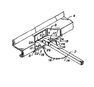
Figure 1 is an isometric projection of a tow
hitch system according to the present invention;
Figure 2 is a detail, partially in section, of
Figure l; and
FLgure 3 illustrates a detail of a particular
embodiment of the invention.
Figure 1 shows a tow hitch comprising a -tow
bar 2, of ~onventional configuration, secured to a towing

~3~0~
vehicle, the rear bumper 4 of the towiny vehicle only is
shown. The bar 2 is also attached -to a towed vehicle in
an entirely conventional manner. The towed vehicle is
not shown. The illustrated bumper 4 in Figure 1 is con-
ventional and includes a recess 6 having a plate 8
attached. This recess 6 and plate 8 acts as a step to
enter the vehicle or, of course, for the attachment of
the tow bar 2. Al-though not shown in Figure 1 a ball
joint extends through the center of the plate, the ball
joint as being shown in Figure 3 at 10.
There are spaced openings 12 on each side o
the ball joint 10. There is an anchor point 1~ on the
tow bar 2. Anchor point 14 is shown as an eye but may
simply comprise welding of safety chain 16 to the tow
bar 2. Chain 16 is received at the anchor point 14.
A pair of safety catches 18 are positioned at
each end of the chain 16 to engage the openings 12 in the
tow plate 8. 'Fhis is shown in particularly in Figure 2.
Each safety catch 18 comprises a central limb 20, to be
received in the opening 12. Side limbs 22 and 24 extend
from each end of the central limb 20 to contact the top
and bottom of the tow plate 8 to maintain the catch 18 in
position. The arrangement is shown in Figure 2.
In the preferred embodiment illustrated there
are safety catches 18 at each end of the chain 16. This
is much preferred although there may be circumstances

~L3~)4~
where only one safety catch 18 is needed~ As indicated
in Figures 1 and 2, each safety catch 18 is formed with
an eye 2~ to enable attachment of the chain 16. As shown
particularly in Figure 2 the opening 12 is such that the
limb 22 and the limb 20 can be fed through the opening
12. The central limb 20 is then retained in the opening
12.
The device of the present invention is ex-
tremely simple to use. In the preferred embodiment, in
which the anchor on the tow bar 2 is a simple eye, one
sa~ety catch 18 on the chain 16 is fed through the eye.
The safety catch 18 is then arranged generally vertical
to the opening 12 pushed downwardly and turned through
90. It is then loosely held in the opening 12, as shown
in Figure 2, but it cannot be disturbed by simple vibra-
tion. It can only be removed by a positive action taken
by an individual turning the safety catch through 90D SO
the lower limb 22 can pass through the opening 12 to
release the safety catch from the tow plate. The second
safety catch 18 is then engaged in the other opening 12.
~ s will be appreciated the attachment of these
safety catches takes mere seconds.
Thus to attach the safety system it is simply
necessary to make the tow hitch in conventional manner,
typically by placing bar 2 over the ball ioint 10,
attaching the trailer, all in conventional manner, and

~L31C~4~
then attaching the safety devices to the openings 12 in
the -tow plate 8 as desicribed above.
Figure 3 illustrates a modification to the
invention in which conventional ball joint 10 is attached
to the frame of a car by a bar 26. A plate 28 extends
outwardly from the ball joint 10 and is provided with
openings 12 to be engaged by the safety ca~ches 18. In
the embodiment of Figure 3 there are guide surfaces 30 to
receive and locate the tow bar but these are not essen
tial to the invention.
The present invention may be made of mild
steel. Where appropriate heavy-duty material may be used.

Representative Drawing
A single figure which represents the drawing illustrating the invention.
Administrative Status

2024-08-01:As part of the Next Generation Patents (NGP) transition, the Canadian Patents Database (CPD) now contains a more detailed Event History, which replicates the Event Log of our new back-office solution.

Please note that "Inactive:" events refers to events no longer in use in our new back-office solution.

For a clearer understanding of the status of the application/patent presented on this page, the site Disclaimer , as well as the definitions for Patent , Event History , Maintenance Fee  and Payment History  should be consulted.

Event History

Description Date
Inactive: Expired (old Act Patent) latest possible expiry date 2009-06-23
Inactive: Entity size changed 2002-06-10
Grant by Issuance 1992-06-23

Abandonment History

There is no abandonment history.

Owners on Record

Note: Records showing the ownership history in alphabetical order.

Current Owners on Record
ARTHUR LIKEI
Past Owners on Record
None
Past Owners that do not appear in the "Owners on Record" listing will appear in other documentation within the application.
Documents

To view selected files, please enter reCAPTCHA code :


To view images, click a link in the Document Description column (Temporarily unavailable). To download the documents, select one or more checkboxes in the first column and then click the "Download Selected in PDF format (Zip Archive)" or the "Download Selected as Single PDF" button.

List of published and non-published patent-specific documents on the CPD .

If you have any difficulty accessing content, you can call the Client Service Centre at 1-866-997-1936 or send them an e-mail at CIPO Client Service Centre.


Document
Description 
Date
(yyyy-mm-dd) 
Number of pages   Size of Image (KB) 
Abstract 1993-11-01 1 18
Cover Page 1993-11-01 1 11
Claims 1993-11-01 2 60
Drawings 1993-11-01 1 29
Descriptions 1993-11-01 6 171
Representative drawing 2001-11-29 1 10
Fees 2003-06-10 1 36
Correspondence 2001-05-21 1 30
Fees 2002-05-22 1 39
Fees 2004-05-31 1 44
Fees 2005-06-02 1 40
Fees 2006-05-30 1 36
Fees 2007-05-22 1 36
Fees 2008-05-22 1 36
Maintenance fee payment 1996-02-04 1 42
Maintenance fee payment 1995-06-11 1 39
Maintenance fee payment 1994-05-18 1 35