Note: Descriptions are shown in the official language in which they were submitted.
~ 3~ 2~3
PA~I~L Dr;VICE
This invention is concerned with por-table, flexible, panel derices which
can be used to display information a-t trade shows and conventions. The panel
device of this invention is also useful in the furniture arts. Panel devices
as may be used at trade shows or conven-tions are oF two principal -types,
these being the large bulky type and the portable type. This invention is
concerned with the portable type of display device. The portable display
devices have become very popular in recent years for utilization at regional
trade shows and conventions. These portable display devices, when assembled,
present a nice impression and have a very high display surface to weight
ratio. Further, these portable display devices are advanta~eous in that
they can be quickly and easily assembled and disassembled without tools by
one person. In contrast, the large bulky display devices as mentioned above
are very heavy and hence have a low display surface -to weigh-t ratio. ~urther,
thase display de~ices can he assomblacl alld disassal~ lacl only wi~ a,~lt
difficulty by extra wor~men at great expense.
The subject invention is useEul in connection with por-tahle d.isplay
devices wherein a plurality of cisplay panel~s are a-ttached to channels which
in turn funetion as supportin~ means. It is often des~rable to locate -the
panels of a display device in angular relationship with each other. It is
in this area where the sub~ect invention is useful. In accord~nce with this
invention the panels of the device of this invention ean he located in any
desired relationship with each other over a 360~ are.
This invention also includes the connector system which is useful in
holding component parts of a display device in fixed relationship wi-th each
other. Also included in this invention is a vertical support and related
double hinge system which allows the panels of the composite structure to
rotate in relation to each other over a 360 arc. The invention is also
concerned with a unique hinge system which allol~s rotation through a 360
arc.
la
~.3~4L2~3
Accordingly, the invention provides a device comprising
a plurality of vertical supports, adjacent vertical suppoxts
being pivotally attached to each other by double hinge members,
said double hinge members comprising at least two clip hinge
elements, the clip hinge elements having a main body portion
and 180 opposing attaching members and locking tabs integral
with the attaching members, the vertical supports having
integral means for receiving the integral attaching members and
locking tabs of the clip hinge elements, panels being secured
between non-adjacent pairs of vertical supports.
The invention also provides a vertical support which
is useful in a device for securing panels, the vertical support
having an elongated body portion and a cross section which has
a central U-shaped channel which is flanked on opposite sides
by a pair of second U-shaped channels wherein the vertical
support opposite of the openings of the U-shaped channels is
arcuate.
JJ ib
JAN 24 199~
~ 3~%~3
DESCRIPTI0N OF Tli~ DRAWINGS
Figure 1 is a front view showing a section of the subject panel device.
Figure 2 is an end view along line 2-2 of Figure 1 showing the vertical
supports of the panel device in parallel relationship with each other.
Figure 3A is a top sectional view showing the two panels in parallel
relationship to each other.
Figure 3B is a top sectional view showing two panels in a straipht line
relationship with each other.
Figure 3C is a top sectional view showing two panels in parallel
relationship with each other opposite of that sho~m in Fif~ure 3A.
Figure 4 is a cross section along line 4-4.
Figure 5 is a perspective view showing the clip hinge element o~ this
invention .
Figure 6 is a perspective view showing the placement of a pair of
hinges on a pair of vertical supports.
Figure 7 is a side view showing the panel device of this invention where.in
three panels are interconnected.
Fi,gure 8 is a top view of the three panel structure of Figure 7.
Figure 8A is a top view of the three panel structure of Figure 7 in
angular relationship.
Figure 9 is a perspective view showing the interconnecting of hori~ontal
and vertical members with a connector plug.
Figure 9A is a perspective view showing the CooPerat;.On of the
horizontal member with a panel~
Figure 10A is a top view showing two panels in a parallel line
relationship with each other wherein the panel is secured by edge plies.
Figure 10B is a top view showing two panels in a straizht line relationship
with each other wherein the panel member is secured by edge plies~
Figure 10C is a top view showing two panels in parallel relationship
with each other opposite of that shown on Figure 10A wherein the panel is secured
by edge plies.
Figure llA is a cross section of the preferred embodiment of a vertical
support which is useful in; this invention.
~.3~ 3
Figure llB is a cross sect;.on of a simplified ernbodiment of a vertical
support.
Figure llC shows another embodiment of a vertical support.
Figure 12 is a perspective view showing means whereby the fabric covering
of the panel can be wrapped around the panel device components.
Figure 13 is a cross sec-tion view oE a horizontal support.
Figure 14 shows the connecTion oE two panels and related vertical
supports in fixed relationship with each other.
Figure 15 is a perspective view showing a connector plug for connecting
two panels in fixed relationship with each other.
Figure 16 is a top plan view showing the connection of a plurality of
vertical supports and related panels.
Figure 17 is a front view of an embodiment of a panel device in accordance
with this invention showing means for displaying panel indicia
Figure 18 is a perspective view showing the placement of indica in the
panel device of Figure 17.
Figure 19 and 20 are side views showing the means ~or incorporatinY~ additional
panels into the panel device of this invention.
Figure 21 is a side view showing a leg structure for use with this invention.
Figure 22 is a perspective view of a notched vertical support.
Figure23A and 24 are side views showing notched vertical supports.
Figure 23B is a section view through line 23B of Figure 23A.
Figure 25 is a perspective view showing an alternate clip hinge element
structure.
Figure 26 is a perspective view showing the placement of a pair of clin
hinge elements as shown in Figure 25 onto a pair of vertical supports.
Figure 27 is a cross section vie-;r showing the placement of the alternate
clip hinge structure of Figure 25 in vertical supports..
~3~ 3
DE;SCRIPTIOI`~ OF THE PR~:FERRED E~qBODIMENT
-
The subject invention relates to a panel device which comnrises a
plurality of vertical supports which are secured in parallel relationship
with each other with a plurality of s-trap double hin.~7,es. Spaced between the
vertical supports are panels. The parallel relationship oF the vertical
supports may be further deEined by interconnecting hori~ontal supports. 1'he
combination of the vertical supports and horizontal supports define a frame
which may be square or rectangular. Secured within each frame so defined is
a panel member.
As is mentioned hereinabove the subject panel device is p.~rticularl~
useful in the portable display art, It sho~ld be noted however that the
panel device of this invention is also useful in the Eurniture art. The
subject panel device can be fabricated in such a size that it can be used
for example as a room devider, o:Ffice seperator, privacy screen or noise
barrier, In the furniture arts the panel device at hand is particularlv
useful in that the various pane].s can be angularly disposed in relation to
each other to define any given surface area, IE so desired these panel
members can be locked into relationship with each other,
Referring to Figure 1 it can be seen that tl)e panel device of this
invention 2 comprises a pair of vertical supports 4 and fi, a pair of
hori30ntal supports 8 and 10 and a panel 12.
As is shown in Figures..land 2, pairs of ad-Jacent vertical supports 6
and 14 ars rotatably connected to each other via a plurality of clip hin~7,e
elements 16, 18, 20 and 22, These clip hinge elements coopera-te with and
grip the vertical supports in a manner which will be described hereinbelo~l.
Figures 3A, 3B and 3C illustrate how related panel devices can be
rotated through a 360 arc in relation to each other, In Figure 3A it can
be seen that into vsrtical supports 6 and 14 are secursd panels 12 and 24.
In this Figure panels 12 and 24 are in parallel relationship with each
other, In E'igure 3B vertical support 6 has been rotated in the direction
of arrow 26, As a result of this rotation,panels 12 and 24
are now in a straight line relationship with each other.
In Figure 3C the rotation of vertical support 6 in relation to
vertical support 14 is continued in the direction oF arrow 28,
~.31~L2~3
l~pon completion of rotation in the direct;on of arrow 28 panels 1.? and
24 are again in parallel relationship with each other. In comparin~ Fi,c~ure
3A to Figure 3C it can be seen that panel 12 has been rotated 360 in rela~ion
to panel 24~ It is understood by one skilled in the art that th.is rotation
of panels 12 and 24 in relation ~o each o-ther could be stopped at any point
to achieve any desired angular relationship of panels 12 and 24.
Vertical supports 6 and 14 incorporate a plurality of inte~ral lips 80,
32, 34 and 36. Panels 12 and 24 are scored in such a manner that lips 30,
32, 34 and 3~ are adapted -to grip said scored portion.
Panels 12 and 24 may be formed from a material which ma~ he readily
scored such as a foam board. The manner in which panels 12 and 24 mav be
scored and positioned in vertical supports 6 and 14 and gripped by lips
30, 32, 34 and 36 is described in detail in U.S. Patent 3,~;62,807 issued
~ay 16, 1972.
The rotation .,f panels 12 and 24 and vertica} supports 6 and lL~ is made
possible by the fact that adjacent vertical supports 6 and 14 are inter-
connected with each other by two or more double hinges which comprise
clip hinge elemen t 16, 18, 20 and 22.
Figure 4 is a section ta~cen along line 4-4 of Fi~ure 1. In this fixure the
attachment oE the second clip hinge element ~o to vertical suppor~s ~ and l
can be seen.
From Figure 6 it can be seen that a composite hinge 35 consists of a pair
of clip hinge elements 18 and 20. It can further be seen that clip hin~e
elements 16 and 20 can be easily slipped on to vertical supports 6 and 14.
The structure of clip hinge element 18 can be further seen from an
examination of Figure 5. Clip element 18 comprises a main body portion 37
which is formed from a suitable flexible material and a pa.ir of opposin~ end
portions 40 and 42. End portions 40 and 42 comprise reverse b~3nqs, In order
to interlock with adjacent vertical supports and stay in tension during rotation
the reverse bends of end portions 40 and 42 must be opposite o.f each other. (~
hinge element 18 may be formed from any suitable flexible material such as a metal
or polymeric material. For example, clip hinge element 18 can be lorrned from a
thermoplastic polymeric waterial such as a poly alpha ole.;in. I~ clip hinl~,e 18
is formed from a thermoplastic rnaterial, reverse bend end portions can be 'ormed
by a thermal bendin~ process. A clip hinge element complete with reverse bend
end portions may also be i'ormed by injection molding.
~3~ 2~L3
Clip hinge element 18 can likewise be formed from a metal with reverse
bend end portions being Eormed from a precut section of metal by a suitable
bending process. If a thermoplastic material is used, it has been found that
for portable display devices a width of approximately .S inches and a thic~-
ess of about .030 inches is desirable. The clip hinge elements may beto three Eourths hard
formed from a metal. Half hard~stainless steel is the prefarred metal for
use in accordance with thls invention. The clip hinge element should have
a width oE approxirnately .5 inches and a thickness of approximately .007 inches.
In the preferred embodiment half hard .007 inches thick 304 stainless steel
is utili~ed.
As is il.lustrated in Figure 6 each end of a pair of vertical supports
6 and 14 utilize a pair of clip hinge elements 18 and 20. The opposite end
of said pair o~ vertical supports also utilize a pair of clip hinges not
shown, Pairs of hinges are utilized as during rotation in relatioD to each
other over 360 stress is alternately applied and released to cooperating
clip hinge eler~ents 18 and 20 depending on the respective position o~
vertical supports 6 and 14.
Any member of composite structures 2 can be interconnected in series
in order to produce a display device of the desired size. Likewise three
or more composite panel devices can be interconnected if it is desired to
have a panel device in which the three or more panels can rotate in relation
to each other. As can be seen in Fi~ures 7, 8 and 8A, three composite panels
38, 40 and 42 are booked together. These composite panels consist of three
vertical supports 44, 46 and 48. These vertical supports are interconnected
by four clip hinge elements S0, S1, 52 and 54. ~.7ith this structure,cornposite
panels 38 and 42 can be ro-tated in relation to central panel 40 in the
direction o~ arrows 56 and 58,
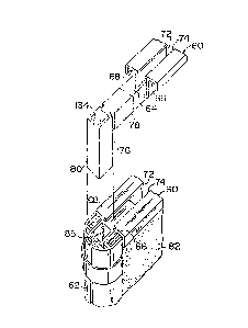
Figure 9 illustrates one ernbodiment of a hori~ontal support 60 and the
attachment of this 'norizontal support to vertical support 62. Horizon-tal
support 60 incorporates U-shaped sections 64, 66 and 68. As is
illustrated, the open and o~ U-shaped sections 66 and 68 are opposite the
open end of U-shaped section 64. U-shaped section 64 ~urther incorporates
a pair o~ opposing lips 72 and 74. In order to connect horizontal support 60
to vertioa} support 62 a connector plug 76 is inserted into the aperture
which is defined by U-shapod ahannel 64 and lips 72 and 7L~ and secured tberein
with a mechanical Eastener or an adhesive The opposite end 80 o~ connector
plug 76 is in turn inserted into aperture 85 of vortical support 62.
~.3~ 3
Further from Figure 9 and sA it can be seen tha-t hori~ontal supDort 60
is adapted to engage panel 82 via U-shaped channels 66 and 68, Panel 82
comprises a central core 81, for example a honeycomb core, and a pair of outer
plies 83 and 87. The core 81 is cut or crushed inwardly to the depth oE
U-shaped channel 64, outer plies 83 and 87 of panel 82 may then be inserted
into U-shaped channels 66 and 68, In -this manner it can be seen that
horizoDtal support 60 and panel 82 are securely interconnected. Likewise
horizontal support 60, vertical support 62 and panel 82 are securely inter-
connected to each other to form a strong, unitary panel device.
Figures lOA, and lOB and lOC further illustrate how panels and related
horizontal and vertical supports may be rotated in relation to each other.
In these figures panels 84 and 86 are rotated 360 in relation to each other
in the direction of arrows 88 and 90.
An integral part of the subject invention is the vertical support system
the function of which has been described hereinabove. In its sirnplest
embodiment in accordance with this invention the individual vertical supports
must incorporate a means for engaging the clip hinge elements and a means
for engaging panel members, Suitable vertical supports are illustrated in
Figures llA, llB and llC.
Figure llA illustrates the preferred embodiment of a vertical support
or use in this invention, In this structure vertical support 142 incorporates
or channel
a oentral U shaped opening/144 which is defined by sides 146 and 148 and a
bight 150. This vertical support also incorporates a pair of U-shaped channels
152 and 154, U-shaped channel 154 is defined by sides 146 and 156 and
bight 162, Conversly U-shaped channel 152 is defined by sides 148 and 158 and
bight 160, The reverse bends of the clip hinge elements as are illustrated
in Figure 5 en~agc sides 156 and 158 of vertical support 142, Vertical support
142 further incorporates a pair of lips 164 and 166 which further define
U-shaped opening 144, Lips 164 and 166 are adapted to en~age score lines
which are an integral part oE the panel portion not shown in a manner as described
herein above, The rear portion of vertical support 142 incorporates an
opening 168 which is defined by le~s 170 and 172, Legs 170 and 172 in turn
incorporate a pair of opposing lips 174 and 176, Opening 168 is useful in
that vertical support 142 may be covered with a fabric, This fabric is tucked
around the leading edge of sides 156 and 158 behind the reverse bend section
o~ the strap hinge element, The opposite end of the oovering fabric is
tucked into opening 168 and secured via lips 174 and 176,
~ 304~
Figure llB represents the simplest form of a vertical suppor-t which
rnay be used in accordance with this invention. In this embodiment vertical
support 136 comprises a section of tubine which has part of its circumference
cut away in such a manner that lips 138 and 140 are formed. The openin~ 142
which is defined by lips 138 and 140 is adapted to receive a panel member
in the manner as descr.ibed hereinabove~ The reverse bends of the embodiment o~
clip hinge element illustrated in ~igure 5 is adap-ted to slip around lips
138 and 140.
Figure llC illustrates still another embodiment of a vertical support. In
this s-tructure vertical support 62 cornprises a half round extrusion havin~ a
central U shaped opening 85 whicll is defined by sides 112 and 114, and by bi~hts
116 and 117, Lips 113 and 115 further define U shaped opening 85. Suitable
clip hinge elements can engage lips 113 and 115 and a sui-table panel member can
be positioned in U shaped opening 85 between lips 113 and 115.
Accordingly, it can be seen that if desired a plurality of vertical supports
may be used in a manner as was described in reference to Figure 1, 2 and 6
hereinabove.
Vertical and Horizontal supports as described may be formed from any
convenient material. These supports may be extruded from a thermoplastic material
such as a polyalpha olefin or a nylon. In the preferred embodiment these elemen-ts
are aluminum extrusions which are extruded from aluminum. Cosmetics and color
combinations are very important in displaying devices which are used at trade
shows. In this connection vertical and horizontal supports may be colored or
painted to achieve any desired effect. If colored vertical and or horizontal
supports are desired in the preferred embodiment this coloring is achieved by
anodizing cr painting of the aluminum extrusions.
Figure 12 illustrates a panel device in accordance with this invention
wherein both the vertical and horizontal supports are completely covered with a
fabric. In this embodiment fabric is rolled around vertical support 142. One
end of the fabric is tucked into opening 168, the other end of the fabric is
tucked around the edges of sides 156 and 158 as was described in connection with
Figure l~A.
Panel 178 comprises a central core 180 and a pair of opposing plies 182
and 184. Pl;es 182 and 184 are biased into and seoured in U shaped channels 152
and 154 by the biasing of the reverse bend portion of clip hinge element 186.
~3~2~3
In this instance horizontal support 188 is ll-shaped and has a central openinv,
190 which is deEined by sides 192 amd 19ll, biy,ht l9G and lips l~)B and 200. I'al~r;.c
layer 202 covers ply 182 and is tucked around the oppermost ed~e 204 of
ply 132 and between side 194 of horizontal support 188 and ply 182. Horizontal
support 188 and ver-tical support 142 can be interconnected via a connector plug
such as plug 76 as is described above in connection with Fi,gure 9.
The strueture of Figure 12 is advantageous in that if a plurality of panel
deviees are staeked on top of each other both the horizontal and vertical supports
are fully covered with fabric 202, in such a Tnanner as to present a very pleasin
and uniform appearance.
Figure 13 shows in greater detail partieulars of horizontal suDport 60.
~lorizontal support 60 incorporates a pair of l~-shaped channels 66 and 68.
Channels 66 and 68 are adapted to reeeive the outer plies 83 and 85 of panel 82
as has been deseribed hereinabove in conneetion with Figures 9 and 9A. Horizontal
support 60 further ineorporates a pair of opposing lips 72 and 74. ~)pposinv lips
72 and 74 are adapted to engage connector plug 76 as is shown in Figure 9.
While the panel device of this invention is very desirable in that the
panels can be moved through a 360 arc after movement in sorne usaY,e it is
desirable to lock a plurality of panels in fixed relationship with each other.
One mode of locking panels in relationship with each other is illustra-ted in
Figure 14, In this embodiment two panels 207 and 208 incorporate horizontal
supports 210 and 212 ~1hich are identical to horizontal support 60 as descri.bed
above in reference to Figures 9 and 9A. Horizontal supports 210 and 212 are
connected to vertical supports 214 and 216 via a pair of connector plugs not
sbown. Referring to Figure 9 it ean be seen that the vertieal leg of connector
plug 76 is hollow and incorporates a scuare apeture 134 whieh is analoF~ous to
apetures 218 and 220 as is illustrated in Figure 14. Panels 207 and 208 are
secured in fixed re~ationship with each other by placing a lockinF, plug 222 into
apetures 218'and 220. The details of locking plug 222 are better illustrated
in Figure 15. Loeking plug 222 incorporates a pair of square do~mward depending
legs 224 and 226. When legs 22L~ and 226 are plaeed into apeture 21B and 220
panels 210 and 212 are secured in fixed relationship with each other. That is
because the spaeing of legs 224 and 226 i5 fixed, the spaeing of apeture 218 and
220 is in turn fixed which in turn fixes -the relationship of panels 207 and 208.
While legs 224 and 226 and corresponding apetures 218 and 220 are il.lus-tra-ted
as sq,uaro it ls understood by one slc.ill.ed ;n ~he art ~hat these colnponent~; ccul~
be round or an~ eonvenient shape.
~.3~ 3
~ igure 16 illustrates still another embodiment of this invention wherein a
plurality of panels can be locked into position with each other.
As was described in reference to Figure llA vertical support lL~2 incorporates
an opening 168 which is adapted to receive the ends of fabric which is used to
cover the vertical suppor~. Figure 16 illustrates a composite panel device 223
which incorporates three panels 22~ 226 and ~28 and three vertical supports
230, 232 and 234. These vertical supports in turn have as an integral part ~hereof
openings 236, 238 and 240. In order to lock panels 224, 226 and 228 of composite
panel device into a fixed relationship with each other a lockin~ plu~ 242 is
inserted into openings 236 238 and 2LlO.
Locking plugs 222 and 242 as are described in reference to Figures lS and 16
can be formed from any convenient material such as a metal or a polymeric material.
In the preferred embodiment these plugs are injec-tion molded :From a durable
thermoplast::;c such as a poly alpha olefin or a nylon. Figures 15 and 16
lllustrate the locking of two and three panels together it is understood that
any convenient number of panels can be locked together.
Figures 17 and 18 illustrate an embodiment of this invention wherein a display
device 248 can be used to protect and display larse sheet items such as
photo~raphs. ~isplay device incorporates a pair of opposin~ vertical supports
~S0 and 252 which may be connected to additional adjacent vertical supports
not shown, in a manner as described hereinabove. In this structure a horizontal
support positioned over the top edge of panel 256. sides 258 and 260 oF U shaped
horizontal support 254 are:positioned downwardly over panel 256. The upper
edge of panel 256 is positioned in and gripped by lips 262 and 264 of vertical
support 254. With this positioning a space exist between side 260 of horizontal
support 254 and side 266 of vertical support 250. This space is adanted to
receive an indica sheet 268 which may be a poster or a photo~rar?h and a ~ransparent
protective sheet 248. By usin~ this structure inexpensive art ~lork such as a
photo~raph can be readily displayed and chan~ed at ease in the display device
of this invention. The cornposite structure may then be covered by a cap channel
251 which is held in place with clips 253 and 255
Figures 19 and 20 illustrate an embodiment of this invention wherein a
cantilever header may be placed on a panel device. In this structure vertical
support 2a2 is adapted to receive and support panels in a ~nanner ~s described
herein above. A cantilever header iS formed by the connection o.F a sect~on 284
~3~
oE the extrusion, which is used -~o ~orm rhe vertical :,upport, -to ver~ical .~upport
282 by use of a connec-tor brace 26G, Lcp,s 233 and 280 o~ connector ))rac-:
286 are positioned in opening 163 as is shown and described herein above in
connection with Figure llA. By use of this structure a section 28~ and an
opposing identical section on the next adjacent vertical support not shoim,
can be used to form a cantilever header. To ~orm said header a panel is secured
in sec-tion 284 and its adjacen-t counterpart.
Figure 21 illustrates an embodiment ~herein a leg support 292 rnay be added
to the panel device of this invention in order -to Kive it greater lateral
support. Leg support 292 comprises a base sec-tion 294 and a connector leF~ 296,
A screw locked stop 298 is secured to connector leg 296, Connector leg 296
is positioned in vertical support 300 i.nto opening 144 which is illustrated
and described in detail herein above in connection with Figure llA,
Fi~,ures 22, 23A, 233 and 24 illustrate modifications o~ the edges oE vertical
support 302 and 304, As was described above in re~erence to Fi,yures S antl 6 the
clip hinge elements ~Irap around and engai~e thc outer edge of ~he vertic,ll support.
In order to prevent the clip hinge elements Erom moving on vertical supports
302 the outer edges of this vertical support can be notched as per no-tches 306 and
308, In operation the bottom of the clip hinge element eny~ages the bottom of notch
306 and 308 in such a manner that adjacent vertical supports can not ride upward
in relation to each other or to the clip hinge. From Figure 22 and 23B it can
be seen that inner edge 305 of notch 308 is tapered outward in relation to
bottom ed~e 307,
Figure 25 shows an alternate clip hinge element 310 for use in accordance
with this invention, Clip hinge element 310 incorporates a main body portion
312 and a pair of reverse bend end portions 314 and 316. Reverse bend end portions
314 and 316 further incorporate tabs 318 and 320, The plane of tabs 318 and 320
is approximately at ri~ht angles to the plane of reverse bend end portions 314
and 316, Tabs 318 and 320 assist in locking clip hinge elements into the
vertical supports.
Figure 26 shows the placement of a pair of clip hinge elements 321 and
322 onto a pair of vertical supports 324 and 326, When clip hinge elements
321 and 322 are placed onto vertical supports 324 and 326 these vertical supports
are rotatabibly secured in ralationship to each other. In operation another
pair o~ clip hin~,e elements, not shown, would be placed on the opposi~e end o~
vertical support3 324 and 326,
~3~ L3
~ igure 27 shows in detail how the clip hinge element of ~iFure 25
cooperates with the various parts of the vertical support. As was discussed
in detail in connection with Figure llA the preFerre~l cross section for the
vertical support incorporates a pair of outboard U-shaped channels. In vertical
support 324 and 325 these ~ shaped channels are identified as 32~, 3?~, 330
and 331. Channels 328, 329, 330 and 331 have bights 332, 333, 334 and 335. 7ab
339 of clip hinge element 337 has a wirlth which is approximately equal to the
width of bight 332. Because of the snug fit of tab 339 into U-shaped channel
32B the leading edge of tab 339 is biased against wall of ~-shaped channel 328.
Conversly reverse bend portion 340 is biased against wall 327 of U-shaoed channel
328. As a result of this biasin~ against both walls 326 and 327 clip hinF.e
element 337 is securely fastened to vertical support 32L~. Accordingl~ ~hen
vertical support 324 and 325 are rotated in relation to each other the cli~
hinge elements will not move in relation to the vertical support. Notches cut
into the edge of the vertical supports, as is described in connection with
Figures 22, 23A, 23B and 24, likewise secure the relationship of the clip hinge
elements in relation to the vertical supports. The biasing o.F clip hin~e element
337 into U-shaped channel 328 has been described. From an examination of Figure
27 it can be seen that similar biasing likewise occurs in connection with
U-shaped channels 329, 330 and 331.
As can be seen from the above description the panel device of this invention
utilizes a minimum number of components. Specificlv it should be noted that
the clip hinge elements which are used to form double hinges, interract directly
with the vertical supports. The clip hinge elements and the vertical supports
incorporate integral features which allow these components to easily in.erract
wi-th each other so as to form a panel device. In the prior art vcrtical supports
for panel devices are interconnected with hinges, these hinges in turn are
connected to vertical supports by extraneous fasteners such as rivets7 screus etc.
In contrast in the device of this invention no such extra fas-teners are
needed. In the panel device of this invention the integral reverse bend portions
of the clip hinge elements combine and interlock directly with the pair of
opposing channels which are an integral part oE the vertical supports. It should
be noted that in the panel device of this invention no extraneous fasteners
are needed to attach the clip hings elements to the vertioal supports. Because
no extraneous fasteners are needed, considerable cost savings are realiæed on
materials. Further because of the ease with which the panel device oF this
1~
~3~L2~3
invention can be assembled, i-t takes less labor to effect assembly, and hence
it costs less to assernble the panel device of this invcn~ion when comDared to
comparable prior structures.
The integral system of this invention is likewise very desirable in that
a superior panel device is produced from a asthetic point of view~ In the
prior art wherein separate extraneous hin~es are used these hinv~es are attached
by extraneous fasteners, accordingly the asthetic property of the reSUltinF
panel device are detrimentally effected~ That is it does not enhance the
appearance of a panel device to have hinge members and related fasteners protrudin~.
therefrom. In contrast the panel device of this invention has a clean,uniform,
pleasing appearance because the integral components thereof react with each other.
Lastly on a strength to weight ratio the panel device of this invention
is exceptionally high. In the prior art the vertical supports are connected
with various hinge elements via extraneous fasteners~ These extraneous fasteners
are secured in a plurality of holes which are drilled into the vertical supports.
The drilling of these holes inherently weakend the vertical supports and hence
they are subject to failure in a severe load bearing situation. In contrast
with this inventionbecause the reverse bend portions of the clip hin~e elements
interreact with the integral U-shaped channels of the vertical support holes
need not be drilled in the vertical supports. Because the vertical supports
are free of holes the resulting display device has a high strength to weight
ratio.
For the reasons as set forth herein the subject inventlon produces a
superior panel device.
From the above doscription and from ~igures 1 to 27 it can be seen that
the subject invention can be used to produce a wide variety of panel devices.
It Is understood by one skilled in the art that this invention is not limited
to the embodiments as described and illustrated herein above.