Language selection

Search

Patent 1305301 Summary

Third-party information liability

Some of the information on this Web page has been provided by external sources. The Government of Canada is not responsible for the accuracy, reliability or currency of the information supplied by external sources. Users wishing to rely upon this information should consult directly with the source of the information. Content provided by external sources is not subject to official languages, privacy and accessibility requirements.

Claims and Abstract availability

Any discrepancies in the text and image of the Claims and Abstract are due to differing posting times. Text of the Claims and Abstract are posted:

  • At the time the application is open to public inspection;
  • At the time of issue of the patent (grant).
(12) Patent: (11) CA 1305301
(21) Application Number: 1305301
(54) English Title: VACUUM MOLD FOR MANUFACTURING CUSHIONS WITH BACK-FOAMED COVERS
(54) French Title: MOULE POUR LE MOULAGE SOUS VIDE DE COUSSINS A GARNITURES EN CAOUTCHOUC MOUSSE
Status: Expired and beyond the Period of Reversal
Bibliographic Data
(51) International Patent Classification (IPC):
  • B29C 33/42 (2006.01)
  • B29C 44/14 (2006.01)
  • B29C 51/26 (2006.01)
  • B29C 51/30 (2006.01)
(72) Inventors :
  • ONNENBERG, VOLKER (Germany)
  • MOLLMANN, GUNTER (Germany)
(73) Owners :
  • FRITSCHE-MOLLMANN GMBH & CO. KG
  • BAYER AKTIENGESELLSCHAFT
(71) Applicants :
  • FRITSCHE-MOLLMANN GMBH & CO. KG (Germany)
  • BAYER AKTIENGESELLSCHAFT (Germany)
(74) Agent: SWABEY OGILVY RENAULT
(74) Associate agent:
(45) Issued: 1992-07-21
(22) Filed Date: 1988-09-19
Availability of licence: N/A
Dedicated to the Public: N/A
(25) Language of filing: English

Patent Cooperation Treaty (PCT): No

(30) Application Priority Data:
Application No. Country/Territory Date
P 37 31 994.9 (Germany) 1987-09-23

Abstracts

English Abstract


Mo-3085
LeA 25,415
VACUUM MOLD FOR MANUFACTURING
CUSHIONS WITH BACK-FOAMED COVERS
ABSTRACT OF THE DISCLOSURE
The invention relates to a vacuum mold for
manufacturing cushions with back-foamed covers, wherein a
section of cover material is stretched across a mold
cavity, held down at the rim of the cavity, but allowed to
slide into the mold cavity under the influence of a vacuum.
The cover is also placed against and fitted to contourings
(ridges and/or grooves) of the mold cavity, and
subsequently back-foamed. The resulting flexible foam core
is allowed to harden and the finished cushion is removed
from the form.


Claims

Note: Claims are shown in the official language in which they were submitted.

The embodiments of the invention in which
exclusive property or privilege is claimed are defined as
follows:
1. A vacuum mold for manufacturing a cushion
with a back-foamed cover, said mold comprising an upper
mold half and a lower mold half, said lower mold half
comprising a mold cavity having longitudinal contours and
being connected to a vacuum source such that when a vacuum
is applied, said cover is pulled into said cavity, wherein
said cavity is surrounded by a rim, said rim having
contours thereon running in the same direction as the
contours in said mold cavity and being of substantially the
same shape as the contours in said mold cavity, and wherein
a tenter is associated with said rim, said tenter having
negative contours corresponding to the contours on said
rim, and wherein said tenter is adapted to hold down said
cover on said rim while at the same time allowing said
cover to slide upon application of vacuum to said cavity.
2. The mold of Claim 1, wherein the contours on
said rim and on said tenter are arranged on inserts which
are mountable on said rim and said tenter.
3. The mold of Claim 1, wherein the contours on
said rim and on said tenter broaden outwards and flatten
out.
4. The mold of Claim 1, wherein a gap is
provided between the contours of the rim and the contours
of the tenter, and wherein said gap tapers towards the mold
cavity.
-5-

Description

Note: Descriptions are shown in the official language in which they were submitted.


Mo-3085
LeA 25,415
VACUUM MOLD FOR MANUFACTURING
CUSHIONS WITH BACK-FOAMED COVERS
BACKGROUND OF THE INVENTION
The invention relates to a process and a vacuum
mold for manufacturing cushions with back-foamed covers,
wherein a section of cover material is stretched across a
mold cavity, held down at the rim of the cavity, but
allowed to slide into the mold cavity under the influence
of a vacuum. The cover is also placed against and fitted
also to contourings (ridges and/or grooves) of the mold
cavity, and subsequently back-foamed. The resulting
flexible foam core is allowed to harden and the finished
cushion is removed from the form.
Cushions, and in particular seat upholstery for
motor vehicles, often have contourings, for example,
longitudinal or lateral ridges, or longitudinal or lateral
grooves.
Difficulties are repeatedly experienced in
placing the section of cover material with its full surface
against such contourings while drawing the cover into the
mold cavity. Undesired creases or incompletely foamed
areas result during back-foaming.
The object of the present invention consists in
creating a process and a vacuum mold with which the
full-surface contact of the section of cover material
against the contourings of the mold cavity is facilitated.
BRIEF DESCRIPTION OF THE DRAWINGS
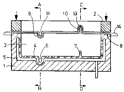
Figure l shows a section through a vacuum mold with
tenter,
Figure 2 shows a top view of the working side of the
tenter,
Figure 3 shows a top view of the lower half of the
mold without tenter,

,? ~ J ~,,
Figure 4 shows a section through line A-B in
Figure 1,
Figure 5 shows a section through line C-D in
Figure 1 and
5 Figure 6 shows the arrangement of a contouring of
the rim in one insert and the
arrangement of the associated contouring
of the tenter in one inser~.
DESCRIPTION OF THE INVENTION
The above object is solved in that the cover
material is at least approximately iitted to the
contourings of the mold cavity in the region of the rim
of the cavity and the tenter (or stretching frame).
By this means, the contourings are already
15 roughly preformed before the cover material slides into
the mold cavity. The creases or bulges formed in the
section of cover material by the corresponding
contourings of the rim and tenter are continued in the
section of cover material located above the mold cavity.
20 These deformations are for the most part preserved
during drawing in and are subjected to the appropriate
fine deformation during application to the contourings
of the mold cavity. Besides the avoidance of undesired
creases and undesired hollow regions in the finished
25 cushion, the drawing-in process is also accelerated.
The lower half of the mold comprises a mold
cavity with pronounced longitudinal contourings tridges
and/or grooves). The cavity is surrounded by a rim, and
a tenter ~or stretching frame) is assigned to the rim.
The novelty consists in that (i) contourings
(which are appropriate to and run in the direction of
the contourings of the mold cavity) are provided on the
rim or in the rim and (ii) the tenter has negative
contourings corresponding to the same contourings of the
35 rim. There are no great problems in providing
Mo-3085
Le A 25 415-US/-CA -2-
_

appropriate con~ourings in the rim and in the tenter.
They may be formed in or formed on the rim or tenter.
Of course, a gap for receiving the cover material must
be present between the contourings of the rim and the
5 associated negative contourings of the tenter.
The contourings are preferably provided in
exchangeable insert pieces. This is particularly
advantageous if different sections of cover material of
varying thickness must be processed. In this case, the
lO gap formed by the contourings may be appropriately
dimensioned by the exchange of such inserts.
According to a further special embodiment the
contourings broaden outwards and flatten out in the
process. By this means the deformation of the section
l5 of cover material is facilitated during drawing-in.
A further, especially advantageous embodiment
is characterized in that the gap formed between ~he
contourings of the rim and of the tenter tapers towards
the mold cavity. By this measure, the drawing-in
20 process is optlmized by a better guiding of the section
of cover material.
The new vacuum mold is represented purely
schematically in the drawing.
In Figures l to 5 the vacuum molded consists of
25 a lower half l of the mold, to which a tenter 2 and an
upper half of the mold (not represented) are associated.
A mold cavity 3 is arranged in the half l of the mold,
which cavity is connected by channels 4 to a vacuum
chamber 5, which is connected to a vacuum pump (not
30 represented). Contourings 6, 7 are arranged on the base
of the mold cavity 3. Contour 6 is in the shape of a
groove while contour 7 is in the shape of a ridge.
These contourings 6, 7 are continued at the rim 8
encircling the mold cavity 3 as contourings 9 (groove)
35 and lO (ridge), and at the tenter 2 as corresponding
Mo-3085
Le A 25 415-US/-CA 3
. _ _

negative contourings 11 and 12. These contourings 9,
10, 11, 12 flatten outwards, and the gap 13 formed
between them increases outwards. A section 14 of cover
material is represented in its stretched state.
Mold half 21 and tenter 22 are represented in
section in Figure 6. The contouring 23 of the rim 24 is
arranged in an insert 27 exchangeably attached with
screws 26 in a recess 25 of the rim 24. A recess 28, in
which an insert 29 is exchangeably attached by means of
10 screws 30, which insert comprises the contouring 31, is
arranged in the tenter 22 in identical fashion.
Although the invention has been described in
detail in the foregoing for the purpose of illustration,
it is to be understood that such detail is solely for
15 that purpose and that variations can be made therein by
those skilled in the art without departing from the
spirit and scope of the invention except as it may be
limited by the claims.
Mo-3085
Le A 25 415-US/-CA 4

Representative Drawing
A single figure which represents the drawing illustrating the invention.
Administrative Status

2024-08-01:As part of the Next Generation Patents (NGP) transition, the Canadian Patents Database (CPD) now contains a more detailed Event History, which replicates the Event Log of our new back-office solution.

Please note that "Inactive:" events refers to events no longer in use in our new back-office solution.

For a clearer understanding of the status of the application/patent presented on this page, the site Disclaimer , as well as the definitions for Patent , Event History , Maintenance Fee  and Payment History  should be consulted.

Event History

Description Date
Inactive: IPC from MCD 2006-03-11
Inactive: Adhoc Request Documented 1995-07-21
Time Limit for Reversal Expired 1995-01-21
Letter Sent 1994-07-21
Grant by Issuance 1992-07-21

Abandonment History

There is no abandonment history.

Owners on Record

Note: Records showing the ownership history in alphabetical order.

Current Owners on Record
FRITSCHE-MOLLMANN GMBH & CO. KG
BAYER AKTIENGESELLSCHAFT
Past Owners on Record
GUNTER MOLLMANN
VOLKER ONNENBERG
Past Owners that do not appear in the "Owners on Record" listing will appear in other documentation within the application.
Documents

To view selected files, please enter reCAPTCHA code :


To view images, click a link in the Document Description column. To download the documents, select one or more checkboxes in the first column and then click the "Download Selected in PDF format (Zip Archive)" or the "Download Selected as Single PDF" button.

List of published and non-published patent-specific documents on the CPD .

If you have any difficulty accessing content, you can call the Client Service Centre at 1-866-997-1936 or send them an e-mail at CIPO Client Service Centre.


Document
Description 
Date
(yyyy-mm-dd) 
Number of pages   Size of Image (KB) 
Cover Page 1993-11-04 1 15
Abstract 1993-11-04 1 16
Claims 1993-11-04 1 31
Drawings 1993-11-04 2 36
Descriptions 1993-11-04 4 133
Representative drawing 2001-07-24 1 12