Note: Descriptions are shown in the official language in which they were submitted.
13C~5~24
WIRE INCRUSTED WIT~ ABR~SI~ GE3,AIN
A~ID METHOD FOR PRODUCING TEIE SAME
BACKGROUND OF THE INYENTION
The present invention relates to a metallic wire
for cutting, grinding or chamfering processing of hard
materials and the like and, in particular, to a metallic
wire for cutting and grinding processing having abrasive
grain powder arranged and retained uniformly and firmly in
the surface layer and to a method for producing the metallic
wire.
In recent years, it has been studied and carried
out to use a metallic wire for cutting of hard materials
, .
such as ceramics and the like or semiconductor materials
such as silicon, gallium arsenic, and the like and further
for chamfering processing of fine through holes in
workpieces.
As a wire used for the above-mentioned uses, a
wire with high tensile strength, that is, a so-called
saw wire is used. In this case, processing such as cutting
or the like is carried out under the condition that free
abrasive grains are existing between the wire and a material
to be processed and grinding actions are pexformed only by
frictional force, so that a problem that the processing
efficiency is bad is presented.
- 1 - ~ '
13~S~2~
Furt~er, for the cu~ting, ~ere is a so-c,alled
electro-spark machini~g method i~ wh,ich.a high ~olt~ge is
applied between the wire and a m.aterial to ~.e cut to cut
the material by discharge between the both. The method,
however, has a proble~ that the material to be cut is
l.imited only to electroconductive materials.
Recently, a diamond wire produced by coating the
urface of wire with diamond powder by a plating process
h.as been developed and an efficient processing method using
t.he wire and utilizing the grinding force of the diamond
powder on the surface of the wire has begun to be studied.
H'owever~ in the method also, the diamond powder is only
stuck to the wire surface mainly by a Cu or Ni plating layer,
so that it has weak adhesion,to the surface and also the
uniform arrangement.and retention of it over the whole sur-
face of the wire are difficult. Therefore~ such a method
m,ay be reminded that diamond powder is mixed in usual bond
metal powder such as Ni, Cu, or the like and then the mixed
material is sintered and fixed to the whole surface of wire
to produce a diamond wire by applying a usual manufacturing
technology fo~ a diamond grindstone.
Howe~er, even if the abo~e-me~tioned method of
sinterin.g and fixi~g the dia.mond powdex mixed with the ~ond
metal powder to the wh.ole su~face of the wire is a~ idea.l
method certainly, it is impossible ~y any means to produce
such a long and thin wixe by a usual sintering method at
present.
-- 2 --
:1305324
~ the oth,er han.d, double-structure wires such as
wires coa.ted ~ith copper Q~ ~lumi.n.um a~xe P.oW in ge~ex~.l used.
If such an. abrasive gxa.i.n/steel stxuctu~e ~i~e a,s aimed by
t~e inventio~ is take~, as ~ mexe double-structure steel
wire a~d a conventional manufacturing technology for the
double-structure wires is applied to produce the abrasive
grain/steel structure wire, a die for wire drawing is
markedly attacked and abraded by the abrasive grains, for
example, in a wire drawing process, so that it is impossible
practically to apply the conventional wire drawing proces-
sing technology to the production of the above-mentioned
abrasive grain~steel structure wire.
SUMM~RY OF THE INVENTION
In view of the above, an object of the'invention
is to provide an wire incrusted with effective abrasive
grain powder more uniformly and firmly and having an im-
proved cutting and grinding processing function.
Anothex object of the invention is to provide a
method for producing an abrasive grain incrusted wire having
the surface la~er made of more uniformly and firmly arranged
effecti~e apr~,sive g~ain, po~der to i~prove cutting and
grinding processing function.
The wire incrusted ~ith ,a,b~si~e gxa.i~s ,accordi~,g
to the present in~ention is obtai~.ed ~y t~e- followin,g steps~
First, a metallic rod made of a metallic material of the
-- 3 --
13~S324
same kind ~it~.or di~ferent ki~d ~rom ~ metallic pipe 1
made of a desired metallic. ~atexi~ is i~ser~ed i~to the
central par~ of the met~llic pipe 1 With.~ ga.p S foxmed
between the both to obtai~ a constructed metallic body A
having desired dimensions, then the gap S is filled with a
mixture D containing metallic powder 4 and abrasive grains
3 having Mohs hardness of 6 or mDre as the main component, and
a.fter that, end parts of the metallic body A are sealed
hermetically.
Subsequently, hot working such as extrusion
cr rolling, or a heat treatment such as annealing or patent-
ing is applied to the above-mentioned metallic body A
h.aving its ends hermetically sealed and after that, the
. metallic body ~ is subjected to a cold . working
:t.o produce a wire of desired diameter.
After that, the residual metallic pipe 1 positioned
æt the outermost layer of the above-mentioned wire is removed
by polishing, . pickling, and the like and thus
an abrasive grain incrusted ~ire having a mixed layer D'
exposed on the surface of the central metallic rod 2 is
obtained, the mixed layer D' ha~ing the above-mentioned
abrasive grain 3 xetained uniformly and fixmly in the
metallic layer 4' consisti~.g of sintered ~eta.llic powder~
-- 4 --
13053Z4
The fixst ~spect an.d t~e second aspect of the
invention are the thUs o~tain.ed Wi~e itself incxusted with
abrasive grains and a method. fox producin.g the ~ire, respec-
tively. It is à remarkable chaxacteristic of the invention
that abrasive grains mixed with the metallic powder are not
limited to diamond powder and CBN (cubic boron nitride)
powder but ceramics, superhard alloysl glass, and the like
having Mohs hardness of 6 or more can be used as the abrasive
grain, and, in particular, ceramics such as alumina (~Q2
silicon nitride (Si3N4), and the like are also usable.
The Mohs hardness herein is an empirical scale to
determine the hardness of ores by comparison with ten kinds
of ores providing standards. The standard ores in an order
of the softest ore (having a scale of 1) to the hardest one
~having a scale of 10) are talc, g~psum, calcite, fluorite~
apatite, orthoclase, ~ualtz topaz, corundum, and diamond.
Abrasive grains used in the invention have usually hardness
larger than that of orthoclase standard having hardness of 6.
Abrasive grains having.hardness lower than that of ortho-
clase standard are not appropriate in respect of theperformance of obtai~ed Wire incrusted with abrasi~e grains~
Further, the a~o~e-me~tion.ed abra.sive grains ~re
usually mixed with meta.llic powdex an.d t~e ~iXturç i~. a
powdered. state is filled in.to a gap i~ the abo~e-me~tioned
metallic body but it is effecti~e to granulate the above-
13Q532~L
mentioned mixtu~e ~n.d to fill the resulting granules into the
gap for th~ purpose of prevçntiP,~ the meta,~lic powdex a,nd the
a~rasi~e gXa,i~s from ~epa,r~tiaP~ ox segre~ation. caused ~y
difference in gravity bet~een, the both.
A pipe-shaped .''. metal
B may be fitted tightly arou~d the metallic rod 2 inserted
into the central paxt of the metallic pipe 1 with a gap
formed between the metal B and the pipe 1 or a thin metallic
belt C may be wound around the above-mentioned rod to remove
possibilities that, in ~ cold wire drawing process, the
above-mentioned inserted metallic rod 2 is pierced with
abrasive grains and it is notched in its central part.
In the above-mentioned case, for the pipe-shaped
metal or for the wound thin metallic belt, not only the
same metallic component as that of the metallic pipe and
metallic rod but also a metal~ic component different from
~at of t~e above-mentioned pipe and rod can be used.
According to the thus obtained wire incrusted
with abrasive graiPs a,nd to a method for manufacturing the
wire, it is easy to form the metallic pipe and the central
metallic rod separatel~ into ,a,~ appropxiate $ize ~y using
the componen,ts of the same kin.d ox of diffexent kind that
fit the use co~ditions fox the ~Qth.
13~S~2~
As a mixture composed Q~ metallic powder ha~ing
various components and ~rasi~e grain p~de~ ha.~iP.g a Mohs
hardness of 6 or mo~e mixed at a suitable ratio for yarious
use conditions as a main component is filled into a gap
between the metallic pipe and the metallic rod to form a
metallic body and after that, the both ends of the metallic
body are hermetically sealed, it becomes possible to apply
hot working and subsequent cold working
to the metallic body while maintaining the mixing ratio
and the homogenuity of the mixture when the mixture is
prepared. Further, as the outermost layer of the above-
mentioned metallic body is a metallic pipe and a wire draw-
working is brought into contac~ with only the metallic pipe
during a wire drawing process, the wire drawing die is not
brought into contact with the abrasive grain powder, so
that the abrasive grain powder is firmly stuck to the wire.
As the thus obtained wire of desired diameter has
the outermost layer consisting o only the metallic pipe,
if the metallic pipe layer is removed, the mixed layer con-
taining abrasive grains is exposed on the outermost surfaceof the resulting wire. ~ccordingly, the wire incrusted.
with abrasive grains ca.n be produced readily and cheaply.
13~S3Z4
BRIEF PESCRIPTIO~ O~ THE ~RAWINGS
Figs. l~a) a~d l~b) are a pl~n ~iew ~nd a side
sectional ~iew s~owing the st~ucture of a ~etallic body
used in the present invention, xespecti~e~Y;
Fig. 2 is a conceptional view showing a wire
incrusted with abrasi~e grains produced by the method of
the present invention;
Fig. 3(a) is a microphotograph (of 40 magnifications)
showing one example of the surface of
the wire of the present invention;
Fig. 3(b) is a microphotograph (of 40 magnifications)
showing one example of the section of
a wire before being polished and pickling on
the course of production by the method of the present inven-
tion;
Figs. 4(a), and 4(b) are a plan view and a sidesectional view showing a modified example having a pipe-
shaped metal fit tightly around the metallic ro~ repectively; and
Figs. 5(a) and 5(b) are a plan view and a side section~l
view of another modified example having a thin metallic belt
wound around the metallic xod, xespectivelY.
DETAILE _DESCRIPTI OF T~E PREFERREP EMBODIMENTS
The present inYe~tio~ ~ill be descxi~ed i~ moXe
- details wit~ respect to the pxeferred embodiments.
13~5~2q~
Figs. 1~ .nd l(b).a~xe a pla.n ~iew and a, side
section.al yiew, each sho~ing the st~uctuXe of ~ met~llic
body A ha.~i~g a metallic xod 2 inserted in.to the ce~tral
part of a metallic pipe 1 ~d haYing a gap between. the
metallic pipe and the metallic rod fil~ed with a mixture
principally comprising me.tallic powder and abrasive grains.
In Figs. l(a) and l(b), A shows the metallic body,
1, the outermost metallic pipe D and 2, the metallic rod in
t'he central part of metallic pipe. The metallic rod 2 is
inserted into the central part of the metallic pipe 1 with
a gap S formed between the two, and a mixture of abrasive
.grains 3 having a Mohs hardness of 6 or more with metallic
powder 4 is filled in,to the gap S.
As the material of the metallic pipe 1 positioned
at the periphery of the metallic body A and of the metallic
r~d 2 in. the central part of the metallic body A, carbon
steel is used generally but stainless steel, a copper alloy,
or the like may be used according to the use conditions, and
materials of the metallic pipe 1 and the metallic rod 2 may
be different from each othex.
The thickness of,the ~eta.llic pipe 1, the diameter
of the metallic xod 2, and the Width o~ the gap ~etween the
both are each determined ~ppropxiately ~ccording to the di-
ameter of a final wire for use, to the a~exage gra.i~ size of
abrasive grains 3 and to ~ mixing ~atio of the abrasive grain
3 to the metallic powder 4.
_ g _ .
~3C~S~24
Further, as the a~xasi~e gra.in powder 3 having a
Mohs hardness ~f 6 ox more, thexe are specifica~ll~,.i~
additiion to diamond powdex and CP~ powder, ceramins such
as alumina (AQ2O3) and silicon nitride (Si3N4), hard
metal powder, glass powder, and the like, and they are
used in the form of a single compound or of a mixture of
two or more compounds.
As the metallic powder 4 with which the abrasive
grain powder 3 is mixed, Ni powder or Ni base alioy powder
is generally used but, other than those, Cu powder, Cu base
alloy powder, Co powder, Co base alloy powder,.and the like
which are bond metal powder used for manufacturing of general
abrasive grain tools may be used. Both ends of gap S
of the metallic body A after being filled wi~h the mixed
powder D are capped.with an appropriate cover material and
then welded to seal the metallic body A hermetically. After
that, hot working such as extrusion or rolling and then a heat
treatment such as annealing or patenting is applied and
subsequently, cold working is applied to the
metallic body ~ to produce a wire having a desired diameter.
If t~e diffusion of the metallic powder 4 filled
in the gap between the ~etallic pipe 1 a~d the central
metallic xod 2 into the m.etallic pipe 1 ox into the ~etallic
rod 2 during the hot working is undesirable, it is
possible to pre~en~ the diffusion phenomenQn ~ plati~g the
-- 10 --
.. . .. , .... .. _ . . . . . . . . _ _ _ . . . _
~3~53Z4
inner sur~ace of the metallic pipe 1 o~ the outer surf~ce
o~ the metallic ~od 2 With copper or t~e like-in adv-~ce to
form a layer to prevent t~e diffusion.
Also, as shown in Fig. 4 and Fig. 5, a pipe-shaped
metal B may be fitted tightly around the mPtallic rod 2
inserted into the central part of metallic pipe 1 with a gap
formed between the metal B and the pipe 1 or a thin metallic
belt C may be wound around the rod 2. That is effective to
remove possibilities tha~, in a cold working
the above-mentioned inserted metallic rod 2 is pierced with
a~rasive grains and it is notched in its central part.
Further, if, for example, a mixture of diamond
- akrasive grain powder and Ni powder is filled into
the gap, the two types of powder have a tendency
tc segregate and separate due to a difference in gravity
between the both because the specific density of diamond
and Ni is 3.5 g/cm3 and 8.g g/cm3, respectively. ~ wire
p~oduced by use of the above-mentioned mixed powder having
non-uniform composition and containing segregation
shows a marked differçnce in
the density of exposed abrasive grains at di~ferent
locations on the Wire surface, so that there are possibilities
to provide an improper product.
-- 11 --
13~5;~24
To prevent the aboye-mentiQned defect, the m.ixed
powder comp~ising dia.~ond abxasive ~Xains a~.d ~i powd.ex is
granulated to prepare po~de~ comprisin.g sphexical gran.ules,
which is filled into the gap between the above-mentioned
metallic pipe and central metallic rod.
In the process, there are no possibilities that
diamond abrasive grains separate or segregate from Ni powder.
To conduct a granulation-treatment, a binder is
aclded as an additive but if a binder such as an organic
compound is used, joining between particles of powder is
sometimes hindered by the above-mentioned binder when the
above-mentioned metallic body is treated in after processes.
Therefore, it is effective to heat the above-~.entioned metallic
bc~y aftex the granulated pcwder has been filled into the gap and before
er.~ parts of the metallic body A are sealed henmetically to deca~se and
ev~porate the binder and remove a cause for the above-mentioned h~kanoe.
After the cold working, the residual
metallic pipe 1 as the outermost layer of the wire is
removed by polishing, pickling and the like.
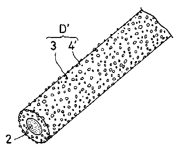
Fig~ 2 shows the thus obtained wire incrusted with
abrasive grains ha~ing a mixed layer D' exposed on the sur-
face of the drawn central metallic xod 2, the m.ixed layer
D' ha~ing the abrasiye grains xetained uniformly and fi~mly
in the metallic layex 4' consistin.g of sintered meta.llic
powder~
- 12 -
13û5324
Fig. 3(a) is a micxogxaph showing on.e e~ample of
the surface ~eta,llic s~XUc~u~e o~ the thus o~ta,i.n.ed.wixe.
Subseque~tl~, speci~ic exa.mples to produce a wixe
incrusted with abrasi~e gxai~.s by the method of this inven-
tion will be described hereinaftex.
Example 1
In a metallic body A shown in Fig. 1, as thematerial, JIS-SS 41 steel material was used for the peri-
pheral metallic pipe 1 and JIS-SK 7 steel material for the
central metallic rod 2. As the size of the metallic body
A" the outermost diameter was 70 mm~, the thickness of the
peripheral metallic pipe was 5 mm, and the width of the gap
S was 8 Imm.
As the abrasive grain, diamond grains were used,
and fine diamond powder having an average particle size of
150 ~m was mixed with mixed powder prepared by mixing 0.5
by weight of carbon with pure nickel powder at a mixing
ratio of 13% by volume of the diamond powder to prepare a
mixture D. After the gap in the metallic body A was fil~ed
with the mixture ~, bot~ ends of the gap part were
and sealed hermeticall~.
Af.ter that, ~he metallic bod.~ A ~as hea~ed at
1000C for 2 hou~s a.n~ the~ ex~xuded ~ an extxusion xato
of 15. Further, a heat tXea.tme~t a~d cold woxking
were repeated to produce a wire of.l.Q ~m~.
13~5;:~Z4
The tensile stren.gth of the wire was 182 kg/mm2. Fig. 3(b)
is a microgra~h showin,g o~e example of ~et~llic structuXe
in the sectio~.of the wire.
The thus obta,ined wire wa,s dipped into a hydro-
chloric acid solution. conoentration of 35% for lS nunutes todissolve and remove the carbon steel material (SS 41) of
the metallic pipe which remained as the outermost layer of
the wire and after that, it was neutralized with an alkali
solution and washed with water.
Fig. 3(a) is a micrograph showing one example of
metallic structural state of the surface of the thus ob-
t~lined wire incrusted with diamond abrasive grains, and it
i:3 realized that fine diamond grains are stuck to and em-
bedded into the peripher~ of the wire uniformly and firmly.
E,~ample 2
,In the metallic body A shown in Fig. 1, as the
material~ JIS-SS 41 steel material and JIS-SUS 304 sta~ess steel
material were used for the peripheral metallic pipe l and
for the central metallic rod 2, respectively. As the size
of metallic bcdy A, the outermost diameter was 70 mm, the
thickness of the peripheral metallic pipe 5 mm and the
width of t~e gap S in the metallic body A 8 mm.
As the abra.si~e grain, CBN grains Wexe used, and.
CBN grains hav.ing an a~erage particle size of 150 ~m Were
mixed with pure nickel powder at a mixing ratio of 13%
- 14 -
~3~5~24
by volume o~ CBN ~rai~s to prepare a mix~ure P. ~fter the
gap part of the meta.llic b~dy A w~s fiIled with the mix-
ture D, both ends o the gap part were sealed
hermetically.
S After that, the metallic body A was heated at
1050C for 2 hours and then extruded at an extrusion ratio
of 15. Further, a heat treatment and cold working
were repeated to produce a wire of 1.0 mm~
The tensile strength of the wire was 183 kg~mm2. The wire
was dipped into a hydro~hloric acid solution of conoentration o~
35~ to dissolve and remove the outermost carbon steel
material (SS 41) of the metallic body A which remaine~
as the outermost layer of the wire an.d after that, it was
neutralized with an alkali solution and washed with water.
The thus obtained wire incrusted with abrasive
grains was used for cutting and grindiny processing of iron
based materials and as a result, extremely good cuttin~
and grinding processing could be performed, whereas, with
the conventional diamond wires produced by a plating method,
the surface diamond grains were abraded intensely owing to
the action of the ixon of the surface of the worked iron
material and processi~g of t~e iro~ m~terial with the wire
was difficult.
- 15 -
13~S~Z4
Example 3
As th,e mate~ia,l of,m~a,llic body A sh.o~ in
Fig. 1, JIS-SS 41 steel m~terial a.n.d.JIS-SK 7 steel ~a~eria.l
were used for the outermost me~allic pipe 1 and for the
central metallic rod 2, respectively. As the sizP of the
metallic body ~, the outermost diameter was 70 mm~, the
thickness of the outermost metallic pipe 7 mm, and the width
of the gap S in the metallic object A 7 mm. Diamond powder
o:E average particle size of 30 ~m was m.ixed with a mixture
prepared by mixing 0.5% by weight of carbon. with pure
n.ickel powder at a mixing ratio of 15% by volume of diamond
powder to produce mixed powder D. After the gap S of the
metallic object A was filled with the mixed powder D, both
ends of the gap S were sealed hermetically.
After that, the metallic object A was heated at
11)50C for 2 hours and then extruded at an extrusion ratio
o:E 15. Further, a heat treatment and cold -' working
were repeated to produce a wire of 0.26 mm~. The
tensile strength of the wire was 179 kg/mm2. The wire was
dipped into a hydrochloric ,acid solution of con,oentratio,n o~ 35%
for 5 minutes to dissolYe and remo~e the outexmost carbon
steel matexial (SS 41) of the metallic object A which remained
as the outermost la~er of,the Wi~e ~.~d ,a,ftex th~t, it wa.s
neutralized with an alkali solution. and washed With water..
- 16 -
` ~3(;~S324
The t~us obtained wire incrusted with diamon,d
abrasi~e grains, a,s clea~l~.shQ~n ~om the xesults in Table1
and Table 2 ~escribed la.te~, had st~ong adhesian af diamond
abrasi~e grains 3 to t~e surface of wire, an increased.
cutting speed and a markedly long life as compared with
the conventional diamond wires ha~ing the same diameter and
diamond powder stuck to the surface by a plating method.
One example of results of the above-mentioned
comparative experiments is shown in Table 1 and Table 2.
Table
_
Material of work: Pre-sintered body of
WC-12~ Co alloy
Size of work: 35 mm diameter
Wire incrusted with Diamond wire
diamond by method by conventional
Test items of inventionplating method
Lineat velocitY
(m/sec~ 8 4
Load (kg)
Cutting` time 45 440
(sec)
Cutting speed .1296 131
(mm2 /min)
Finishing condition Good Good
Total time of life
(hr) about 210 about 30
.
- 17 -
... . . . . . _ _ . . . ... ... . . . . . _ . . . .. _ . _
13(~5;324
TabI~ 2
Material Of work: Si sin~le cr~stal
Size of work: 50 mm diameter
.
Wire incrusted with Diamond wire
diamond by method by conventional
Test itemsof invention plating method
Linear velocity 150 150
(m!sec)
J.oad lkg) 4 4
_
~utting time 12 4 53
(min ) ,
Cutting speed 158 3 37.0
(mm2 ~min)
i~inishing condition Good Good
- - about 40 about 8.5
_ ( r
E:~ample 4
As the material of metallic body A
s}lown in Fig. 1, a carbon steel pipe (JIS-STK 30 )
and a piano wire ~JIS-SWRS 72~) were used
for the peripheral metallic pipe 1 and for the central
metallic rod 2, respectively.
As the size of metallic body A,
the outermost diameter was 20 mm, the thickness of the
metallic pipe 2 mm and the diameter of the metallic rod
13 mm.
As the ~brasive grain, fine diamopd powder having
an average particle size of 30 ~m was used. The dlamond
powder was mixed with Ni powder at a
mixing ratio of 15% by volume of diamond powder to prepare
- 18 -
~3(~S32~
a mixture and furthe~, to the mixture, 0.5% by weight of
camphor as a ~inde~ Was added to p~epare ~ixed powder.
After that, the mixed powder: was gxanulated ~ a ~et spray
method to prepare gxanules, which wexe then held in a
nitrogen atmosphere at 300C for 1 hour to sublime camphor.
Thus, a mixture D comprising the granules was produced.
After ~he mixture D was filled into the gap of the
metallic body A, both ends of the metallic body A were
.sealed hermetically
After that, ~he-metallic body A was not extruded
bQt a heat treatment and cold working were
repeated to produce a wire of 0.26 mm~. The tensile
! strength of the wire was 180 kgtmm2.
By the same way as in Example 3, the outermost
layer 1 of the metallic bod~ A was dissolved and removed>
a:nd after that, the resulting wire was neutralized with an
a~ueous alkali solution and washed with water.
The wire was used for cutting processing and as a
rcsult, good cutting performance comparable to that in
Example 3 was obtain.ed.
Example 5
As the ~aterial of ~etallic body A
shown in Fig. ~, a cargon steel mate~ial ~IS-SS-41~ ~
and a carbon steel material (~IS-S~
7) were used for the peripheral metallic pipe 1 and for the
central metallic rod 2, respectively.
-- 19 -- .
~3~5324
.
As the size o~ the met~llic bod~ A,
the outermost diamet~r was 70 m~, th,e tkickness of,the
metallic pipe 5 mm, and ~e width o~ the ga.p S 6 mm.
A pure nickel tube B having an inner diameter of
48 mm and a wall thickness of 2 mm was inserted into the
gap S to fit it tightly around the metallic rod 2. Diamond
powder having an average particle size of 120 m was mixed
with a mixture prepared by mixing 0.5% by weight of carbon
with pure nickel powder at a mixing ratio of 13~ by volume
of diamond powder to prepare mixed powder D. After the
gap S' between the above-mentioned Ni tube B and the metal-
lic pipe 1 in the metallic body A was filled with the mixed
powder D, both en,ds of the gap S in, the metallic object A
were sealed hermeticallyO
After that, the metallic body A was heated at
1050C for 2 hours~ and then extruded at an extrusion ratio
of 15. Further, a heat treatment and cold working
were repeated to produce a wire of 1.0 mm~. The
tensile strength of the wire was 168 kg/mm2.
The structure of the wire was observed on a micro-
photograph and as a result, it was f'ound that diamond
particles were separated from t~e central metal rod ~y the
pipe-shaped nickel metal and t~e cent~al metal rod was n,ot
pierced with dia.mon.d particles and was not not~hed.
, - 20 -
13~5~Z4
Next, the wire was dipped into a hydrochloric acid
solution of conoentration of 35% for 15 minutes to dissol~e a.n.d
.remove the outermost metallic pipe of caxbon steel (SS 41)
of the metallic body A which remained as the outermost
s layer of the wire. After that, the resulting wire was
neutralized with an a~ueous alkali solution and washed
orith water.
The thus obtained wire incrusted with diamond
z.brasive grains was a wire of long life which had the outer
E~eripheral part stuck uniformly with diamond particles and
t.he inside part not pierced with diamond particles into the
.center part and not notched.
Example 6
As the material of metallic body A
shown in Fig. 5, a carbon steel pipe (JIS-STK 30)
and a piano wire (JIS-SWRS 72B) were used
for the peripheral metallic pipe 1 and for the central
metallic rod 2, respectively.
As the size of the metallic body A,
the outermost diameter was 20 mm, the thickness of the
metallic pipe 2 mm, and the dia.meter of.the metallic rQ~
12 mm.
~ thin belt C of pure nickel of 0.1 mm thick Was
woun.d densely a.round the metallic rod 2 to form a nickel
belt layer of thickness of 0.5 mm on. the ~od ~. After a
- 21 -
13CP53~
gap S' betw,een the ~ickel belt and the meta,llic pipe 1 ~as
filled with m.ixed powde~ ~ p~ep~ed hy mixi~ CB~ ~bx~sive
grains 3 ha~in.g an a.yexage grain size of,30~ m wit~ pure
nickel metal powder at a m.ixing Xatio of 13% by volume of
CBN abrasive gxains 3, both ends of the gap S were capped
and after that, were sealed hermetically.
After that, a heat treatment comprising heating
to 950C and subsequently being allowed to cool by air
a~.d cold working were applied
to the metallic body A seven times repeatedly to produce a
w;re of diameter of 0.26 mmD ~he tensile strength of the
wi.re was 171 kg/mm2. The wire was dipped into a hydrochloric
ac:id solution of o~ncentration of 35% for 5 minutes to dissolve
and remove the outermost carbon steel (STK 30) material of
the metallic body A which remained as the outermost layer
of. the wire~ After that, the resulting wire was neutralized
with an alkali solution and washed with water.
As shown clearly by the results in Table 3,
th.e . thus obtained wire incrusted with CB~
abrasive grains was a wire of markedly long life which had
no possibilities tha~ thç centxal ~etallic rod was pierced
with CBN abrasi~e grains and ~as notched easily and the
wire fractuxed easil~, as compaxed With, a Wixe incrusted with
CNB abrasi~e grai~s of th,e same diametex pxoduced b~ the
con~ention,al wire drawing method using none o~ a pipe-,
shaped metallic body and a thin metallic belt.
~3~5;~2~
-- . . . .
Material of work: Pre-sintered body of
WC-12~ Co alloy
Size of work- 50 ~m diameter' '
Wire incrusted Wire incrusted with
~ith CBN by CB~ by conventional
method of wire drawing method
Test items in~ention
Linear velocity 8
(m/sec)
Load (kg)
._
Cutting time 1 6 1~7
', (min)
Cutting speedJ 1217 1159
Finishing condition Good Good
Total time of life about 215 about 126
(hr)
E;xample 7
As the material~of metallic body A
shown in Fig. 1, a JIS-SS 41 steel material and a JIS-SUS
304 sta~ess steel material were used for the peripheral met~llic pipe
1 and for the central metallic rod 2, respectively. As the
size of the metallic body _, the outermost
cliameter was 70 mm, the thickness of the peripheral metal-
lic pipe 5 mm, and the width of gap S 8 mm. A~ter the gap
S of the metallic body A was filled with mixed powder ~
prepared by mix,ing alumina (A 23j powdex 3 ~aving an a~erage
particle size of 150~ m with pu~e ~i po~der at~a mixing rati~
of 13% by Yolume of alumina, both e~ds of the gap S of the
metallic body A were sealed hermetically.
- 23 -
~3U5324
After t~at, the metallic body A was heated at
105~C ~or 2 hours a~d then extruded at an extrusion ratio
of 15. Further, a heat treatmen.t and cold working
were repeated to produce a wire of 1.0 mm~. The
tensile strength of the wire was 183 kg/mm2. The wire was
dipped into a hydroc~loric acid solution of conoentration of 35%
to dissolve and remove the outermost carbon steel (SS 41)
material o the metallic body A which remained as the
outermost layer of the wire. After that, the resultinq
wire was neutralized with an alkali solution and washed
with water.
When the thu.s obtained wire incrusted with abrasive
grains was used for cutting and grinding processing of iron-
containing materials, it could show very good cutting and
g.rinding performance, whereas diamond powder on the surface
of diamond wire produced by the conventional plating method
W.lS abraded intensely owing to the iron on the surface of
the worked iron material and processing of the material
w.ith the diamond wire was difficult.
Example 8
~ s the material of metallic body A
shown in Fig. 1, a carbon steel pipe ~JIS-STK 30)
and a piano Wire ~JI5-SWRS 72B) ~ere used fox the
peripheral metallic pipe 1 and fox the central metallic rod
2, respectively.
- 24 -
13G53Z4
As the size of the ~etallic body _,
the outexmQst di,a,metex Was 2~ mm, tbe thickn.ess ~f the
metallic pipe 2 mm, ~n.d the di.a.~etex of th,e meta.llic xod
13 mm. Aftex the gap S betwee~ the metallic pipe 1 and the
metallic rod 2 was filed with mixed powder D prepared by
mixing silicon nitride ~Si3N4) powder 3 as abrasive parti-
cles having an average particle size of 30 ym with copper
powder at a mixing ratio of 15% by volume of silicon nitride
powder, both ends of the gap S of the metallic body A were
s,_aled hermetically.
Aftex that, a heat treatment comprising heating
to 900C and subsequently being allowed to cool in air
a:nd cold working were applied ~o
the metallic body A seven times repeatedly to produce a
wire of diameter of 0.26 mm. The tensile strength of the
wire was 154 kg/mm2. The wire was dipped into a hydro-
chloric acid solution of concentration of 35~ for 5 minutes to
dissolve and remove the outermost carbon steel (STK 30)
material of the metallic body A which remained as the outer-
most layer of the wixe. After that, the resulting wire wasneutralized with an alkali solutio~. an.d washed with water.
The thus ohtain.ed Wixe i~cxusted with abrasive
grains ~as used, fox cutti~ of Si si~le cx~stal ~nd as a
resuIt, yex~ good cuttin.g processin~ could ~e per~o~med.
. - 25 -
13~5~24
As described above, according to the invention, a
metallic body fo~med easily Lnto suitable d~sions
and by suitable materials for use conditions is used, and
after t~e gap within t~e metallic body is filled with mixed
powder prepared by mixing metallic powder of d sired com-
ponents and mixe~ ratio with abrasive grains having Mohs
hardness of 6 or more at a desired mixing ratio, both ends
o:E the gap are welded and sealed hermetically. As the ,
outermost part of the metallic body is only a metal of
metallic pipe, even if ~he conventional double structure
w,ire producing technology is applied to the metallic body
w.ithout any change, there are no possibilities that the
abrasive grains directly attack a die for wire drawing,
so that the metallic bod~ can be subjected to wire dra~ng ,prccessin~
easily up to a desired wire diameter as in the production
process for the conventional double structure steel wire.
Further, also in the final process to expose a
mixed layer containing abrasive grain powder having Mohs
hardness of 6 or more as the outermost layer of wire, a
metal remained on the sur~ace of the wire can be removed
readily by applying a usual polishing, , pickling~
or the like.
~ s a he~t tre~tme~t i~ a,~, extensi~e ~eanin,g in-
cluding direct hot working a.nd cold working
are applied to the metallic ~ody having the mixed
- 26 -
13~5324
powder filled into the gap hermetically, the above-
mention.ed a,~rasive grai~ powder i~ the ~ixed layex formed
of sintered metallic powder in the mixed powder can
be arranged and retained uniformly and firmly maintaininq
its mixing ratio at the time of filling
unchangedO Thus, a wire incrusted with abrasive grains
suitable for cutting and grinding processing can be pro-
duced readilyf which can have an increased cutting speed
and a markedly extended wire life and has very excellent
cutting or chamfering processing performance as compared
with the conventional diamond wire having diamond
,Fower only stuck to its surface by a plating method.
Further, the wire of the present invention has
also markedly large retaining power for abrasive grains
w.hen the wire is bended as compared with the wire produced
by the plating method.
As the wire incrusted with abrasive grains pro-
duced by the method of the invention has abrasive grains
firmly embedded into the surface of wire, it, as a wire for
precise cutting, is most suitable for cutting of a brittle
material or of a material hard to be applied by a cuttin.
method using a li~uid such as water or an oil.
- 27 -