Note: Descriptions are shown in the official language in which they were submitted.
L3~
K 9447
APPARATUS AND PROCESS FOR SOLIDS-FLUID SEPARATION
m e invention relates to an apparatus and a process for
solids-fluid separation and to products obtained ~y such a process.
It is kncwn to separate solids from gases by imparting a
rotating movem~ent to a solids-gas mixture which is entered
substantially horizontally and tangentially in a vertical
cylindrical body (e.g. a cyclone) from which gas is discharged at
the top and solids are discharged from the bottcm.
In order to attain substantially ccmplete removal of small
solid particles (e.g. catalyst fines) from gases, as desired in
e.g. catalytic cracking processes, a number of cyclones is usually
required even when the bulk of the solids has already been removed
in a preceding separation stage (e.g. by means of deflection plates
or cyclones). As a consequence of the horizontal feed inlet means
extending tangentially from each cyclone body, a housing (e.g. a
reactor vessel) having substantial dimensio~s would be needed to
accommodate a number of cyclones.
Alternatively, such cyclones could be placed outside a reactor
vessel, thus requiring complex bracing in order to withstand the
prevailing pressure differentials at relatively high operating
temperatures (e.g. 400-600 C inside the cyclones).
Moreover, in both cases undesired coke- and hydrogen formation
(i.e. after-cracking) may take place in the various dead spaces at
said high temperatures during the substantial residence time in
such a large apparatus of e.g. hydrocarbon-containing catalyst
particles which are being separated from heavy hydrocarbon vapours.
It is further known to use cylindrical cyclones with axial
; ~ dcwnward entry for solids-gas separation. In conventional multiple
cyclone designs a solids-containing feed stream enters the cyclone
assembly horizontally or under a slight angle (e.g. less than 45
degrees) with a horizontal plane from one side which w~uId require
additional space in case such an assembly is arranged inside a
reactor vessel, as discussed hereinabove for cyclones with
: : :
~ ,
:
,
.
~5~36
-2- 632~3-2707
tangential feed erltry. Moreover, such an arrangement would lead
to a pressure difference between the cyclones near the feed inlet
side and the downstream cyclones, which would cause unequal
distribution of solids-containing fluid over ~he var.ious cyclones.
It has now heen found that the aforementioned
disadvantages which are inherent to the various types of cyclones
can be overcome by particularly arranging tubular eleMents and
inlet- and outlet means in a housing, resulting in a very compact
apparatus for a given solids-fluid separation capacity.
Thus, according to one aspect, the invention provides an
apparatus suitable for solids-fluid separation which comprises a
plurality of substantially vertical tubular elements in a housing,
inlet means arranged in the bottom of the housing and
communicating with the space between the tubular elements and the
housing, a plurality of tubular fluid outlet means of which the
lower sections are arranged substantially co-axially within the
upper sections of said tubular elements defining annular spaces
uherein swirl imparting means are arranged and of which fluid
outlet means the upper sections cooperate with opening(s) in the
upper section of the housing, and solids outlet means
aommunicating with the lower sections of the tubular elements and
with opening(s) in the bottom of the housing.
According to another aspect, the invention provides a
process for separating solid particles from fluid in a housing,
: which process comprises passing a mixture of solid particles and
fluid upwardly into a space between tubular elements in the
housing and subsequently downwardly into annular spaces provided
:
~ : .
~3~5~3 Eii
-2a- 63~93-2707
with swirl imparting means, which annular spaces are defined
between the upper sections of the tubular elements and the lower
sections of tubular fluid outlet; means arranged subs-tantially co-
axially wi~hin said upper sections, imparting a helical movement
to the solids-fluid mixture in the tubular elements -to separate
solids from fluid, removing solids through the lower sections of
the tubular elements and removing ~luid upwardly through the upper
sections of the tubular fluid outlet means.
The apparatus according to the invention can be employed
in processes wherein solids have to be separated from fluids (in
particular gases at elevated temperatures and pressures) such as
catalytic cracking, shale conversion processes and coal- or heavy
oil gasification.
An advantage of the apparatus according to the invention
is the relatively short residence time of the solids and fluids to
be separated, which is o~ particular importance when the apparatus
is applied in a fluid catalytic cracking process for separation of
catalyst (~ines) from hydrocarbon vapours; as a consequence of
short residence times after-cracking of hydrocarbons (and thus
carbon-formation on the catalyst particles) will be reduced,
resulting ln better product yields and less catalyst deactivation.
3~
Moreover, the spread in residence times will be relatively narrow,
which leads to the prcduction of less undesired products and a
longer catalyst life, in comparison with the use of separation
apparatuses in which the residence time .spread is relatively wide.
Furthermore, the apparatus according to the present invention
is very efficient in separating relatively small solid particles
from gases in which said particles are present in relatively small
amounts due to the symnetrical flow pattern in the apparatus which
results in substantially equal loading of each tubular element.
Therefore, the amount of solids carry-over into the separated gases
will be very small, which makes it possible to eliminate recycle of
slurry oil (e.g. catalyst fines in liquid hydrocarbons) recycle in
a fluid catalytic cracking operation from a downstream hydrocarbon
fractionator to the cracking reactor, thus again improving product
yields.
Preferably, the inlet means (through which a mixture of solids
and fluid enters the apparatus) is (are) centrally located in the
bottom of the housing below the tubular elements, in order to
ensure optimal distribution of the upwardly flowing solids-fluid
mixture over all tubular elements in which, to a large extent, the
actual separation takes place.
A suitable number of tubular elements and separation means
belonging thereto may lie between 3 and 80, especially between 5
and 20, more especially between 6 and 12. The tubular elements are
preferably situated in one or ~ore (concentric) circles.
Various embodiments of the apparatus according to the
invention are described hereinafter, using Figures 1-4 in which
reference numerals relating to corresponding parts are ~he same.
In Figure 1 a longitudinal section of a fully enclosed
individual separating apparatus is shown.
Figure 2 represents a longitudinal section of an integrated
apparatus of which the upper separating means is identical to that
dQpicted Ln ~ig~re 1.
,' , .;
,
~3~5~
In Figures 3 and 4 cross sections are shcwn at AA' and ss',
respectively, of the apparatus depicted in Figure 2.
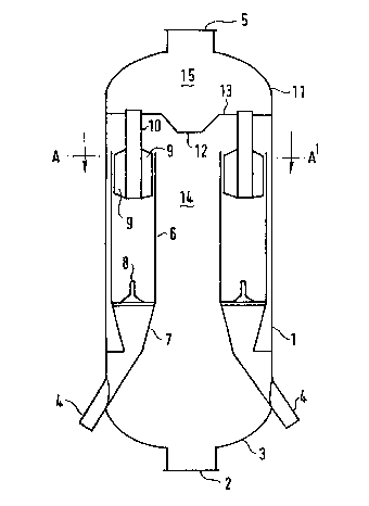
me apparatus depicted in Fig~re 1 comprises a housing (1
provided with an inlet ~2) for an upwardly flcwing mixt~lre of
solids and fluid in its bottom section (3), a plurality of separate
solids outlets ~4) and a combined fluid outlet (5). A number (eight
according to Fig. 3) of substantially vertical tubular elements (6)
are symmetrically arranged in the housing, preferably in such a
manner that they can be easily rem~ved from said housing through an
opening (2 or 5); the lcwer sections (7) of the tubular elements
(6) are suitably downwardly converging. Preferably, vortex
stabilizer means (8) are arranged in the lower sections of the
tubular elements (6) in which, during operation, the mixture of
solids and fluid is subjected to a helical movement. Swirl
imparting means (9) (suitably outwardly curved swirl vanes) are
located in the upper sections of said tubular elements, and are
preferably attached to tubular fluid outlet means (10) which are
arranged substantially co-axially within said upper sections.
Plternatively, inwardly extending swirl imparting means can be
attached to the upper sections of tubular elements (6).
Preferably, only a small number (e.g. 1, 2 or 3) of tubular
elements (6) cooperate with a common solids outlet (4), in order to
avoid fluid and/or solids surging effects ("cross-talk") between
different tubular elements.
me length:diameter ratio of the tubular elements ~6) is
suitably from 1-10, and preferably from 2-5. me ratio of the
diameters of the tubular elements (6) and the tubular fluid outlet
means (10) is suitably frcm 1.5-4, and preferably from 2-3.
me upper section (llj of the housing (1) is preferably
provided with a central downwardly extending fluid deflection means
(12); suitably an inverted truncated cone) arranged in wall (13)
separating the space (14) between the tubular elements (6) frGm
fluid collecting space (15). The presence of fluid deflection means
cen substantially reduce erocion problemr which might otherwiRe
.
.,
. ~`
:.
-
" ' ' ' :
~L3~5;~;~1E;
arise due t.o impingement of solids with a relatively high velocity
on wall (13) when the upward flow of the sollds-fluid feed muxture
is reversed before said mlxture enters the annular spaces between
the tubular elements ~6) and the tubular fluid outlet means (10).
Moreover, the presence of fluid deflection means (12) will in se
cases lead to a reduced pressure drop during operation of the
apparatus.
me apparatus according to the present invention advantageous-
ly further comprises lower pre-separation means (as depicted in
Figure 2 and Figure 4) suitable for the separation of larger (e.g.
catalyst) particles from fluids. This enbodl~ent is particularly
preferred for application in a fluid catalytic cracking process.
The lower separation means ccmprises a domed upper section (16),
upwardly directed feed inlet means (17) cooperating substantially
tangentially with said domed upper section, a central section (18)
provided with outlet means (l9) in ccmmunication with the space
(14) between the tubular elements (6) and the housing, and a solids
outlet opening ~20) in the lcwer section (21) of the separation
means.
Preferably, the domed upper section (16), the central section
(18) and the lower section (21) together form a substantially
spherical body having two vertically flattened sides to provide
spaces (22) between the central section (18) and the housing (l),
through which spaces (22) space (14) is in communication with
(preferably tubular) outlet means (19). In such a substantially
spherical body an optimal flcw pattern of the solids and fluid
streams will be attained which results in high solids separation
efficiency, a relatively short solids residence time (in order to
avoid undesired reactions) and a low pressure drop in the
apparatus.
Suitably, the lcwer section (21) comprises at least one fluid
ventilation opening (23) which is in ccmmunication with spaoe (24)
wherein during operation relatively large solid particles separated
from fluid in the lower separation means are collected together
-- 6 --
with relatively small particles ~fines) flowing through solids
outlets (4) into said space (24). A more detailed description of
this separation apparatus is given in European patent application
No. 86201003.
When the apparatus depicted in Figures 2-4 is employed in a
fluid catalytic cracking process, feed inlet means (17) suitably
form the upper part of a fluid catalytic cracking riser reactor
(25), whereas in space (24) optionally stripping of hydrocarbons
from cracking catalyst particles may be carried out by means of
steam or other stripping gases which are suitably introduoe d
through gas feed means (not shown) into one or more lower sections
of the housing (1). Through fluid ventilation opening (23) vapours
evolving from (pre-) stripped catalyst particles can flow into the
domed separation means.
Hcwever, the (pre-)stripper vapours can also be kept separate
from the vapours originating from the riser reactor, if desired, by
providing a separate vapour outlet for the tpre-)stripper vapours
in an appar~tus without said opening.
me integrated apparatus according to the invention comprises
one or more, preferably substantially horizontal, outlet means (19)
for fluid containing some (catalyst) fines, from which the larger
particles have been separated. Suitably, the outlet means (19)
forms a tube extending through central section (18) and ccmprising
at least one opening (26) preferably located at the lower central
part of the tube, in order to avoid entrainment of catalyst
particles by hydrocarbon vapours during start-up of the catalytic
cracking process when the velocity of the catalyst particles in the
dome is relatively lcw~
During normal operation of the apparatus according to the
invention the (catalyst) particles follow a flcw path in a
substantially vertical plane along the inner wall of domed section
116) and leave section (18) through solids outlet opening (20). In
order to avoid a fIow of solids together with fluid directly from
feed inlet means (17) via lower section (21) to solids outlet
36
opening (20), the latter opening is suitably provided with a shim
(27) which is preferably inclined at an angle from 15 to 45 degrees
with respect to a vertical plane for optimal solids deflection (see
in particular Figure 2).
The ratio of the maximum internal widths of the dome and the
feed inlet means (17) is suitably from 1.5-6, and preferably from
2-4.
The invention further relates to a process for separating
solid particles from fluid, in particular for separating fluid
cracking catalyst particles from gaseous hydrocarbon conversion
products which comprises passing a mixture of solid particles and
fluid upwardly into a space between tubular elements and subsequent-
ly downwardly into annular spaces provided with swirl imparting
means, which annular spaces are defined between the upper sections
of the tubular elements and the lower sections of tubular fluid
outlet means arranged substantially co-axially within said upper
sections, imparting a helical movement to the solids-fluid mixture
te.g. catalyst fines-containing gases) in the tubular elements to
separate solids from fluid, removing solids through the lower
sections of the tubular elements and removing fluid upwardly
through the upper sections of the tubular fluid outlet means.
Preferably, a mixture of solid cracking catalyst particles and
hydrocarbon-containing gases emanating from a fluid catalytic
cracking zone is pre-sepæated by passing said mlxture upwardly and
tangentially into a substantially spherical pre-sepaxation zone,
wherein the mixture is subjected to a rotating move~ent in a
substantially vertical plane, rem~ving catalyst particles through
an opening in the lcwer section of the pre-separation zone and
passing catalyst fines-containing gases from the central section of
the pre-separation zone upwæ dly through the space between the
tubular elements of the next separation zone.
Apart from gaseous hydrccarbon conversion products, other
gases such as flue gases or gases obtained in shale conversion
processes and coal- or heavy oil gasification process c~n also be
~5~
separated from solid particles in the above-described manner.
Preferably, catalyst particles and/or -fines which have b~en
separated by means of said process are passed to at least one
stripping zone which is in gaseous oommunication with the first
and/or second separation zone, and contacted in the stripping
zone(s) with a stripping gas (e.g. steam).
Moreover, the invention relates to hydrocarbo~ conversion
products separated by a process as described hereinbefore.
m e invention will be further elucidated by means of the
following Example.
EX~?LE
A feed stream of hydrocarbon vapours and cracking catalyst
particles in a weight ratio of 40 enters feed inlet (2) of a
separation apparatus as depicted in Figure 1 at a temperature of
520 C, a pressure of 2 bar gauge and a vapour velocity of 6 mls.
Catalyst particles are removed through solids outlets (4) with a
separation efficiency of re than 95% on a weight basis.
- -