Language selection

Search

Patent 1305460 Summary

Third-party information liability

Some of the information on this Web page has been provided by external sources. The Government of Canada is not responsible for the accuracy, reliability or currency of the information supplied by external sources. Users wishing to rely upon this information should consult directly with the source of the information. Content provided by external sources is not subject to official languages, privacy and accessibility requirements.

Claims and Abstract availability

Any discrepancies in the text and image of the Claims and Abstract are due to differing posting times. Text of the Claims and Abstract are posted:

  • At the time the application is open to public inspection;
  • At the time of issue of the patent (grant).
(12) Patent: (11) CA 1305460
(21) Application Number: 1305460
(54) English Title: COMBINATION BACK-UP LIGHT AND SOUND EMITTING DEVICE FOR AUTOMATIVE VEHICLE
(54) French Title: FEUX DE RECUL ET DISPOSITIF SONORE POUR VEHICULE AUTOMOBILE
Status: Expired and beyond the Period of Reversal
Bibliographic Data
(51) International Patent Classification (IPC):
  • B60Q 01/44 (2006.01)
  • B60Q 01/22 (2006.01)
  • B60Q 05/00 (2006.01)
  • F21V 19/00 (2006.01)
(72) Inventors :
  • GOTTLIEB, MARK (United States of America)
(73) Owners :
  • DESIGN TECH INTERNATIONAL, INC.
(71) Applicants :
  • DESIGN TECH INTERNATIONAL, INC. (United States of America)
(74) Agent: LAVERY, DE BILLY, LLP
(74) Associate agent:
(45) Issued: 1992-07-21
(22) Filed Date: 1989-07-24
Availability of licence: N/A
Dedicated to the Public: N/A
(25) Language of filing: English

Patent Cooperation Treaty (PCT): No

(30) Application Priority Data:
Application No. Country/Territory Date
222,730 (United States of America) 1988-07-22

Abstracts

English Abstract


-11-
ABSTRACT OF THE DISCLOSURE
A combination back-up light and sound emitting
device for use with an automobile includes a housing
having a base at one end and a socket at the other
end. A light bulb is mounted in the socket of the
housing and a sound emitting device is also mounted in
the housing. Bayonet type connectors are formed on the
base of the housing and are electrically connected to
the light bulb and sound emitting device. The bayonet
type connectors are used for mechanically connecting
the housing to the back-up light socket of a vehicle
tail light assembly, so that installation of the
combination back-up light and sound emitting device can
be accomplished simply by inserting the base into the
back-up light socket and turning so as to secure the
bayonet type connection.


Claims

Note: Claims are shown in the official language in which they were submitted.

The embodiments of the invention in which an
exclusive property or privilege is claimed are defined as
follows:
1. A combination back-up light and sound
emitting device for use with an automotive vehicle,
comprising:
a housing;
means on said housing for mounting a light bulb
thereto;
an electrically actuated sound emitting device
mechanically and electrically connected to said housing:
means for mechanically connecting said housing
to a back-up light socket of a vehicle tail light
assembly; and
means on said housing for electrically
connecting said sound emitting device and a light bulb
mounted in said housing to said means for mechanically
connecting said housing to a back-up light socket of a
vehicle tail light assembly, whereby the mechanical
connection of said combination back-up light and sound
emitting device to a back-up socket of a vehicle also
provides electrical connection for both said sound
emitting device and a light bulb mounted in said housing.
2. The combination back-up light and sound
emitting device for use with an automotive vehicle

according to claim 1 including a light bulb mounted in
said housing.
3. The combination back-up light and sound
emitting device for use with an automotive vehicle
according to claim 1, wherein said means for mounting
comprise a socket having bayonet type connectors.
4. The combination back-up light and sound
emitting device for use with an automotive vehicle
according to claim 1, wherein said means for mechanically
connecting comprise a base having bayonet type
connectors.
5. The combination back-up light and sound
emitting device for use with an automotive vehicle
according to claim 1 wherein said means for electrically
connecting comprise electrically conductive means in said
housing and connected between said sound emitting device,
said means for mounting a light bulb and said means for
mechanically connecting.
6. A combination back-up light and sound
emitting device for use with an automotive vehicle,
comprising:
a housing having a base at one end and a socket
at another end;

a light bulb mounted in said socket of said
housing;
a sound emitting device mounted in said
housing;
bayonet type connectors formed on said base,
said base and bayonet type connectors comprising means
for mechanically connecting said housing to a back-up
light socket of a vehicle tail light assembly; and
means for electrically connecting said bayonet
type connectors to said light bulb and said sound
emitting device.
7. The combination back-up light and sound
emitting device for use with an automotive vehicle
according to claim 6, mounted in a back-up light socket
of a vehicle tail light assembly.

Description

Note: Descriptions are shown in the official language in which they were submitted.


10~6 006 3
40/
TITLE OF THE INVENTION
__
COMBINATION BACK-UP LIGHT AND SOUND EMITTING DEVICE
FOR AUTOMOTIVE VEHICLE
BACKGROUND OF THE INVENTION
Field of the Invention:
The present invention relates to the combination
of a back-up light and sound emitting device for an
automotive vehicle such as a car or truck.
Brief 3escription of the Related Art:
It is conventional for motor vehicles such as
automobiles to have back-up lights which turn on
automatically whenever the vehicle is shifted into
reverse. It has also been known to provide an audible
signal generating device operating in conjunction with
the back-up light. However, such audible signal
generating devices have conventionally been
inconvenient and time consuming to install, s1nce they
must hook into the wiring.
No product is commercially available which
combines an audio alert sound with the back-up light
bulb assembly itself.
For example, in U.S. Patent 1,958,028, a single
housing contains both a back-up light and bulb, as well

~L3~?S~
--2--
as a gong. However, it is there necessary to clamp the
housing onto a supporting plate of the vehicie and,
separately from this mechanical attachment, to connect
the electrical leads for the light and sound generating
devlces.
In U.S. Patent 2,632,154, an audible si~nal
attachment is provided for a motor vehicle back-up
light. However, the electrical lead for the audible
signal device is separate from the electrical lead for
the back-up light. Multiple connections are necessa.y
in order to provide both electrical and mechanical
connection of both the back-up light and audible signal
device to the vehicle, which is inconvenient.
SU~MARY OF THE INVENTION
It is an object of the invention to provide a
combination back-up light and sound emitting device for
use with an automotive vehicle.
It is another object of the present invention to
provide a combination back-up light and sound emitting
device for use with an automotive vehicle, which can be
fitted to a conventional back-up light socket of a
vehicle tail light assembly, without any alterations
thereof.
It is yet another object of the invention to
provide a combination back-up light and sound emitting
.
~ ' '
.
.

~3(1~
device for use with an automotive vehicle in which both
the mechanical and electrical connections can be made
during installation in a single operation.
These, and other, objects have been accomplished
in accordance with the present invention by providing a
combination back-up light and sound emitting device for
use with an automotive vehicle which includes a
housing, means on the housing for mounting a light bulb
thereto, an electrically actuated sound emitting device
mounted to the housing, means for mechanically
connecting the housing to a back-up light socket of a
vehicle tail light assembly, and means on the housing
for electrically connecting the sound emitting device
and a light bulb mounted in the housing to the means
for mechanically connecting the housing to the back-up
light socket.
BRIEF DESCRIPTION OF THE DRAWINGS
Various other objects, features and attendant
advantages of the present invention will be more fully
appreciated as the same becomes better understood from
the following detailed description when considered in
connection with the accompanying drawings in which like
reference characters designate like or corresponding
parts throughout the several views and wherein:
::

130S4~;~
--4--
Figure l is an orthogonal view of the combination
back-up light and sound emitting device of the present
invention:
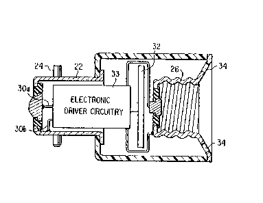
Figure 2 is a sectional view taken along the
direction of line II-II in Figure l;
Figure 3 shows the combination back-up light and
sound emitting device of the invention installed in the
back-up light socket of a vehicle tail light assembly;
Figure 4 shows a conventional tail light bulb; and
Figure 5 shows the electronic driver circuitry.
DETAILED DESCRIPTION OF THE PREFERRED EMBODIMENT
A preferred embodiment of the present invention
will now be described with reference to the
accompanying Figures, wherein the same reference
numerals will be used ~or the same elements throughout
the various v1ews.
Referring to Figure 3, a vehicle 2 has a tail
light assembly 4, including a~back-up light portion
6. The back-up light portion 6 includes a reflector 8
and a socket l0 having, for example, bayonet type slot
connectors for attachment of a bulb via bayonet type
projections of the bulb. Conventionally, a back-up
light bu1b 12 IFigure 4) has a base 14 and a pair of
transverse bayonet type projections 16 which cooperate
with bayonet type slots in the socket l0 for
:: :

3L3~ .
--5--
mechanically attaching the bulb to the vehicle tail
light assembly. Electrical connections associated with
the slots of the socket 10 provide electrical current
for lighting the bulb 12 when the vehicle is shifted
into reverse.
Referring to Figures 1 and 2, the combination
back-up light and sound emitting device of the
invention includes a housing 20 which can be of any
shape, but is hexagonal in section in the illustrated
embodiment. The housing has a base 22 similar to the
base 14 of the bulb 12, and also includes bayonet type
projections 24 corresponding to the bayonet type
projection 16 of the bulb 12.
At the end of the housing opposite the base, the
housing supports a~conductive socket 26 which accepts a
smaller size of light bulb which is of equal brightness
(lumens), which is readily available to the consumer.
The socket 26 is~electrically connected to socket 22
via wires 30a and 30b to provide electrical continuity
between the back-up light socket 10 and the socket 26.
An electrically operated sound emitting device 32
is positioned within the housing 20. It is a piezo-
transducer consisting of a piezo electric ceramic
material sandwiched between two brass discs and
oriented transverse to the axis of the housing.
~:
:~ :
~ ~:
~:: : :
: :

~3~
--6--
An electronic driver circuit includes a sound
generating circuit 133 connected to the sound emitting
device 32 via a 300 ohm resistor 233 and a 2N3055 type
transistor 333, and via the PICO K7342 transformers
433.
Openings 34 are formed on the top of the housing
to permit sound to be emitted therefrom.
In order to install the combination back-up light
and sound emitting device of the present invention, the
conventional back-up light bulb 12 is removed by
twisting the bulb to disconnect the bayonet joint
connecting the bulb to the back-up light socket 10. The
combination back-up light and sound emitting device of
the present invention is then installed in exactly the
same way that one would install another bulb 12. That
i5, the base 22 is inserted in the socket 10 and the
device is twisted to make the bayonet connection. Upon
shifting the vehicle into reverse, electrical current
will be simultaneously supplied to both the sound
emitting device 32 and a bulb 12 mounted in the socket
26, so that both audible and visual back-up signals
will result.
According to other vaxiations, the bulb 28 could
be permanently attached to the housing 20, so that the
entire assembly could be disposed of as a unit. Of
:
course, other types of connectors besides bayonet type
:
, ~ ,

5~
--7--
connectors could be used. For example, a screw type
connection could easily substitute for the illustrated
bayonet type connections.
Obviously, numerous other modifications and
variations of the present invention are possible in
light of the above teachings. It is therefore to be
understood that within the scope of the appended
claims, the invention may be practiced otherwise than
as specifically described herein.

Representative Drawing
A single figure which represents the drawing illustrating the invention.
Administrative Status

2024-08-01:As part of the Next Generation Patents (NGP) transition, the Canadian Patents Database (CPD) now contains a more detailed Event History, which replicates the Event Log of our new back-office solution.

Please note that "Inactive:" events refers to events no longer in use in our new back-office solution.

For a clearer understanding of the status of the application/patent presented on this page, the site Disclaimer , as well as the definitions for Patent , Event History , Maintenance Fee  and Payment History  should be consulted.

Event History

Description Date
Inactive: Reversal of expired status 2012-12-05
Time Limit for Reversal Expired 2009-07-24
Letter Sent 2008-07-21
Inactive: IPC from MCD 2006-03-11
Inactive: Reversal of will be deemed expired status 2004-11-04
Letter Sent 2004-07-21
Grant by Issuance 1992-07-21

Abandonment History

There is no abandonment history.

Fee History

Fee Type Anniversary Year Due Date Paid Date
MF (category 1, 5th anniv.) - standard 1997-07-21 1997-06-20
MF (category 1, 6th anniv.) - standard 1998-07-21 1998-06-17
MF (category 1, 7th anniv.) - standard 1999-07-21 1999-06-21
MF (category 1, 8th anniv.) - standard 2000-07-21 2000-06-19
MF (category 1, 9th anniv.) - standard 2001-07-23 2001-06-18
MF (category 1, 10th anniv.) - standard 2002-07-22 2002-06-17
MF (category 1, 11th anniv.) - standard 2003-07-21 2003-06-30
MF (category 1, 12th anniv.) - standard 2004-07-21 2004-07-20
2004-10-29
MF (category 1, 13th anniv.) - standard 2005-07-21 2005-07-20
MF (category 1, 14th anniv.) - standard 2006-07-21 2006-06-07
MF (category 1, 15th anniv.) - standard 2007-07-23 2007-06-07
Owners on Record

Note: Records showing the ownership history in alphabetical order.

Current Owners on Record
DESIGN TECH INTERNATIONAL, INC.
Past Owners on Record
MARK GOTTLIEB
Past Owners that do not appear in the "Owners on Record" listing will appear in other documentation within the application.
Documents

To view selected files, please enter reCAPTCHA code :


To view images, click a link in the Document Description column. To download the documents, select one or more checkboxes in the first column and then click the "Download Selected in PDF format (Zip Archive)" or the "Download Selected as Single PDF" button.

List of published and non-published patent-specific documents on the CPD .

If you have any difficulty accessing content, you can call the Client Service Centre at 1-866-997-1936 or send them an e-mail at CIPO Client Service Centre.


Document
Description 
Date
(yyyy-mm-dd) 
Number of pages   Size of Image (KB) 
Abstract 1993-11-01 1 21
Claims 1993-11-01 3 75
Drawings 1993-11-01 2 51
Descriptions 1993-11-01 7 192
Representative drawing 2001-11-29 1 13
Maintenance Fee Notice 2008-09-01 1 171
Fees 2004-07-19 1 33
Fees 2004-11-03 6 222
Fees 2004-10-28 2 69
Fees 2005-07-19 1 27
Fees 1996-06-16 1 68
Fees 1995-06-18 1 72
Fees 1994-06-15 1 70