Note: Descriptions are shown in the official language in which they were submitted.
\
~3~5~
METHO AND APPARATUS_FOR USE
-
IN_SEPARATING SOLIDS FROM. ~IQUIDS
.
Field of the Invention
05 This invention ls dlrected to method and apparatus ~or
separating ~olid~ from liquids ~ncludins the use o floc-
culating agents, such as polymers, and more particularly for
separating fine solids havin~ particle si2es of about 28
mesh by zero fro~ liguids 5uch as the reuse in a coal
; 10 preparation plant.
~ackqround of the Invention
Variou~ methods and apparatus for separating ~ine
particle size solids fro~ liquids are in u~e today. One
such method and apparatus i8 dlsclosed in U. S. P~tent No.
3,523,8ag to F. G. Eis. In thl6 patent a ~lo~cula~1ng agent
i8: in~roduced into a slurry which ls then di~charged ~rom a
: standpipe and it~ ~low is arrested by a baf1e and deflected
:
ou~wardly ~or ~ixing with thQ liquid in the tank. Xn Els,
: the slurry with the flocc~latinq~agent lncluded therein is
~: introduced into the tank in the midst o~ gentle ag~tation.
Another me~hod i~ disclosed in U. S. Patent No. 4,055,494 to
: ~ : R. C~. ~mm~tt, Jr. and assigned to Envirotech Corporation.
~; In the Emmett patent, th~ ~lurry to be &eparated ~g fed
25: successively through for ~ixing ~tages and a portion of the
, .
:
s~
flocculating agent is introduced and mixed in each ~tage
using a rotating blade. The Emmett patent does not ~tate
the type of agltation in the mixing sta~es~ However,
test~mony in a trial Amstar Corporation v~. Envirotech
~5 Corporation and Energy Fuels Nuclear, Inc., in the United
States District Court For The District of Utah Central
Division in a division published May 3, 1983 shows that
Envirotech ~ought to test a mean~ o~ mlechanically ætirring
flocculant and slurry with sufficient force to produce
excellent ~loc formation but not so forceful as to destroy
flocs once for~ed~ J. Rosenbaum & 3. Clemmer, "Li~uid-
Solids 5eparations," in J. Clegg & D7 Foley, Uran~u~ Ore
Processing 172, ls8o (1958), ~"the ~locculant must b~
disseminated uniformly throughout th~ slurry without de-
: 15 grading th~ ~loccules. Intense agitation to di6tribute the
reagent for maximu~ effectiveness degrades the fragile
; floccùles, and thu~ defeats it~ own purpo6e."3 Th~ procsss
in each of Ei~ and Em~ett ~orm~ generally butterfly-like
floccules which tend to re~ult in cake which is relat~vely
wet and sticky when ~eparated out of the slurry.
summary of the Inven~ion
This invention relates to method and apparatu~ ~or
separating sol~ds in fine part$cle sizes from a liquid using
a flocculating agent, such as an activated polymer mixture,
in a zone o~ intense agitation. In accordance wi~h this
invention, the floccules are nok ~ragile but are very ~trong
~: and wh~n th solids comprise a 28 mesh by zero r~fuse pro-
duced in a coal processing plant are relatively ~all and
generally bead-like in shape and which, when they are
separated ~rom th~ 61urry, result in a cake that i~ rela-
tively dry and Pirm. In ~n embodim~nt o~ the ~nv~ntion, ~8
illustrated speciflcally in this application, thia ~ accom-
plished in a separate unit of a coal preparation pl~nt
05 process. It i~ under~tood that a coal prepar~tion plant i~
used for purposes of description only and that the ~nvention
is applicable ~or the separation o~ any kind o~ sol~ds from
a slurry while using a flocculating agent.
In one embodiment of the invention, a ve6sel having at
least one processing chamber i~ provided. Th~ proces6ing
chamber has a peripheral outer wall portion extending for
360 degrees about a central vertical axi~ and ha~ an inl~t
opening in a lower portion thereof and an outlet portion in
an upper portion thereo~. When the process is ln operatlon,
: 15 a substantially const2nt volume of solids, flocculating
agent and liguid i~ maintained ln the processing chamber. A
fir~t slurry comprisiny solid~ in a l~quid i~ introduced
into th~ processing chamber through the inlet opening. A
~locculating agent, such a~ a dilute mixture of an activated
polymer, is introduced into the fLrst ~lurry while in the
processing chamber. Means are provided to create forces ln
the process~ng chamber to cause movement of the ~lurry and
th~ ~locculating agen in a substantially contLnuous path
from the inlet opening to the ~utlet opening. The ~ubstan-
tially continuous path comprise~ a plurality of ad~acentgenerally vertical ~piral portions extending in a clrcu-
latory direction through an arc less than ~60 degrees. The
; amount of the created ~orces necessary to cause the movement
through the ~ubstantially continuous path al~o causQ3
turbulent flow of t~e combined first slurry and ~loccul~ting
~3~5S~3
agent during the movement over the substantially continuous
path. During the movement through the substantially
continuous path, the flocculating agent acts on the solids in
the first slurry to change the solids into floccules. While
the size and shape of the floccules may vary, the process
when used in a coal processiny plant produced floccules that
appeared to be relatively small and bead-like in
configuration.
In one aspect the invention provides an apparatus for
continuously flocculating a slurry of particles, comprising a
slurry processing tank for receiving a slurry of particles to
be flocculated, a flow separator disposed within said tank,
flocculant delivery means for delivering a flocculating agent
to the tank and a rotatable agitator arranged below the flow
separator, said agitator comprising a plurality of agitating
members extending beyond the flow separator, whereby the
agitator is adapted to continuously circulate the slurry in a
recirculating flow pattern downwardly through the flow
separator, and upwardly and circumferentially outside a
cylinder throughout the slurry processiny tank thereby to
create a zone of intense mechanical agitation of the slurry
material and the flocculating agent.
In a further aspect the invention provides a method for
continuously flocculating a slurry of particles r comprising
feeding a slurry of particles to a slurry processing tank,
said tank having a flow separator disposed therein,
delivering a flocculating agent to the tank and subjecting
the slurry and the flocculating agent to intense m~chanical
agitation by means of a rotatable agitator arranged below the
flow separator and having a plurality of agitating members
extending beyond the flow separator, whereby said agitator
continuously circulates the slurry in a recirculating flow
pattern through the flow separator, and upwardly and
circumferentially outside a cylinder throughout the slurry
processing tank to form floccule particles.
'q''~
~3~5~
Fig. 1 is a schematic illustration of a flow diagram of
a coal processing plant incorporating the invention;
Fig. 2 is a schematic side elevational view of one
embodiment of the invention;
Fig. 3 is a top plan view of a portion of Fig. 2;
Fig. 4 is a graph ill~strating the various degrees of
agitation;
Fig. 5 is a schematic side elevational view of another
embodiment of the invention;
,,
Fig. 6 is a top plan view of a portion of Fig~ 5;
Fig. 7 is a schematic side elevational view of another
embodiment of the invention;
Fig. 8 is a top plan view of a portion of Fig. 7;
Fig. 9 is a schematic side elevational view of another
embodiment of the invention;
Fig. 10 is a top plan view of a portion of Fig. 9;
Fig. 11 is an enlarged view with parts in section of a
means for distributing a flocculating agent;
,: :
Fig. 12 is a schematic side elevational view of the
components of this invention mounted on a common base; and
.~
,
:~ :
~' ,,
.
, '
~3Q~
Fig. 13 is a top plan view of Fig. 12.
In Fig. 1, there is schematically illustrated a flow
diagram of a coal processing plant comprising a conveyor 2
carrying run of the mine material and dumping the material
: ~: 10
: ~ .
~` 15
.
:: : :
5a
:
,
. ~ .
:
`
~3~ ,9
into a unit 4 wherein the ~aterial ~ ~epara ~d $nto a
greatsr than 28 mesh ~ize and a 28 me~h by zero siz~. Th~
greater than 28 ~e~h material i8 fed into the ~i~ 6 wherein
water i~ u~ed to separate the low ash coal ~rom r~use, 6uch
05 a~ rock, ~late and hi~h a~h disposable mat~r~l. The
separation is by ~pecific gravity with the coal flo~ting
aGro~s the ~urf~ce of the ~lg 6 and the re~use ~inking to
the bottom. Th~ low ash coal i~ ~eparated ~nd fed into ds-
watering screens 8 and then into a rail car 10. The refuse
10 iB taken out of the jig 6 by con~eyor 12 and tran~ported to
conveyor 14 and dumped into refuse truck bin 16.
The 28 me~h by zero size run of the mi~e material in a
water ~lurry is drained from the unit 4 and fed into float
cell~ 20 wherein the 28 me~h by zero size low a~h coal i8
~eparated out and fed into a fllter unit 22. ~ater and any
fine ~ize material contained therein i~ drained from the
dewatering 6creen 8 and i~ al~o f~d into the flo t cell~ 20.
The dewatered 28 ~e~h by zero low a6h coal 1~ tr~n~ferred
~rom the fllter unit 22 to the rail car 10. The 28 mesh by
zero refuse sink~ to the bottom of the float cell~ 20 and ts
transferred ln slurry form to a thic~ener/ clarifier 24.
The thicXened 28 mesh by zero re~use in slurry ~orm i~ fed
into a flocculator 26 wherein a flocculaglng agent i6
introduced into the ~lurry which i8 then sub~ected to
turbulent flow ~o a~ to for~ th~ 28 mesh by zero rafu~ into
floccule~ in a ~lurry and then ~ed into the re~u~ filter
Z8. The ~ilter cake compris~ng the floccul~ted 28 ~esh by
zero refuse i~ removed fro~ the filter and deposited ontG
; the greater than size 28 mesh refuse on the conveyor belt 14
~o be dumped lnto re~use truck bln 16. The refusis is dumped
from refuse truck bin 16 into trucks 30 and tran~ported to
go~ plle 32 wherein cats 34 push and l~vel out ~he refu~e in
the gob pile. The helght in the gob pile iB lnlti~lly 12
inches and is then compacted to 4.1 to 6eal the gob plle
05 ~rom air to prevent 6pontaneous gob pile fires.
In one operation, the ~lter unit 28 wa~ ~ilterlng the
refuse at a rate o~ about 7 tons per hour prior to the
installatinn of a flocculator 26 o this invention. A~ter
installation o~ the flocculator 26, the ~ilter u~it wa~
~iltering the refuse at a rate of abou~ 15 - 20 ton~ per
hour. Thi~ is s~gnlficant since i~ the f~lter un~t 28 ln
some cases cannot keep the ~olids pulled down ln the
thickener, the refuse filter 28 must be run a~ter the
~hifts. This means that there i~ no coarse re~use on the
15 conveyor 14 so that the 28 mesh by zero refu~e cannot be -.
intermixed with the coarse refuse and must qo to the gob
pile 32 alone which is not desirable. Also, in accordance
with this lnvention, the filter cake on filtering mean6 is
relatively firm and ~ry 80 that it i5 readily r~moved from
the filtering means and i8 in a move preferred co~dit~on for
depo6ition onto the gob pile.
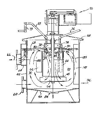
One embodiment of thi~ invention is illustrated in
Figs. 2 and 3 and comprise~ a vessel 36 having proce~sing
chamber 38 comprising having a bottom 4~ and a side wall 42.
A cylind~r 44 having an open top end 46 and an open bottom
~ end 48 i~ positioned in the processing chamber ~8 so that
;; the open bottom end 48 is spaced ~rom the bottom 40 of the
~:~ processing chamber 38. A bladed means 50, ~uch ~ an
impeller having vertical or ~lanted vanes or a propeller
having shaped blades or other ~imilar structur~ i~ loaated
,
ad~acent to and below ~he o~en bottom end 48. The bl~ded
mean3 50 iB connected to a 8haft 52 which can be rotated by
~uitable means 53~ The blades 54 of the bladed mean~ 50 ~re
designed so as to ~ove the materlal in the ~reas ad~Acent to
05 the impeller 50 in a downward and circlllar direction. The
rotation of the bladed means also induces the ~low of the
material within the cylinder 44 in suc'h a manner that the
level 9f the material within the cylinder 44 i~ below the
level o~ the other material in the proces~ing cha~bar 38.
The diameter o~ the tip of thQ blade~ 54 i~ ~lightly ~reater
than the in61de diameter of the cylinder 48. The outer
~urface of the cylinder 48 i6 provided with a plurality of
baffles 56 and the inner surface of the ~ide wall 42 ie
provided with baffles 58 to dampen the circular flow o~
materials in the processing chamber 38 and cause ~ ~plral ^.
circulating flow pattern as discussed below.
; An inlet 60 is located in a lower portion of ~he ~ide
wall 42 of the processinq chamber 38. A slurry 62
containing the ~olids to be ~eparated from the liquld is
introduced into the processing chamber 38 through the inlet
60. An outlet 64 i9 located in an upper portion o~ th~ ~lde
wall 42 of the processing ohamber 38. A ~lurry 66
com~r~sing the flocced bead-like floccules in a liquid ic
: extracted ~rom the proces~ing chambPr 38 through the outlet
64. ~hc rat~ of clurry 62 introduction and flocculating
~: agent introduction relative to the ra~e of slurry 66
: ~
extraction function to maintain the level 68 of the material
in the processing chamber 38. Because o~ the difference~ in
characteristics of the slurry 62 as compared to the
chaxacteristics of the slurry ~6, the volume lO of materl~i
in the processing chamber 38 compriæes many dlfferent typeæ
~ 3~
of slurries. It is noted ~hat the level 72 o~ the volu~e 70
o~ ælurrie~ within the cyli~der 44 i~ ~llghtly below the
level 68. A~ ~tated above, th~s 1~ causad by the ~nducement
o~ flow through the cyllnder 44 by the rotation of the
05 ~laded ~eans 50.
A blender 74 1~ located in the proc~6sing cha~ber 3
and spaced above the level~ 68 and 72 in th~ proces~ing
chamber 38. A pipe 76 i5 used to feed ~ flocculating agent,
such as an activated polymer mixture, having a conoentratlon
of about 0.5 per cent by weight into the blender ~4. A pipe
78 i8 used to ~eed dilution wat~r in~o tha blender 74.
~low meter 79 i5 used to control the amount of dilution
water added. Suitable maans (not shown) are provided within
the blender 74 ~o a~ to form a suitable intermixing of the
~locculating agent and the dilution water so that the
~locculating agent used in the proces~ ha~ a concentr~tion
of le~ than 0.05 per cent by weight. A plurality of tubes
xtend from the blend~r 74 downwardly in~ide of the
cylinder 44. The tube~ 80 are provided with nozzle~ 82
adjacent to and a~ove the lmpeller 50. Although the nozzles
: 82 are preferably located as shown, it i8 within the 6cope
of this invention to have the nozzles 82 located at any
height within the cylinder 44. The inlet 60 i6 located in
relation to the outlet 64 so that the circulatory portion of
the flow path of the materlal moving through the vessel
less than 360 degreas. In a pr~ferred embodiment of the
in~ention, thi~ circulatory portion o~ th~ ~low path i6
about 315 degree~. A drain 84 i~ located ~n tha bottom 40
for use when needed.
In accordance with thi~ invention, the m~tarial beiny
processed in the vessel ~lows in a continuous F.piral and
.~
~.3~i5~
circulatory path while being sub~ected to turbulent ~low.
When the process is in op~rat~on, a substantially con~t3nt
volume o~ olids, flocculating agent and llquid i~
maintalned ~n the v~ssel. A ~ir~t slurry compri~ing ~ollds
05 in a liquid i8 introduced into the vessel through ~n inlet
opening located in a lower portion of the ~essel. A
flocculating agent, such as a dilut~ mixture of an activated
polymer, is introduced into the firs slurry whi}Q in the
vessel. Means are provided to create ~orce~ in the veesel
to cause movement of th~ slurry and the floccul~ting agent
in a ~ubstantially con~inuous path from ths inlet opening to
an outlet open~ng located in an upper portion o~ th2 ve~sel.
The substantially continuoua path compri~e~ a plurality of
adjacent generally vertical ~piral portions extending in a
circulatory direction t~rough an arc les~ tha~ 360 degree~
The amount vf the created forces necessary to cau~e the
~ovement through the substantially continuou~ path al~o
cau~es tur~ulent flow of th~ combined first ~lurry ~nd
flocculatlng agent during ~ovement over the sub tRntially
co~tinuous path. During the movement through the
substantially continuous path, the ~locculating agent acts
on the ~olids in the first ~lurry to change the ~olids lnto
floccules. While the size and ~hape o~ the floccule~ ~ay
vary, the process when used in a coal processing plant
produced floccules that appeared to be r~latively ~mall and
bead-like in configuration.
In the embodiment o~ the invention illustrated ln Figs.
:~ 2 and 3, this ~ub~tantially ~ontinuou~ flow path i5 produced
by the combination of rotating the bladed means 50 50 that
the blades have a tip speed between about 300 and ~00 ~et
psr mlnute with the baf~les 56 and 58 cooperating to ~orm
13~
the combined spiral and clrculatory path. In order to
produce the proper inten5ity of agitation, the bladed mean~
50 should have a diameter which i8 between 30 and 60 p2r
cent o~ the inner diameter of the processlng chamber 38. In
05 the embodiment illustrated in Figs. 2 and 3, th~ turbulent
flow and flow path is obtained by rotating a bladed means 50
having 5 blades and a diameter of about 15 inches at a rate
~uf~icient to produce a t~p speed of each blade o~ about 500
feet per ~inute ~n a ve5sel havlng an inner dia~et~r o~
about 30 inches. The oylinder 44 ha~ an inner dia~ter o~
about 13 inches. The flocculating ayent ha~ a concentration
o~ about 0.025 per ce~t by weight. The height o~ the
material in the processing chamber 38 should be 60 to 85 per
cent of the diameter o~ the procesning chamber 38. Th~
15 slur~y introduced into the processing chamber 38 should ~ake -.
; at least three complete spiral paths while passing through a
~: circulatory path of about 315 degrees between the inlet S0
and the outlet 64. The ~piral path include~ downwardly
~oving portions within the cylinder 44 and vertically moving
portion between the cylinder 44 and the outer wall of the
procescing chamber. The flocculating agent acts on the
solids in the first Glurry during movement through the
substantially continuous path to change the solids into
floccul~s. A slurry comprising the floccules in a li~uid
move~ out of the vessel through the outlet opening and then
into ~ ~ilter unit wherein the floccules are ~eparated from
the liquid,
A graph in Fig. 4 depicts the various types of
agitation produced by rotating various sizes of bladed means
3~ in the embodiment illustrated in Figs. 2 and 3. Th~ graph
iB a plot o~ impeller diameter or impeller tip ~peed with
11
~3~.~S~
the horsepowex developed indicat~d by the number~ ~t th2
dot~. The graph o~ Fig. 4 hows that a zone o~ turbulent
~low 2Xi8tB when the blade~ have ~ tip speed of between
a~out 300 and 600 fe~t per ~inute.
os The ~ize of the flocculator depends on the amount of
material to be processed. In one e~bodiment o~ a
~locculator illustrated in Figs. 2 and 3, a slurry 62 havlng
a solids concentratlon of between about 35 and 45 per cent
by welght and preferably a concentration of ~bout 40 per
cent by weight i~ introduced into the proce~ing chamber 38
through inle~ 60 at the rate of between ~bout 100 ~nd 240
gallons per minute and preferably at a rate of about 150
gallon~ per minute~ A flocculating agent comprising ~
polymer mixture having a concentration of between 0.02 and
; 0.07 per cent by weight and preferably a concentration o~
about 0.03 per cent by weight is fed through the tubss 80 at
a t~tal rate o~ between about 25 and 35 gallons per minute
and pxeferably at a rate of about 30 gallon~ per mlnute. A
slurry 66 is extra~ted through the outlet at a rate o~
b~tw~en about 125 and 275 gallons per minute and prefer~bly
at a:rate of a~out 180 gallons per minute. The proceBsing
chamber 38 has an ~nside diameter o~ about 30 inches and the
cylinder 36 ha~ an inside diameter of about 12 inches. The
peller 50 has tip diameter of about 15 incheB and the
blad~ 54 are at an angle o~ about zero to the vertlcal,
The ba~les 56 extend outwardly ~rom the cylinder 44 in a
radial direction for a distance of about 6 inchss and are 3
~n nu~ber 6paced 1~0 de~rees apart. The baffle~ 58 extend
~ inwardly from the ~ide wall 42 in a radial directlon for a
: 30 distance of about 5 inches and are 3 in number ~paced 120
degrees apart. ~h~ impeller 50 is rotated at a rate
~ 3~6~
suffici~nt to produce a ~ip speed of between about 300 ~nd
600 feet per minute and preferably a tip spe~d of about 500
feet per ~ninute. Thus it is ~uite evident th~t ther~ i~ a
turbulent flow of the 61urry and flocculating ag~nt to
05 produce the floccule~. When the ~olids co~pri6e ~ 28 mesh
by zero x~fuse produced in a coal processing plant, th63
floccu7es are relatively ~mall and appear to be bead-l~ke in
shape .
Another embod~ment o:lF thi~ lnverltion 1~ illu~tralt~d ~ n
10 Figs. 5 and 6 and comprises a vessel 96 co~pri~ing ~
processing chamber comprising a proce~ing chamber 9~,
having a }: ottom lQ0 and a side wall 102 . A cylinder 104
having an open tc~p end 106 and an open bottom ~nd 108 is
positioned in the processing chambex 98 ~o that the open
bottom end 108 i8 spaaed from the bottom 100 of the -.
proces~ing chamber 98. The inside diameter of the cylinder
104 i greater than one-half the inside diamet~r o~ ths
proce~ing chamber 98. A bl~ded mean~ 110, such ~
propeller having ~haped blade~ located ad~acent to and
20 below the op~n bottom end 108. Th~ bladed means 110 i8
connected to a shaft 112 which can be rotated by suitable
mean~ 113. The blades 114 o~ the bladed means 110 are
designed ~o a~ to move t~e ~naterial in the area ad~acent to
th~ bladed means in a downward and circular direction. The
; 1 25 rotation of the bladed means also induces the flow o~ the
~` material with1n the cylinder 104 in such ~ m~nner th~t th~
level o~ the material within the cylinder 104 ~ b~low the
leve} of the other material in th~ processing chamber 98.
~rhe dia~eter of tha tip o~ the blades 114 i~ ~lightly
30 greater than the inside diameter of the cyllnder 104. The
outer surface o~ the cyl.~nder 104 is provided with a
~S~j~J`~
plur~lity o~ baf~les 116 ~nd the inner sur~ce o~ thQ slde
wall 102 i8 provided with baffle~ 118 to da~p~n the clrcular
flow o~ materlal~ ln the processlng chamb~r 98 ~nd cnuse
~piral circulating f low pattern as di~cus~e~l below .
05 An inlet 120 i~ located in a lower portion o~ the ~ide
wall 102 adjacent to the ~ottom 100 oI the proces~ing
chamber 98. A slurry 122 containing t:he ~olids to be
separated Prom the 1~ quid is introduce~ into the processing
chamber 98 t~ rough the inlet 120, An outlet 124 iEI located
in the ~;ide all 102 adjacen~ to the upper portion of the
proc~s~ing chamber 98. A ~lurry 126 co~prising ~locc:ule~ in
a liquid i3 extracted fro~ the processing chamber '38 throu~h
the outlet 124. The rate o~ slurry 122 introductls~n and
~locculating agent introduction relative to the ratQ of
slurry 126 extraction functlon to maintain the level }28 of ^.
the ma~erial in the procesE~ing chamber 98. BecausQ og thE3
dif~erences in characteristicY of the ~lurry 127 ~ comp~red
to the characterist1cs of tha slurry 126, the vol~e 13~ of
materlal in the processing cham~r 98 compri~es many
different types of ~lurries. It is noted that the level 132
of the volume 130 of material within the cylinder 104 i8
~lightly below the level 128. As stated above, thl~ is
caus~d by the inducement of flow through the cylinder 104 by
the rotation of the bladed ~neans ~10.
A blender 134 ls located in the processing cham~er 98
and spaced above the levels 129 and 132 in the proces~ing
cha~b~r 98. A plpe 136 i8 used to ~eed a ~locculating
agent, such as an activated polymer mixture, having a
concentration of about 0.5 per cent by weight into th~
blender 134. A pipe 138 is used to feed d.tlution water lnto
the blender 134. A flow meter 13g i~ used to control the
~3~5~
amount of dilution water ~dd~d. Suitable m~n~ (not ~hown)
~re provided within t:h~ bl~nder 13 4 BO a~ to ~or~ ~ sultable
intern ixing o~ the flocculating agent and the dilution wat~r
so that the flocculating agent used in the proce~ has a
os concentration of less than 0. 5 per cent by welght.
plurality of tubes 140 extend fro~n t~e blender 134
downwardly inside of the cylinder 104. The tube~ 140 are
provided with nozzle~ 142 ad~acent to and bove the l~vel
132 o~ material in the cylinder 104u Although the nozzle~
142 are preferably located a~ ~hown, it 1~ withln th-a scope
of this invention to have th~ nozzles 142 located ~t any
height within the cylinder 104 and even submerged in the
~aterial wlthin the cyl ~ nder 104 . The lnlet 120 iEI loc~ted
in relation to the outlet 124 so that the circulatory
portion of th2 flow path of the material moving through the
vesiel is le B than 3 60 degrees . In a pre~rred embodlment
o~ th~ invention, this circulatory por ion o~ the ~low p~th
i~ about 315 degrees. A draln 144 is located in the botkom
loO for u~e when needed.
The embodiment of the invention illustrated in F$gs. 5
and 6 operate~ in a manner similar to the em~odiment
illustrated in Figs. 2 and 3 in that the material being
processed in the vessel flows in a continllous splral and
circulatory path while being ~ubjected to turbulent flow.
:: 25 ~nother embodl~ent of the invention is illu~tr~ted in
Fiys. 7 and 8 and comprises a vessel 156 having ~ ~irst
processing chamber 158 and a second processing chambar 1~0.
The ~irst processing chamber 158 has a botto~ 162, a side
wall 154 ~nd a top wall 166. The inner ~ur~ace 168 of the
6ide wall 164 i~ provided with baffleet 170 ~nd the bottom
8urrace 172 of the top wall 166 is provided with ba~fles
~3~55~9
174. A bladed means 176, ~uch a~ an ~mpeller haYing bl~ds~
178 which are at æero de~ree~ to th~ vertlcal, i~ locat~d in
a central portion of the fir~t proce~ing cha~ber 158 ~nd
~paced clo~er to the bottom 162 than to the top wall 16S.
05 The bladed means 176 i~ ~ecured to the~ 6haft lB0 Por
rotation therewith. Conventional mealls (not ~hown) are u~ed
~o rotate the shaft 180.
An inlet opening 182 ~ located :Ln a lower portion o~
the ~ida wall 164 o~ the proce~sing chamber 158. A ~lurxy
184 containlng th~ ~ol~d~ to be 6eparated ~ro~ the liquid i8
introduced into the processing chamber 158 through the lnlet
opening 182. An outlet opening 186 i~ located in a central
portion of the top wall 166. A pipe 188 extend~ through an
opening 190 in the side wall 164 and terminates in a nozzle
; 15 192 which iB ad~acent to but fipaced ~lightly from the p~th -.
o rotation o~ the tip of the blade 178. A flocculating
agent having a concentration o~ about 0.5 p~r cent by weight
1~ ~ed into a blender 194 throuyh a pipe 196. Dilution
water i~ ~ed into the ~lender 194 through a pipQ 198. A
flow mQter 200 controls the amount of dilution water~ As
will be described below, a ~lurry comprising ~olids in an
initial stage o~ flocculation in a liquid flows from the
first processing chamber 158 through the outle~ opening 18
into the second proce~sing chamber 160.
Th2 ~econd proce~sing ahamber 160 hns a bottom
compri~ing the upper surface 202 of the top wall 166, ~ side
wall 204 and a top wall 206. The inner surface 208 o~ the
side wall 204 i6 provided with baf~les 210 an~ the bottom
~urface ~12 of the top wall 2ns is provided with baffles
30 214. A bladed means 216, such as an impeller h~vlng blade~
218 which are at zero degr~es to thQ vertlcal, i~ located in
16
a c~ntral portlon o~ the ~econd proces $ng ch~ber 160 ~nd
is ~paced clo5er to the bottom 202 than to the top w~ll 206.
Th~ bladed mean~ 216 1~ secured to an exten~ion o~ the ~h~ft
180 for rotation therewith.
05 A slurry 224 comprising the solids in an inltial ~tage
of flocculation in a llquld i~ introduced lnto the
proces ing chamb~r 160 through the openin~ 18~. An outlet
opening 226 i~ loca~ed in a central portion of th~ top wall
206. A pipe 228 extend~ through an opening 230 ln th~ ~ide
10 wall 204 and ter~inate~ in a nozzle 232 which i~ adjacent to
but ~paced slightly from the path of rotatlon o~ the tip o~
the blade~ 218. A ~locculating agent having a concentration
sf about 0.5 per cent by weight is fed into a blender 234
through a pipe 236. Dllution water i8 fed into the ~lender
15 234 through a pipe 238. A flow meter 240 controls tha
amount o~ dilutlon water. A~ wlll be de~cribed below, a
~lurry 242 compri~ing floccule~ ln a liquid flow~ out of thQ
econd proceRsing chamber 160 through the outlet 226 lnto an
overflow well 244 ahd then out of the v~ssel 15fi through an
outlet opening. The ~lurry ~ tran~ported to a ~iltering
mean~ such as the refuse filter 28 wherein the floccules ~re
separated ~rom the liguid.
In this embodiment of the invent~on, the material being
proce~sed in each o~ the fir~t and econd proces~ing
; 25 chambers flowa in a continuou~ spiral and circu}~tory path.
However, as explained below, the amount of agltation i~
dif~arent ln each of the processlng chambers. When the
proce~s i~ ln operatlon, a sub6tantially con~tant volume o~
~olid~, flocculating agent and liqui~ i~ maintalned in the
~ir~t and ~econd processing chambers. In ~act, in the
3Q5i~9
e~bodiment illu6trated in Figs. 7 and 8, each of th~
processing cha~bers iB ~ubstantlally full~
In op~ration, th~ 6haft 180 i6 rotated ~o that th~
bl~ded mean~ 176 is al~o rotated. As the blades 17~ ~ove
05 through th~ volume of ~aterial ln the fir~t proces~lng
chamber, they lmpart downward and circular force~ on the
material in the vic~nity of their zone o~ rotatlon. These
~orce~ p}us the flow retarding forces produced by the
ba~fle~ 170 and 174 cau6e the volume o~ ~aterl~l ln the
0 ~ir~t procss~ing chamber 158 to move in a continuous sp~ral
and circulatory path. A flocculating agent, co~pri~ing
d~lute ~ixture og an activated polymer having a
concentration o~ less than 0~05 per cent by weight, i~
~prayed out of the nozzles 198 into the zon~ o~ the path of
blades 178 and is mixed with the 601ids and liquid fro~ the
slurry 184 and flows therewith in the continuou~ spiral and
circulatory path. During the movement in the contlnuous
~piral c~rculatory path th~ flocculati~g agent cau~e~ the
solid~ in the #lurry to advance into an lnitial Ptag~ 0~
flocculation. Th~ ~haft 180 is rotated at ~ rate ~uf~icient
~ to produce a tip epeed of each blade of less than 240 feet
: per ~inute, which causes only gentle agitation ln th~
material being proce~sed. A ~lurry 224 comprl~lng the
solids in the initial stage of ~locculatlon in ~ liquid
flow3 out o~ the ~irst processing chamber 158 ~nd into the
second proces~ing chamber 160.
The rotation of the ~ha~t 180 al~o rotate~ th2 blsded
mean~ 216. As the blades 218 move through the volu~e o~
material in the ~econd processlng chamber 15~, they impart
downward and circular ~orces on the material in t~le vlcinlty
o~ their zone of rotation. Since the blade~ 21~ ~lave
18
~.3~ ~ 5~
diameter ~ub~tantl~lly greater khan the dl~metQr o2 the
blade~ 178 and are rotated at the 8ame rate, ths tlp spQed
of each blad~ 218 i~ ~ub~tantially ~r~a er than the tip
speed of Qach blade 178 80 that the downward and clrcular
05 forc~s are al60 sub6tant~ally greater. The tlp ~peed o~
each blade 218 i6 about 500 feet p~r ~:lnute which cauee6
turbulent flow in the material being proces6ed in the second
processing chamber 160. A flocculating agent, compri~ing a
dilute mixture of an activated polymer having a
concentratlon o~ less than 0.05 per cent by weight, i~
spray~d out of the nozzles 232 into the zone of the path of
the blade~ 218 and is mixed wlth the ~lurry co~pri6ing the
solids in the initial stage o~ ~locculation. The downward
and circulatory forces produced by th~ bl~de~ 2~8 cooper~te
15 with the flow retaxding ~orce~ produced by the ba~fle~ 210 -.
and 214 to produce a con~inuou~ ~piral and circulatory path
~or the ~aterial being proce~ed ln the second processing
cha~ber 160. Th~ m~xed flocculating ag~nt and th~ ~olld~ ln
~ th~ initial ~tag~ og ~looculation flow in this ~piral ~nd
:~ 20 circulatory path and during thi~ movement the ~locculating
agent acts on the ~oli~s ln the initial ~tage of
~locculation to ~roduce ~loccules. A ~lurry 242 compri~ing
the f}occules in a l~quid:flows out o~ the ~econd processing
: cha~ber and into an overflow well 244 and then move~ out of
~ the vessel lS6 through th~ outlet opening 242 to a
: conventional ~ilter unit.
The flocculating agent used in the first pro~e~ing
chamber 158 i~ preferably c~tionic so as to cause the solids
to change into an initlal stage o~ ~locculation. Ths
~locculating agent used in the ~econd proca~sincJ c:ham~er 160
19
~3~
i~ prefQrably anionic ~o 3S to produce the de~ired
~loccul~s .
One embodl~nerlt of th~ ~ invention i8 illu~trated in
Fig~. 2 and 3 and comprise~ a vessel 236 having a proce~ing
05 chamber 238 con~pri~ing hav~ng ~ botto~ 240 and ~ side w~ll
~42. A cy~inder 244 haviTlg an open top end 246 and an open
bottom ~nd 248 i6 positloned in the processing ch~rob~r 238
so that the open bottom end 248 i~ ~paced ~rom the bottom
240 o~ the processing chamber 238. A bladed ~ean~ 250, ~uch
î O a~ an impeller having vertical or slanted ~ane~ or
propellar having 6haped blades or other ~i~sllar structurç~ i~
located ~d~acer~t to and below t~e open bottom end 248. Th~
bladed means 250 i~ connected to a sha~t 252 wh:Lch can be
rotated by ~uitable mean~ 253. The blade~ 254 of the bladed
15 mean~ 250 are de~ign~d 60 a~ to move the ~aterl~l ln the -.
ar~as ad~acent to the i~peller 250 in a downward and
circulzlr d~re tion. The rotation of the bl~ded ~ean~ al~o
induces the f}ow of the material within the cylinde~ 244 in
such a manner ~hat the level of the material within the~
;20 cylinder 244 is below the level of the other material in the
proce~sing chamber 238. The diameter o~ the tip of the
blades 254 ls ~lightly greater than the in~ide dia~neter of
the cylinder 248. The outer surface of the cylinder 248 i8
pro~rided ~ith a plurality o~ baffles 256 and the inner
25 ~ur~aca of l:he eide wall 24Z is provided with ba~les 258 to
dampen the oiLrcular flow o~ ~aterial~ in the proc~ssing
chamber 238 and cau6e a ~piral airculating ~ow pattern ~s
di~c:u~6sd below.
An inlet 260 i~ located in a lower portion oie the eide
30 w~ll 242 o~ the processing chamber 238. A slurr~lr :262
contalning the solids to be separated from the li~id i5
55~
lntroduced into the proces~ing chamber 238 through the inlet
260~ Arl outlat 264 i3 looated ln an upper portiorl o~ the
~ide wall 242 of the proces~ing chamber 238. A slurry 266
compri~ing the flocced bead-lik~ floccule~ in a liquid i8
05 extracted ~rom the proce~sing chamber 238 through the outlet
264~ Th~ rate of slurry 262 introduct:Lon and flo~c-ul~ting
agent introductlon relative to the rate of #lurry 266
~xtraction function to maintaln the level 268 o~ th~
material ln the proces~ng chamber 238. B~cau~e o~ the
di f~er~nce~ in c:haract~ristic~ of the lurry 262 a3 compar~d
to the characteristic~ o~ the slurry 266, the volume 270 of
mater~al in the processing chamber 238 comprises ~nany
dlfferent type~ OI ~lurrie~ ~ It ~ 6 noted that the level 272
v~ the volum~ 270 of ~lurrles within the cyllnd0r 244 i~
~lightly below th~ level 268. As ~tated above, thi~ ~8 -.~: aau~ed by the inducement of f low through the cyl ~ nder 2 4 4 by the rotatiorl oî the bladed means 110.
A blender 274 i~ located in the proces~ing chaTQb~r 238
; and ~paced above the level~ 268 and 272 in the proce~sing
chamb~r 238. A pipe 2~6 i8 used to feed ~ floccul~ting
agent, such a~ an actlvated polymer mixture, hav~ng a
concentration of about 0.5 per cent by welght into th~
blender 274. A pipe 278 is used to ~eed dilution water into
th~ blender 274. A f-ow meter 239 is u ed to control the
amount of dllution water added. Suitable ~eans (not ~hown)
: are provided within the blender 274 ~o a~ to form a ~uitable
interm1xing o~ the flocculating agent and the dilution u~ter
~o that the ~locculating agent used in the proce~ has a
concentration o~ between 0.02 and 0.07 per cent by weight.
A disper~ing mean~ i5 illustrated ~peci~iaally in Fig.
11 and comprise~ a di~k 280 which i~ mounted ~n the shaft
21
i5~
252 ~or rotation t~erQwlth- A plurality o~ nozzle~ 282 ~re
~o~med in the di2k 280. The di~k 280 rec~iVe~ the diluted
flocculating agent ~rom the blender 274 and di8trlbute~ it
outwardly through the nozzlea 282- The di~X i~ mounted on
05 the ~ha~t 252 ~o that when the disk 1~ rot~ted, th~ dilut~d
flocculating agent will ~low through t~he noz~le~ 282 and be
di~persed there~rom into the curtain of material ~lowing
from the le~el 268 tu the level 272. In thi~ ~anner, the
flocculating agsnt i~ w~dely di~persed in th~ ~lurry 80 ~g
to readily contact the solid~ therein. Th~ ~loccul~tlng
agent exits thQ no~zle~ 282 at a pres~ure o~ between about
10 and 2 0 pounds per square inch .
The embodiment o~ the lnvention illustrated ~n Figs. 9
- 11 operates in a manner ~imilar to the embodiment~ in
FiggO 2~ 3, 5 and 6 in that the material being proce~6ed i~ -
th~ ve~sel flows in a contlnuou~ 6piral and circulatory path
whilQ b~i~g aub~cted to turbulent flow. It iB noted that
th~ ~low of material in Fig~. 9 ~ illustr~ted as being
clockwis~ whlle the ~low of material in Figs. 2, 3, 5 and 6
ls eountercloekwise. Th~ reason for this i~ the loe~tion o
the inlet opening relative to the outlet opening. The
eirculatory portion o~ the continuous spiral and eirculatory
path i~ less than 360 degrees. In each of thQ embodi~ents
illustrated in Figs. 2, 3, 5 and 6 and 9 - 11, the
circulatory portion of the eontinuous splral ~nd circulatory
path 18 about 315 degrees.
In Fi~. 12 and 13, there i~ illustrated a co~plete
assembly for processing a ~lurry compri6ing ~olid~ in a
liquid into a ~ilter cake co~pri~ing ~loceule~ formed in
accordance with the inventive concepts in this appllcatlon.
A base 300 i~ provided ~or ~upportiny all o~ the de~ired
22
~3~S5i~3
~3uipment. A i~locculatillg un~t 302 i~ ~t~ilar to that
lllu~l:rat~d in Fig~. 9 - 11. Th~ ~lurry co~prlelng ~olids
in a lis~uid 1~ introduced into th~ vee~eel 236 throu~h the
lnlet opening 200 and the ~lurry compri~ing the ~loccules ln
05 a li~uid exits through the outlet opening 264. A Pil~erlng
unit 304, such a3 Peterson 8 ' - lo" x 4 di~k filter ma~k2t~d
by Peter~orl Filter Corporation, is mo~mted on the b~se 300.
The slurry oomprising the ~loccule~ in a lisauid :18
introdu::ed into th2 filter unit 304 throu~h the mean~ 30~
10 and i~ processed in a conventional ~anner and ~ ~lter cake
iB diRcharged through the mean~ 3 08 . A wet ring vacuum pump
310 15 Also mounted on the ba~e 300 and i~ used to E~upply
the vac:uum required for the operation of the filtering unit
304. Aleo mounted on the base 310 are a device ~otor 312, a
discharqe ~ilencer 314, a f iltrat~ pump 316 snd other
a~ce3sories. The ba~e 300 iB 20 feet long and 10 feet wid~
and the li~1:ing weight ~ ~pproximately 20,400 ~ound~ ~30
~: that the co~plete a~embly ~ay be readlly trarlsported.
- ~t i~ contemplated that the inventive concepts herein
2 0 descrlhed may be variously otherwise embodi~d and lt ~8
lnterlded that the appcnded ela ims be construed to lnclude
~; alternat1vs embodim~nts oî the invention ~xcept in~o~ar a8
1 imited ~y the prior art .
:: ~
.
23