Note: Descriptions are shown in the official language in which they were submitted.
130S9~8
A method of and a device for leading a web moving
between two wires on to a desired wire
This invention relates to a method of guiding a
web on to a desired wire in a paper machine or the
like, wherein the web moves essentially in parallel
with a first wire and a second wire over a part of the
length of the wires in such a manner that the web is
positioned between the wires and makes contact with
both wires, whereafter the wires are arranged to part
from each other, and the web is detached from one of
the wires at a parting point of the wires and caused
to follow the other wire by exposing it to a vacuum at
least at the parting point through the wire which it
is to follow. The invention is also concerned with an
arrangement for leading a paper web on to a desired
wire.
Within the range of action of or immediately
after the formers of paper or paper board machines or
anywhere where it i8 necessary that the web follows a
desired wire, the passage of the wire has previously
been controlled by means of suction boxes or suction
rolls having straight or arched cover pieces. This
kind of solution is known e.g. from U.S. Patent Speci-
fication 4,623,429.
U.S. Patent Specification 4,623 429 discloses a
solution in which a web formed on a first wire of the
former is transferred on to a second wire by means of
a suction roll positioned within the loop formed by
the ~econd wire. A vacuum in the suction roll detaches
the web from the first wire so that it is transferred
on to the second wire.
In solutions known from the prior art it cannot
always be ensured that the web passes on in a con-
trolled manner; on the contrary, the web may start to
~305978
flutter after a point at which the wires part from
each other, which easily leads to the breaking of the
web. This, of course, causes unnecessary costs.
The object of the invention is to improve
the detachment of the web from between two wires on
to a desired wire and to prevent the flut-tering of
the web after the parting point of the wires. In the
invention this is achieved by abruptly changing the
direction of travel of at least one of the wires at
the parting point of the wires so that the directions
of travel of the wire portions at opposite sides of
the parting point are at an angle with respect to
each other.
By means of the solution according to the
invention, a web which follows one of the wires at
the parting point of the wires is detached from the
other wire essentially linearly, whereby the
detachment takes place abruptly immediately after the
parting point and the web follows the desired wire.
In this way, the web does not tend to flutter but
follows the desired wire neatly and evenly.
Correspondingly, the liability to breakage of the web
is decreased and thus unnecessary stoppages become
fewer.
Therefore, in accordance with the present
invention, there is provided a method of guiding a
web onto a desired wire in a paper machine, wherein
the web is first guided between a first wire and a
second wire so as to contact both wires and to be
moved along a length of the wires in a parallel
arrangement with the wires, whereafter, the wires are
arranged to part abruptly from each other at a
parting point by a shoe having a surface which is
positioned adjacent to one of the wires. The surface
comprises two planes forming a distinct angle and
intersecting to form a line in the surface. The line
defines the parting point. The wires and the web are
; ~ ,~ .~.
",
~3059~8
2a
arranged to move in the parallel arrangemen-t along
one of the planes of the surface and then to part
from each other at the parting point. One of the
wires is arranged to follow along the other plane of
the surface after the parting point so that the
direction of travel of one of the wires is abruptly
changed at the parting point, and the web is detached
from the first wire, and caused to follow the second
wire by applying a vacuum, through the second wire,
to the web at the parting point.
Also in accordance with the present
invention, there is provided an arrangement for
leading a web onto a desired wire at a parting point
of two wires in a paper machine which comprises at
least a first wire and a second wire arranged to move
essentially in parallel with each other over a part
of their length and to part thereafter so as to move
away from each other. Means are provided for guiding
the wires, whereby the web to be led between the
first wire and the second wire will be moved
therewith over the parallel length thereof in such a
way that the web will simultaneously make contact
with both wires. A separation means, located at the
parting point and adjacent to the guide means has a
surface which is positioned adjacent to one of the
wires. The surface comprises two planes forming a
distinct angle and intersecting to form a line in the
surface. The line defines the parting point. The
wires and the web are arranged to move in the
parallel arrangement along one of the planes of the
surface and then to part from each other at the
parting point. One of the wires is arranged to follow
along the other plane of the surface after the
parting point so that the direction of travel of one
of the wires is abruptly changed at the parting
point. Vacuum means are positioned at the parting
point of the wires and adjacent to the second wire so
~2
LILJ ~ ' --
13059`7~3
2b
as to draw the web agalnst said second wire so that
the web to be transferred onto the second wire once
the wires have been separated.
The invention will be described in more
detail in the attached drawings, wherein
Figure 1 is a schematical view of a former
section of a paper or paper board machine in which a
formed web follows a desired wire;
Figure 2 is a more detailed view of one
preferred embodiment of the invention shown in Figure
l; and
Figures 3, 4, and 5 are detailed views of
some further embodiments of the invention.
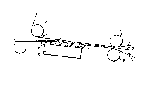
Figure 1 shows a former in a paper machine.
The former comprises a first wire 1 or an upper wire;
a web 2; and a second wire 3 or a lower wire which
the
i~ L~B~ .
~30S978
web 2 follows after a point at which the wires part
from each other. The upper wire 1 moves around rolls 4
and 5 and further around stretch and guide rolls (not
shown), thus forming an endless loop. In the embodi-
ment of Figure 1, the upper wire 1 is essentially
straight between the rolls 4 and 5. The lower wire 2
moves around rolls 6 and 7 and around other rolls not
shown, such as guide and stretch rolls, thus likewise
forming an endless loop. In addition, the lower wire 3
is led along the surface of a suction box 8, whereby a
cover piece 9 on the suction box is formed by cleats
10. The cleats 10 are shaped in such a manner that
planes extending in parallel to their upper surfaces
form a distinct angle ip the middle of the suction box
8. As a consequence, the direction of travel of the
lower wire 3 moving along the cleats 10 is changed ab-
ruptly at a line 11 extending through the point of the
angle, thereby deviating from the direction of travel
of the upper wire 1 at an angle CX . Due to a vacuum
effect exerted on the web 2 through the lower wire 3
by the suction box 8, the web 2 follows the lower wire
3, parting essentially abruptly, i.e., linearly, from
the upper wire 1.
The suction box 8 comprises means (not shown)
for creating a vacuum. Furthermore, cleaning and de-
watering means not shown are provided for the wires 1
and 3. All these are generally known.
Figure 2 is a more detailed view of the device
around the suction box 8. It appears from the figure
that the lower wire 3 moves along the surface of the
cleats 10 forming the cover piece 9 of the suction box
8, whereby the direction of the wire is changed at the
line 11 extending through the point of the angle of
the cover piece in such a manner that an angle is
formed between a wire portion 3a before the point line
,. , ~
1305978
11 and a wire portion 3b after the line 11.
The upper wire 1, after having been passed from
the roll 4 to the suction box 8 in parallel with the
lower wire 3 with the web 2 positioned between the
wires 1 and 3, continues its movement in the same di-
rection after the line 11, so that it does not any
longer make contact with the web 2 after said line.
In the embodiment of Figure 3, the point line
11 is formed by a leading edge of the cleat 10 seen in
the direction of travel of the web.
In the embodiment of Figure 4, in turn, the
point line is formed by a trailing edge of the cleat
10 .
In the embodiment of Figure 5J the direction of
travel of the lower wire 3 is essentially straight;
the upper wire 1, instead, is caused to change its di-
rection of travel abruptly by means of a separate shoe
12. A cover piece 13 on the shoe 12 is shaped so that
it comprises two slide surfaces which are at~an angle
with respect to each other. The upper wire I thereby
changes its direction of travel at a Iine 14 extending
through the point of the angle formed by the surfaces,
thu8 parting from the web 2 and the lower wire 3,
which reached the 8hoe 12 in parallel therewith.
By changing the direction of travel of~ at least
one wire abruptly according to the invention, the web
can be transferred reliably and evenly by means of a
single ~uction box. Irrespective of whether a suction
box is u~ed~ as a~ shoe for changing the direction or
whether a separate shoe positioned opposite to a suc-
tion box is used, the suction box is preferably con-
8tructed by mean~ of cleats. The 9uction box is there-
by less liable to clogging than conventional ~uction
boxes.`
In place of straight shoe surfaces, it is poss-
,
: ~ ,
,
,,. ~ ., ,,..,~, ....,... ,.. ,..~, ...
.. , :
1305978
ible to use surfaces arched to some extent, wherebyinstead of a plane, the wire moves along a surface
within the area of the shoe. Essential is, however,
that the shoe comprises a distinct edge at a point
where the wires are to be parted. The edge is formed
along a line defined by the point of an angle formed
between the surfaces along which the wire moves before
and after the parting point. Correspondingly, the
cover piece or the cleats of the suction box can be
dimensioned according to the same principle.
Even though it has been mentioned above that
the first wire is the upper wire and the second wire
is the lower wire, the invention is not restricted to
this position of the wires but_ the direction of the
wires can be as desired. Furthermore, the web can be
passed on together with either wire or as a free
transfer. The invention is equally suitable for use in
paper and paper board machines as well as in other
machines operating in a similar way. Instead of ab-
ruptly changing the direction of travel of one wire
only, it is possible to change the direction of travel
of both wires.
.