Language selection

Search

Patent 1306704 Summary

Third-party information liability

Some of the information on this Web page has been provided by external sources. The Government of Canada is not responsible for the accuracy, reliability or currency of the information supplied by external sources. Users wishing to rely upon this information should consult directly with the source of the information. Content provided by external sources is not subject to official languages, privacy and accessibility requirements.

Claims and Abstract availability

Any discrepancies in the text and image of the Claims and Abstract are due to differing posting times. Text of the Claims and Abstract are posted:

  • At the time the application is open to public inspection;
  • At the time of issue of the patent (grant).
(12) Patent: (11) CA 1306704
(21) Application Number: 1306704
(54) English Title: COMPOSITE SHIPPING CONTAINER
(54) French Title: CONTENANT D'EXPEDITION COMPOSITE
Status: Expired and beyond the Period of Reversal
Bibliographic Data
(51) International Patent Classification (IPC):
  • B65D 77/06 (2006.01)
  • B65D 19/20 (2006.01)
(72) Inventors :
  • VOORHIES, JOHN, JR. (United States of America)
(73) Owners :
  • HOOVER GROUP, INC.
(71) Applicants :
  • HOOVER GROUP, INC. (United States of America)
(74) Agent: MACRAE & CO.
(74) Associate agent:
(45) Issued: 1992-08-25
(22) Filed Date: 1988-03-14
Availability of licence: N/A
Dedicated to the Public: N/A
(25) Language of filing: English

Patent Cooperation Treaty (PCT): No

(30) Application Priority Data:
Application No. Country/Territory Date
028,865 (United States of America) 1987-03-23

Abstracts

English Abstract


ABSTRACT OF THE DISCLOSURE
A composite disposable one-way container comprising an outer
container of rectangular shape having upright continuous side walls and a
substantially flat top wall formed of corrugated paper material. A
unitary blow molded plastic inner tank having thin side walls is
positioned upright inside the outer container so that the outer container
maintains the inner tank in its upright position when the tank is filled
with a liquid to be transported. A pallet member has a flat top
supporting surface on which the outer container and the inner tank are
supported.


Claims

Note: Claims are shown in the official language in which they were submitted.

THE EMBODIMENTS OF THE INVENTION IN WHICH AN EXCLUSIVE
PROPERTY OR PRIVILEGE IS CLAIMED ARE DEFINED AS FOLLOWS:
1. A composite disposable one-way container having
vertical stacking capabilities comprising:
a. a pallet member having a top surface and
depending legs spaced apart to enable extension of
fork lift tines therebetween,
b. an outer container of rectangular shape
having a rectangular bottom wall supported on and
secured to said pallet top surface,
said outer container having upright
continuous side walls and a substantially flat top
wall formed of corrugated paper material,
said top wall having a central fill opening
and one of said side walls having a discharge
opening located adjacent said bottom wall, and
c. a unitary blow molded plastic inner tank
positioned upright inside said outer container and
having side walls sufficiently thin to prevent said
tank from being self supporting, said tank having an
inlet fitting extending into said container fill
opening, and a discharge fitting extending into said
container discharge opening,
said container side walls being of multi
layer construction to maintain said tank in an
upright position in said container when the tank is
filled with a liquid to be transported, and said
container top wall being of similar multi-layer
construction to enable two such containers to be
stacked two high.
2. The container according to Claim 1 wherein said
tank and outer container are configured to provide an air
space therebetween in the empty condition of said tank.

Description

Note: Descriptions are shown in the official language in which they were submitted.


~L3~
COMPOSITE SHIPPlNG CONTAIN~R
ackground of the Invention
Liquid material in bulk form is commonly stored and transported
in a varlety of large containers the most common being the conventlonal
fifty-five gallon drum. The disadvantages in the drum are related to the
inefficient storage space of cylindrical containers, the necessity for
rPturning the drums empty, and the necessity to invert the drum for
discharge purposes~
In recent years, a metal container of cublc ~hape and containing
an inner polyethylene tank has provided an advantageou~ alternative to
the fifty-five gallon drum. However, in the metal and polyethylene
composite container, separation of the inner tank from the outer metal
container is difficult. Such separation is required after the container
has been used and it is desired to re-cycle the container materials. It
is also desirable from a cost standpoint to eliminate the necessity for
metal in the container.
It is an object of the present invention, therefore, to p~ovide a
composite shlpping container whlch has the advantage of the cubic
configuration but in addition overcomes the disadvantages re~ulting rom
the necessity of the metal 6upport for the polyethylene tank In past
containers of this configuration.
Summary of the ~
The compo~ite ~hipping container of thls invent~on consists of a
disposable outer container of rectanyular shape havirlg a rectangular
bottom wall, upright continuoug side walls and a aubstantlally flat top
wall. All of the walls are formed of a corrugated paper material that is

-` ` . ~3Q6~)4 ~i'
less expensive than metal but is 6ufficiently strong to ~ccompli~h the
purposes of this invention.
A unltary blow molded plastic inner tanlc is positioned upright
inside the outer container. The slde walls of the tanks are sufficiently
thin to prevent the tank from being self supporting. The tank also has
an inlet ~itting extending into the container fill opening and a
discharge fitting extending into the container di6charge opening.
r~ ~ The outer container is mounted at its bottom wall on a pallet
member which has depending legs enabling extension of forklift -t~e~
therebetween to facilitate handling of the container. The container side
walls, being of multi-layer construction, maintain the plastic tank in an
upright position in the container when the tank is filled with a liquid
to be transported and the multi-layer construction of the top wall
enables two such containers to be stacked two high.
The composite shipping container of this invention has the
advantage of belng a one-way shipper. In other words, the composite
container can be shipped one way with the container filled with a liquid,
and after the container has been emptied, the outer container can be
readily separated Prom the inner blow molded tank for subsequent
recycling of both the corrugated paper materlal and the polyethylene from
the tank. The one~way feature has obvioua advantages from a cost stand
poiTlt .
Further objects, features and advantages of the invention will
become apparent from a consideration of the following description and the
appended claim~ when taken in connection with the accompanying drawing in
which:
--2--

~3~C)~
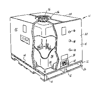
Fig. 1 i8 a perspectiYe view of the co~posite shipping container
of this invention with parts broken away for the purpose o~ clarityg and
Fig. 2 is a detail sectional view of the discharge fltting on the
tank and the associated portion o~ the containert and
FigO 3 is a horizontal sectional view of the container of this
invention,
With reference to the drawing, the composite shipping container
of this invention, indicated generally at 10, is illustrated in Fig. 1 as
including a pallet member 12 having a top surface 14 and depending legs
16 which are spaced apart to enable extension of forklift tines (not
shown) therebetween to facilitate moving and handling of the container 10
during transport and storage.
The container 10 also includes and outer container 18 of
rectangular shàpe having a rectangular bottom wall 20 supported on and
secured to the pallet top surface 14. The outer container 18 also has
upright continuous side walls 22 and a substantially flat top wall 24.
All of the walls 20i 22 and 24 are formed of a corrugated paper material
which is readily available from corrugated box manufacturing companies.
As shown in Figs. 1 and 2, the side and top walls 22 and 24 are of
multi-layer constructlon for a purpose to appear presently. The top wall
24 has a csntral filling opening 26 and one of the aide walls has a
discharge opening 28 located adjacent ~o the bottom wall 20.
~ unitary blow molded plastic inner tank 30 of very thin wall
construction is positioned upright inside the outer eontainer 18 so that
a top fill eap 32 on the tank 30 projects into the opening 26 in the top
wall 24 and a bottom discharge fitting 34 on the tank 30 extends lnto the
discharge opening 2B. The corners and edges o~ the tank 30 are rounded
--3--

~3~6~0~ ~
,
as shown in Figs. 1 - 3 and the tank 30 is nested at its lower end in a
styrofoam pad 35 of rectangular ring shape. The multi-layer construction
of the container slde walls 22 maintains the tank 30 in an upright
position in the container 18 when the tank is filled with a liquid to be
transported. The pad 35 also helps maintain the tank 30 in an upright
position in the container 18. The container top wall 24, being of
similar multi-layer construction, enables two such containers to be
stacked two hlgh wlth the pallet 12 on the upper container restlng on the
top wall 24 of the lower container.
Because of its cubic configuration, the container 10 can be
efficiently transported and stored and because of the location of the
discharge fitting 34 adjacent the bottom wall 36 of the tank 30, the tank
can be completely emptied with a minimum of har,31ing and manipulationO
support block 37 affixed to discharge fitting 34 supports the discharge
fitting 34 to also help keep the front vertical panel of tank 30 in a
vertical position. As shown in Fig. 3, the tank 30 iB spaced from the
container side walls 22 in the empty condition of the tank 30. This
enables the tank 30 to swell as it is filled with liquid thereby
displaceing the air in the space 39 between the tank 30 and the container
side walls 22. Thls air escapes the container 18 through siyht holes ~0
in the side walls 22. The provision of the space 39 enables the tank 30
to swell without damaging the container side walls 22.
Once the tank 30 ha~ been emptied, the shipping container 10 can
readily be disassembled because the corrugated paper outer container 18
can be manually removed from its position enclosing the plastic tank 30.
The outer container 18 and the tank 30 are thus readily saparated so that
they can be separataly recycled accordlng to processes appropriate for

~3~ 3'.~
the paper and plastic material8 from which the containers 18 and 30 are
respectively.formed.
The container 10 of this lnvention is thus readily us~able as a
one-way container to enable reduction in shipping c05ts.

Representative Drawing
A single figure which represents the drawing illustrating the invention.
Administrative Status

2024-08-01:As part of the Next Generation Patents (NGP) transition, the Canadian Patents Database (CPD) now contains a more detailed Event History, which replicates the Event Log of our new back-office solution.

Please note that "Inactive:" events refers to events no longer in use in our new back-office solution.

For a clearer understanding of the status of the application/patent presented on this page, the site Disclaimer , as well as the definitions for Patent , Event History , Maintenance Fee  and Payment History  should be consulted.

Event History

Description Date
Time Limit for Reversal Expired 2003-08-25
Letter Sent 2002-08-26
Inactive: Late MF processed 2001-08-31
Inactive: Late MF processed 1999-09-02
Inactive: Late MF processed 1998-09-16
Letter Sent 1998-08-25
Grant by Issuance 1992-08-25

Abandonment History

There is no abandonment history.

Fee History

Fee Type Anniversary Year Due Date Paid Date
MF (category 1, 5th anniv.) - standard 1997-08-25 1997-08-06
Reversal of deemed expiry 2001-08-27 1998-09-16
MF (category 1, 6th anniv.) - standard 1998-08-25 1998-09-16
MF (category 1, 7th anniv.) - standard 1999-08-25 1999-09-02
Reversal of deemed expiry 2001-08-27 1999-09-02
MF (category 1, 8th anniv.) - standard 2000-08-25 2000-08-02
Reversal of deemed expiry 2001-08-27 2001-08-31
MF (category 1, 9th anniv.) - standard 2001-08-27 2001-08-31
Owners on Record

Note: Records showing the ownership history in alphabetical order.

Current Owners on Record
HOOVER GROUP, INC.
Past Owners on Record
JOHN, JR. VOORHIES
Past Owners that do not appear in the "Owners on Record" listing will appear in other documentation within the application.
Documents

To view selected files, please enter reCAPTCHA code :


To view images, click a link in the Document Description column. To download the documents, select one or more checkboxes in the first column and then click the "Download Selected in PDF format (Zip Archive)" or the "Download Selected as Single PDF" button.

List of published and non-published patent-specific documents on the CPD .

If you have any difficulty accessing content, you can call the Client Service Centre at 1-866-997-1936 or send them an e-mail at CIPO Client Service Centre.


Document
Description 
Date
(yyyy-mm-dd) 
Number of pages   Size of Image (KB) 
Cover Page 1993-11-04 1 14
Abstract 1993-11-04 1 15
Claims 1993-11-04 1 41
Drawings 1993-11-04 1 45
Descriptions 1993-11-04 5 148
Representative drawing 2001-12-04 1 16
Maintenance Fee Notice 1998-09-22 1 178
Late Payment Acknowledgement 1998-09-25 1 171
Late Payment Acknowledgement 1999-09-10 1 172
Late Payment Acknowledgement 2001-09-19 1 172
Maintenance Fee Notice 2002-09-23 1 177
Fees 1996-07-17 1 47
Fees 1994-07-14 1 172
Fees 1995-07-13 1 38