Note: Descriptions are shown in the official language in which they were submitted.
~3~ 2~
--1--
PLASMA COLLECTION SET AND METHOD
Technical Field of the Invention
The invention pertains ~o the field of
plasma rollection. More particularly, the invention
pertains to the collection of plasma from volun~eer
donors at temporary sites, remote from medical
~acilikies, with portable lightweight equipment
capable of easy transpor~.
Back~round of the Invention
The collection of blood from volunteer
donors has become a very successful and very refined
activity. The development of single needle, single
use, disposable blood collection sets has provided a
safe, relatively inexpensive and donor comfortable
medium for use in the blood ollection process. Such
sets haYe made possible large-scale collection of
blood from volunteer donors at sites such as church
halls, schools or offices which might be remote from
medical facilities. The availability of volunteer
donors is im~ortant in that such donvrs tend to be
relatively healthy. In addition, they provide a
potentially much larger reservoir of dona~able blood
than i5 available rom the available group of paid
donors~
In recent years, the processing o whole
blood collected from donors has come to routinely
include separating the blood into therapeutic
components. These components include red blood
cells, platelets and plasma. Various techniques and
apparatus have been developed to facilitate the
collection of whole blood and the subsequent
separation of therapeutic components therefrom~
The collection of plasma from volunteer
donors, as opposed to the collec~ion of whole blood~
has not been nearly as successful. As a result, much
~k
~3~?~72~
. -2-
of the plasma now collected comes from paid donors,
as opposed to volunteer donors. It would be very
desirable to be able to upgrade the collection of
plasma so that it becomes a volunteer based activity
S to a much greater extent than it is currently.
One concideration in the collec~ion and
pLocessing of whole blood is the requirement that the
collecting ~nd the processing take place under
s~erile conditions. A second consideration involves
the requirement that processing take place under
conditions that maximize the storage life of the
blood components. Unless the processing take~ place
within a single sealed system, the permitted storage
duration and usable lifetime of the blood components
is substantially shortenedr Components processed
within a sealed system can be stored for four to six
weeks or longer before use. On the other hand, whole
blood or components thereof must be used within 24
hours if the system seal is broken.
One for~ of processing of whole blood into
various therapeutic components includes centrifuging
the blood so as to bring about the desired separation
of those components.
To promote the desired ends of sterile
processing within a single sealed system, dual member
centrifuges c~n be used. One example of this ~ype of
centrifuge i5 disclosed in United States Patent No.
Re. 29,738 to Adams entitled "Apparatus for Providing
Energy Communication Between a Moving and a
Stationary Terminal~" As is now well known, due to
the characteristics of such dual member centrifuges,
it is possible to rotate a container containing a
fluid, such as a unit of donated blood, and to
withdraw a separated fluid component, such ~s plasma,
into a stationary container, outside of the
~3~t~2~7
--3--
centrifuge without using rotating seals. Such
container systems can be formed as closed, sterile
transfer sets.
The Adams patent discloses a centrifuge
having an outer rotatable member and an inner
rotatable member. The inner member is positioned
wi~hin and rotatably supported by the outer member~
The outer member rotates at one rotational
velocity, usually called one omega, and the inner
rotatable member rotates at twice the rotational
velocity of the outer housing or two omega. There is
thus a one omega difference in rotational speed of
the two members. For purposes of this document, the
term ~dual member centrifuge~ shall refer to
centrifuges of the Adams type.
The dual member centrifuge of the Adams
patent is particularly advantageous in that, a~ noted
above no seals are needed between the container of
fluid being rotated and the non-moving component
~0 collection container. The system of the Adams
patent, provides a way to process blood into
components in a single, sealed t sterile sy~tem
wherein whole blood from a donor can be infused into
the centrifuge while the two members of the
centrifuge are being rotated.
An alternate to the apparatus of ~he ~dams
patent is illustrated in United States Patent No.
4,056,224 to Lolachi entitled "Flow System for
Centrifugal Liquid Processing Apparatus.~ The system
of the Lolachi patent includes a dual member
centrifuge of the Adams typeO The outer member of
the Lolachi centrifuge is ro~ated by a single
electric motor which is coupled to the internal
rotatable housing by belts and shafts.
~3~ 7
United States Patent No. 4,108,353 to Brown
entitled "Centrifugal Apparatus With Oppositely
Positioned Rotational Support Means" discloses a
centrifuge structure of the Adams type which includes
two separate electrical motors. One electric motor is
coupled by a belt to the outer member and rotates the
outer member at a desired nominal rotational velocity.
The second motor is carried within the rotating
exterior member and rotates the inner member at the
desired higher velocity, twice that of the ~xterior
member.
United States Patent No. 4,109,~55 to Brown et al.
entitled "Drive System For Centrifugal Processing
Apparatus" discloses yet another drive system. The
system of the Brown et al. patent has an outer shaft,
affixQd to the outer member for rotating the outer
member at a selected velocity. An inner shaft, coaxial
with the outer shaft, is coupled to the inner member.
The inner shaft rotates the inner member at twice the
rotational velocity as the outer member. A similar
system is disclosed in United States Patent No.
4,109,854 to Brown entitled "Centrifugal Apparatus With
Outer Enclosure".
Centrifuges of the type disclosed in the above
identi~ied Brown et al. and Brown patents can be
utilized in combination with a sealed fluid ~low
trans~er set of the type disclo~ed in United States
Patent No. 4,379,452 to DeVries. The set of the DeVries
patent incorporates a blood collection container that
has a somewhat rectangular shape similar to those of
standard blood collection sets. One embodiment of this
combi.ned system is the CS3000 cell separator ~ystem
marketed by Travenol Laboratories, Inc.
The CS3000 incorporates a dual member centrifuge in
combination with a sealed set of the type disclosed in
DeVries. This is a continuous pheresis system that
6~2'~
requires the donor to receive two needle punctures.
Such systems have been extensively used in blood centers
for plasma and platelet pheresis.
The CS3000 is a large and expensive unit that is
not intended to be portable. Further, the DeVries type
transfer sets are quite complex to install and use.
They are also an order of magnitude more expensive than
a standard, multi-container blood collection set.
A further alternate to the Adams structure i5
10 illustrated in United States Patent No. 4,530,691 to
Brown entitled "Centrifuge With Movable Mandrel". The
centrifuge of this latter Brown patent also is of the
Adams-type. However, this latter centrifuge has an
exterior member which is hinged for easy opening. When
the hinged upper section is pivoted away from the bottom
section, it carries the rotatable inner member along
with it.
The inner member supports a receiving chamber with
a spring biased mandrel which continually presses
against a sealed, blood containing, container positioned
within the receiving chamber. The system of this latter
Brown patent also discloses the use of two separate
el~ctric motors to rotate the inner and outer members.
The motors are coupled to a control system.
Another continuous centrifuge based system is
di~closed in Judson et al. United States Patent No.
3,655,123 entitled "Continuous Flow Blood Separator~.
The system of the Judson et al. patent uses two needles,
an outflow needle and an inflow needleO Whole blood is
drawn from a donor via the outflow needle~ The whole
blood fills a buffer bag. Blood from the buffer bag
drains, under the force of gravity into a centrifuge.
The system of the Judson et al. patent uses the
centrifuge to separate blood components. The plasma can
be collected in a container. The red blood cells can
be xeturned to the donor via the inflow needle. The
~ ,.
.' ;
'
~3~6~72~
system of the Judson et al. patent does not use a dual
member centrifuge. The system of khe Judson et al.
patent does not appear to be readily portable.
There thus continues to be a need for a method and
related apparatus of plasmapheresis which can readily be
used with volunteer donors at various temporary
locations. This method and related apparatus should be
usable by technicians with a level os skill commensurate
with the level of skill now found at volunteer-based
blood collection centers. Further, both the method and
related apparatus should be readily portable to locations
such as churches or schools where blood collection
centers are temporarily established. Preferably the
apparatus will be essentially self-contained.
Preferably, the equipment needed to practice the method
will be relatively inexpensive and the blood contacting
set will be disposable each time the plasma has been
collected from a single donor.
Summary_of the Invention
Various aspects of the invention are as follows:
A method of separating a selected component from a
fluid within a sealed system, a collection container of
which is rotated in a centrifuge while another portion of
which remains stationary, the method comprising,
providing a centrifuge, providing a sealed fluid
collection system with a ~luid filLed collection
container having an interior collection volume into which
extends a selectively oriented barrier member, inserting
the fluid filled collection container into a receiving
chamber of the centrifuge, rotating the collection
container at a predetermined rotational velocity thereby
separating the selected component from the remaining
fluid in the container by forcing the remaining fluid
into an outer annular region adjacent a rotating
peripheral wall of the chamber while simultaneously
collecting the separated component in an inner, ad~acent
annular region thereby emptying a central region of the
container, reducing the rotational velocity of the
.~,............ '
t7~'~
6a
collection container and fluid therein and blocking
movement o~ the fluid in the container with respect
t.hereto by means of the barrier member so as to minimize
mixing of the separated selected component with the
remaining ~luid, and withdrawing a selected portion of
fluid from the rotating collection container and into the
stationary portion of the system.
A method of separating first and second selected
components from a quantity of fluid comprising, providing
a fluid flow transfer sat having first and second disk-
shaped containers in fluid flow communication and a third
container in fluid flow communication with the first and
second containers, providing a centrifuge, filling the
first disk-shaped container with a predetermined quantity
of fluid, placing the first and second containers in a
rotatable receiving chamber of the centrifuge,
interposing a radially extending barrier into the first
container, rotating the chamber so as to effect
separation of the first and second components from a
residual fluid component, withdrawing the first and
: second separated components from the first disk-shaped
container without remixing them with the residual ~luid
component and at least partially filling the second disk-
shaped container with same, rotating the receiviny
chamber and separating the first and second components
from one another, and withdrawing one of the separated
components from the second disk shaped container into the
third container.
A fluid collection set, usable in the collection of
a quantity of fluid, and positionable in part in a
receiving chamber of a centrifuge ~or the purpose of
separating, by centrifugation, a selected fluid
component, the set comprising, a flexible, disk-shaped
collection container defining an interior collection
volume in which a quantity of fluid can be collected with
said collection container having a selectively curved,
sealed periphery, a fluid flow conduit with a proximal
end and a distal end, said proximal end in fluid flow
.:
~3a~
6b
communication with said interior collection volume, a
separated component container in fluid flow communication
with said distal end of said conduit with said disk-
shaped collection container rotatabl~ in the receivingchamber while simultaneously coupled to said compo~ent
container so as to accumulate the component separated
from the quantity of fluid rotated in the receiving
chamber with said proximal end of said fluid flow conduit
extending into said interior collection volume a
predetermined amount thereby forming an elongated,
radially extending barrier.
A fluid collection set, usable in the collection of
: a quantity of fluid, and positionabl~ in part in a
receiving chamber of a centrifuge for the purpose of
separating, by centrifugation, a selected fluid
component, the set comprising, a flexible, disk-shaped
collection container defining ~n interior collection
volume in which a quantity of fluid can be collected with
said collection container having a selectively curved,
sealed periphery said collection container formed of
first and second planar plastic members sealingly joined
along said curved periphery, a fluid flow conduit with a
proximal end and a distal end, said proximal end in fluid
flow communication with said interior collection volume,
a separated component container in fluid flow
communication with said distal end of said conduit with
said disk-shaped collection container rotatable in the
receiving chamber while simultaneously coupled to said
component container so as to accumulate the component
separated ~rom the quantity of fluid rotated in the
receiving chamber with said proximal end of said fluid
flow conduit extending into said collection container
through a selected region of said circular periphery.
16. A fluid collection set, usable in the collection of
a quantity of whole blood, and positionable in part in a
receiving chamber of a centriXuge for the purpose of
separating, by centrifugation, a selected blood
component, the set comprising, a flexible, plastic, disk-
~6~7Z~7
6c
shaped collection container defining an interior
collection volume in which a quantity of whole blood ~rom
a donor can be collected with said collection container
having a curved periphery, a fluid flow conduit with a
proximal end and a distal end, said proximal end in fluid
flow communication with said interior collection volume,
a separated component container in fluid flow
communication with said distal end of said conduit with
said disk-shaped collection container rotatable in the
receiving chamber while simultaneously coupled to said
component container so as to accumulate the component
separated from the quantity of blood rotated in the
receiving chamber with said proximal end of said fluid
flow conduit extending into said collection volume a
predetermined amount and attached to a region of the
collection container thereby forming a radially extending
barrier member positioned within said interior collection
volume.
A system for separation of a component from a fluid
comprising, means for centrifugation including a
rotatable receiving chamber, a fluid collection set,
usable in the collection of quantity of fluid, and
positionable at least in part in said receiving chamber
for the purpose of separating, by centriPugation, the
selected fluid component, said set inc:Luding, a flexible,
disk-shaped collection container defining an interior
collection volum~ in which the quantity of fluid can be
collected with said collection container having a
circular periphery, said collection container with the
quantity of fluid positionable in said receiving chamber,
a fluid flow conduit with a proximal end and a distal
end, said proximal end in fluid flow communication with
said interior collection volumP, a separated component
container in fluid flow communication with said distal
end of said conduit with said disk-shaped collection
container rotatable in the receiving chamber while
simultaneously coupled to said component container so as
to accumulate the component separated from the quantity
~ ~3~6~7~t7
6d
of fluid rotated in said receiving chamber with said
collection container formed of first and second planar
plastic members sealingly joined along said circular
periphery, a barrier member positioned within said
collection container between said sealed planar plastic
members, with said proximal end of said fluid flow
conduit extending into said collection volume a
predetermined amount thereby forming said barrier member.
A fluid collection set, usable in the collection of
a quantity of fluid, and positionable in part in a
receiving chamber of a centrifuge for the purpose of
separating, by centrifugation, a selected fluid
component, the set comprising, a flexible, disk shaped
collection container defining an interior collection
volume in which a quantity of fluid can be collected with
said collection container having a circular, sealed
periphery, and a generally radial container wall heat
seal line extending from said periphery toward a center
thereof, thereby blocking circumferential fluid flow
along said periphery, a fluid flow contact with a
proximal end and a distal end, said proximal end in fluid
flow communication with said interior collection volume,
a separated component containiner in fluid flow
communication with said distal end of said conduit with
said disk-shaped collection container rotatable in the
receiving chamber while simultaneously coupled to said
component container so as to accumulate the component
separated from the quantity of fluid rotated in the
receiving chamber.
A fluid collection set, usable in the collection of
a quantity of whole blood, and positionable in part in a
receiving chamber of a centrifuge for the purpose of
separating, by centrifugation, a selected blood
component, the set comprising, a flexible, plastic, disk-
shaped collPction container defining an interior
collection volume in which a quantity of whole blood from
a donor can be collected with said collection container
having a circular periphery with first and second opposed
`` 13t~6~'7
6e
walls of said container sealed together with a generally
radial heat seal line extending from a region of said
circular periphery toward a center thereof to form a
barrier to circumferential flow adjacent said periphery,
a fluid flow circuit with a proximal end and a distal
end, said proximal end in fluid flow communication with
said interior collection volume, a separated component
container in fluid flow communication with said distal
end of said conduit with said disk-shaped collection
container rotatable in the receiving chamber while
simultaneously coupled to said component container so as
to accumulate the component separated from the quantity
of blood rotatsd in the receiving chamber.
In accordance with another aspect of the invention,
a fluid collection set is provided which is usable in the
collection of a quantity of fluid. The set is
positionable in part in a receiving chamber of a
centrifuge. By centrifugation, a selected fluid
component can be separated from the fluid in the set.
~3¢~6~
--7--
Tne set includes a flexible disk-shaped
collection container. This container can be used to
accumulate a quantîty of fluid. The container can
have an elliptical or a circular periphery.
barrier member is positioned within the container to
impede the movement of the fluid within the container
during the centrifugation process.
Aiblood drawing cannula can be coupled to
the container by a draw conduit. The cannula can be
used to pierce the vein of a donor for the purpose of
filling the container with a unit of whole blood.
A fluid flow conduit, such as a section of
hollow tubing is attached at one end to the
disk-shaped collection container. The second end of
the conduit is attached to a second container in
which the separated component is to be accumulated.
The separated component container is positionable
outside of the centrifuge, at a fixed location~ while
the collection container is rotated within the
receiving chamber of the centrifuge.
In one embodiment of the invention, the
barrier member can be formed as an elongated
generally extending radial member. The collection
container can be formed of firs~ and second planar
plastic members which are joined, perhaps by heat
sealing, along the curved periphery.
The fluid can be for example, whole blood
collected from a donor. In this embodiment, the
blood collection container is positioned in the
receiving chamber of the dual member centrifuge. The
separated component can be, for example, plasma.
Subsequent to rotating the collection container in
the centrifuge, the ~eparated plasma can be pumped
into a plasma collection container exter~or to the
centrifuge.
6.~2t~
--8--
A method of practicing the invention
includes providing a dual member centrifuge. In
addition, a sealed 1uid collection system can be
provided. The fluid collection system has a
disk-shaped fluid collection container. The fluid
collection container is filled with a q~antity of
floid and ~hen is positioned within a receiving
chamber of the centrifuge.
The collection container is rotated at a
prede~ermined rotational velocity which results in
the separation of the selected component from the
remai~ing fluid in the container. During the
separating step, the separated fluid fills an inner
annular region within the disk-shaped container. ~n
outer annular regionO adjacent the interior
peripheral wall of the receiving chamber is filled
with the residual fluid in the container~ A central
region of the container is emptied of fluid during
the centrifugation process and collapses. As a
result, the container assumes a donut or toroidal
shape.
The separated fluid component can then be
with~rawn from the container. The withdrawing step
can include pumping the separated component from the
collection container into a component container.
In a preferred embodiment of the invention~
the disk-shaped container is rotated at a relatively
high speed, on the order of 4~000 rpm for 7-10
minutes to effect the separ~tion. The container is
then slowed during a 2 to 4 minute period tv about
1,000 rpm for the purpose of withdrawing the
separated componentO During the slow-down process
the generally radially extending ~arrier member
within the container blocks movement or sliding of
the fluid in the container with respect theretoO
:~3~ Z'7
g
In yet another embodirnent, first and second
components c~n be separated. The first and ~econd
~eparated components separate from the residual fluid
in a two stage process. Initially, both separated
components are mixed together. Over a period of
time, as the receiving chamber continues to rotate,
the two separated components will in turn separate
from each otherO
The system o the present invention is
particularly advantageous in that the donor
experiences only a single needle puncture as is the
case when donating blood. Furthe~, once the unit of
blood has be-en drawn, the donor is finished and can
leave. Finally, the transfer set should have a cost
comparable to the cost of currently available blood
collection sets.
Numerous other advantages and features of
the present invention will become readily apparent
from t~e following detailed description of t~e
invention an~ the embodiments thereof, from the
claims and from the accompanying drawings in which
the details of the invention are fully and completely
disclosed as a part of this specification.
Brief Descri~ion of the Drawin~s
Figure 1 is an overall system view
schematically illustrating a readily transportable
dual member centrifuge and fluid flow transfer set in
accordance with the present invention;
Figure 2 is a top plan view of a blood
collection container in accordance with the present
invention;
Figure 3 is a view in section taken ~long
plane 3-3 of Figure 2 illustrating the relationship
of the radially extending barrier member to the sheet
member~ of the container:
~3~ 6~2~
-10-
Figure 4 is a view in section taken along
plane 4~4 of Figure 2 illustra~ing the relationship
between the container forming sheet members and the
~irc~lar peripheral seal of the container;
Figure 5 is a schematic view illustrating an
alternate fluid flow transfer set in accordance with
the present invention;
Figure ~ is a enlarged view, partly in
section, ~f the receiving chamber of the centrifuge
of Figure 1 illustrating separation of a component
from a fluid in accordance with the present invention;
Figure 7 is an enlarged view, partly in
section o~ an alternate structure also illustrating
separation of a componen from a fluid in accordance
with the present invention;
Figure 8 illustrates schematically the steps
of a method of separating a fluid component in
accordance with the present invention; and
Figure 9 is an overall schematic view of an
alternate fluid flow transfer set and method of
separating first and second fluid components in
accordance with the present invention.
Detailed Descr ~ he Prefexred Embodiment
While this invention is susceptible of
embodiment in many different forms, there are shown
in the drawing and will be described herein in detail
specific embodiments thereof with the understanding
that the present disclosure i5 to be considered as an
exemplification of the principles of the invention
and is not intended to limit the invention to the
specific embodiments illustrated.
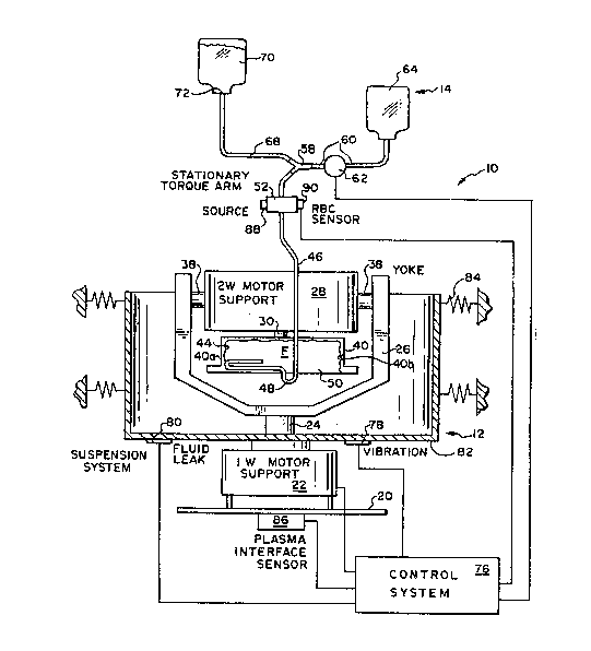
Figure 1 illustrates a readily transportable
system 10 in accordance with the present invention.
The system 10 includes a relatively light weight dual
'7
member centrifuge 12 and an associated fluid flow
transfer set 14.
The dual member centrifuge 12 is of the
Adams type having a stationary support 20 on which is
mounted a first motor 22. The first motor 22 has a
rotary output shaft 24 which rotates at a first
angular velocity conventionally referred to as one
omega. Fixedly attached to the rotary shaft 24 is a
yoke 26. The yoke 26 supports a second electric
motor 28. The electric motor 28 has a rotary output
shaft 30. The chaft 30 rotates at an angular
velocity twice that of the shaft 249 conventionally
referred to as two omega~ The motor 28 is pivotably
attached to the yoke 26 at pivot poin~s 36 and 38.
Affixed to the rotating shaf~ 30 is a
cylindrical receiving chamber 40. The receiving
chamber 40 is rotated by the shaft 30~ The chamber
40 has a cylindrical exterior peripheral surface 40a
as well as a cylindrical interior peripheral surface
40b. The chamber 40 supports and rotates a
collection container 44. The chamber 40 has an inner
diameter on the order of six inches and an internal
length on the order of two inches.
The collection container 44 is in fluid flow
communication via a flexible conduit 46 with the
remainder of the set 14. A proximal end 48 of the
flexible fluid flow conduit 46 extends into the
interior volu~e 50 of the containeL 44. The
container 40 can be filled with a quantity of fluid
30 such as whole blood provided by a donor.
The fluid flow conduit 46 is supported by a
stationary torque arm 52, The use of such torque
arms is well known ~o tAose skilled in the ar~ wi~h
respect to dual member centrifuges of the Adam~
~3~2~7
-12-
type. A distal end 54 of the fluid flow conduit 46
is coupled to a "y" junction member 580 A branch
ronduit 60 coupled to the junction member 58 is
physically coupled to a separated component pump 62.
The separated component could, for example, be plasma
and the pump 62 could be a plasma pump. The fluid
frow conduit 60 is also in fluid flow communication
with a sepa~ated component collection container 64.
The container 64 could be a standard plasma
collection container.
Also coupled to the junction member 58 is a
third fluid flow conduit 68. The ~luid flow conduit
68 is coupled to a red cell nutrient and preservative
~olution container 70. The solution in the container
70 is of a known type which provides nutrients to
packed red blood cells subsequent to the plasma
pheresis process. Contents of such solutions include
dextrose, sodium chloride, mannitol and adenine. One
appropriate solution is marketed by Travenol
Laboratories, In~. under the trademark ADSOL. The
container 70 is sealed with a frangible member 72
which can be broken at an appropriate point in the
plasma pheresis process.
The ~ystem 10 also includes a control system
76 which i5 coupled to the motors 22 and 2B. The
control system 76 receives feedback from vibration
and fluid leak sensors 78 and 80. The sensots 7B and
80 are fixedly supported by a stationary suspension
system 82. The ~ystem 82 can be connected to
resilient members 84 to s~abilize the centrifuge 12
during operation.
In addition, if desired, a plasma interface
sensor 86 can be provided which is in turn coupled to
the control system 76. The plasma interfa~e ~ensor
86 can be used to detect the location o the
':`. l
~3~'2~7
13
interface between the separated plasma and packed red
blood cells in the container 44 during the
centrifugation process. An appropriate interface is
disclosed in co-pending United States Patent No.
4,806,~52 entitled OPTICAL DATA COLLECTION APPARATUS
~D METHOD assigned to the assignee of ~he present
invention.
As an alternate, the dual member centrifuge 12 can
sense the presence of the plasma/red blood cell
lo interface in the tubing member 46 to 60. For example, a
source of radiant energy 88 could be attached to the
stationary torque arm 52. A sensing member 90 can also
attach to the stationary torque arm 52 displaced ~rom
the source 88. The conduit 46 extends between the
source 88 and the sensor 90. The sensor 90 detects a
plasma and packed red blood c~ll interface in the
flexible conduit 46 and the plasma in being pumped off
by the pump 62. A signal from the red blood cell sensor
90 indicating that the inter~ace has been detected is
al50 coupled to the control system 76 and can terminate
the plasma pheresis operation.
The source 88 and sensor 90 can also be positioned
; adjacent the tubing member 60.
Figures 2 4 illustrate the structure of the
collection container 44. The collection container 4~ is
disk-shaped and can be formed o~ first and second
plastic sheet members 44a and 44b. Plastic sheets o
the type normally used for blood collection o~ sets are
usable to ~orm the container 44. The first and second
plastic members 44a and 44b can be heat sealed together
at a circular periphery 100. The sealing o~ the
circular periphery ~00 can be brought about by
.4 ' "
~.3~;P672~7
--14-
radio frequency heat sealing or by means of heated
platens. Within the circular periphery 100 is
defined the interior collection volume 50. The
length of the diameter of the circular pe~iphery 100
is on the ~rder of 7 to 8 inches.
It will be understood, that while an
esSentially circular container 44 is illustrated in
Figure 2, the present invention is not limited to
circular containers~ It will be understood that a
disk-shaped container could also include a container
with an elliptically shaped sealed periphery.
The container 44 includes an elongated,
generally radially extending barrier member 102 which
extends into the interior region 50. The harrier
member 102 is formed by heat sealing together a
region of the sheet members 44a and 44b.
The container 44 includes a port 104 which
is in fluid ~low communication with the 1exible
fluid flow conduit 46. The container 44 a}so
includes a port 106. The port 106 is a filling port
used during the draw cycle when the donor is bleeding
into and filling the container 44. The port 106 is
also in fluid flow communication with a fluid flow
condui~ 10~. A distal end o~ the fluid flow conduit
108 can be connected to a draw cannula 110 intended
to be inserted into the vein of the donor.
The container 44 also includes a dispensing
port 112. The port 112 is closed with a pierceable
member and can be used to subsequently dispense the
30 remaining contents in the container 44 once the
pheresis process has been completed.
Figures 3 and 4 illustrate in section ~he
relationship between the barrier member 102 and the
sheet members 44a and 44b as well as the curved
peripheal seal 100 and the sheet member 44a and 44b.
~6~Z}~
-15-
Figure 5 illustates an overall view of the
fluid flow transfer set 14. The transfer set 14 can
be used to accumulate a unit of donated blood by the
same blood collection technicians as now use ~tandard
blood collection sets. Further, the cost of the set
14 should be comparable to th~ cost of current blood
cQllection sets.
In the em~odiment of Figure 5, the circular
container 44 has been replaced by an elliptical
disk-shaped container 45. The container 45 includes
the draw port 105 which is in ~luid flow
communication with the draw conduit 108. The draw
conduit 108 terminates at its free end in the cannula
110. The container 45 can be formed in the ame
manner as the container 44 by heat sealing the planar
sheet me~bers 45a and 45b along the elliptical
periphery 114 .
The container 45 also includes ~he port 104
which is formed in the elliptically shaped peripheral
wall 114. The proximal end 48 of the fluid flow
conduit 46 extends ~hrough the port 104 and
terminates in a section 120 in the interior volume
122 defined by the con~ainer 45. The section 120 is
: formed of a hollow tubing member which is in fluid
flow commurlication with the proxima:L end 48. In
addition, the section 120 is sealingly attached to
adjacent regions of the plastic sheet members 45a and
45b~, The sealingly attached member 120 thus forms an
inwardly extending, elongated barrier analogous to
the barrier 102 in the container 44. The proximal
end 4~ is sealed by a breakable cannula member 124
until the draw cycle has been completed~ The
proximal end 48 can be fixedly attached to the
exterior ~f the sheet member 45b at a suppor~ing weld
126.
.~3~ 7
-16-
A bushing 128 can be provided to slideably
engage the stationary ~orque arm 52 to prevent
abrasion and wearing vf the ~onduit 46 during the
centrifugation process. In addition, the source of
radiant Pnergy 8& and respective sensor 90 could be
positioned-adjacent a transparent region 130 of the
tubing member 60 for the purpose of sensing the
plasma/packed red blood cell interface at the end of
the pheresis processO Pump segment keepers 132 can
al~o be provided to restrain tllbing members 60 and 68
in position with respect ~o pumps such as the plasma
pump 62 which could for example be A peristalic pump.
Figure 6 illustrates the sys~em 10, and more
particularly the receiving chamber 40 with ~luid
filled container 44 therein partway through the
centrifugation process. The centrifugation process
takes on the order of 7-10 minutes at a speed of
about 4,000 rpm. During this time, the whole blood
in the container 44 is essentially separated into two
major components.
The heavier red blood cells accumulate in an
exterior annular region 140 adjacen~ the interior
peripheral wall 4Ob. Platelet poor plasma collects
in an interior annular region 142 as the plasma is
not as heavy as the red blood cells. An interface
region 144 develops between the exterior toroidal
region 140 filled with packed red blood cells and the
interior toroidal region filled with platelet poor
plasma.
During the high speed separation interval,
when the red blood cells are being forced into the
outer annular region 140, a central portion 44c of
the sheet member 44a i~ emptied of fluid. As a
result, that region collapses, as illustrated in
:~3~ 2~7
-17
Figure S, d~e to the effects o:E centrifugal forces
generated by rotation of the fluid.
After the 7 10 minute centrif~gation
interval has passed, the chamber 40 can be slowed ~o
about 1,000 rpm over a 2-4 minute interval. It has
been found that the bar~ier 102 is important during
the slow-down period to keep the ~luid within the
container ~om sliding and remixing again. By means
of the barrier member 102t the fluid i5 also forced
to slow down at the same rate as is the receiving
chamber 40. During the slow-down period, the packed
red blood cells stay in the annular region 140 and
the platele~ poor plasma tends to remain in the
interior annular region 142.
Once ~he slow-down interval has passed, the
platelet poor plasma can be withdrawn from the region
142 via the fluid flow conduit segment 120. The
segment }20 extends into the region 142 through the
seal 100. The member 120 in additiun to being able
to function as the barrier member as discussed above,
must extend far enough into the container 44 so as to
be located in the region 142 of platelet poor plasma.
It should be noted that the interface 144
could contain platelets which mig}lt be drawn off
25 subsequently after the platelet poor plasma in the
region 142 has be~n removed. The peristalic pump 62
can then pump the platelet poor plasma from the
region 142 into the container 64.
As the platelet poor plasma is withdrawn
from the region 142, the bag 44 will collapse
further~ The collapsed region 44c will extend toward
the interior peripheral wall 40b.
Figure 7 illustrates an alternate
construction of the container 44. The proximal end
48 of ~he tubing member 46 is coupled to a plasma
~3~6~2'7
withdrawal port 150 which is centrally located. In
the embodiment of Figure 7, the container illustrated
therein will require a separate elongated radially
extending barrier member as in Figure 2. Except for
the location of the plasma withdrawal port 150, the
container of Figure 7 functions essentially the same
way as does the con~ainer of Figure 6.
Figure 8 illustrates a batch method of
collecting platelet poor plasma in accordance with
the present invention. The method of Figure 8 is
suitable for use in connection with volunteer blood
donation programs. The dual housing centrifuge 12
will be relatively lightweight and is easily
transportable. Hence, it can be taken to the device
locations such as church basements and recreation
halls where blood donation programs are temporarily
set up.
In Figure 8a~ a donor is illustrated
donating a unit of blood B which is accumulated in
the bag 4~. The bag 44 i5 intergally attached to the
remainder of the set including the plasrna collection
container 64. As far as the donor is concerned, this
is merely a standard blood donation processO Once
the unit of blood ha~ been accumulated, the donor is
free to leave.
In Figure 8b the container 44 contains a
unit of whole blood B and has been uncoupled from the
donorO The draw conduit 108 has been sealed, for
instance~ by heat sealing. The ~rangible cannula 124
has been broken so as to place the container 44 into
fluid flow communication with the plasma accumulation
container 64. Figure 8c illustrates the blood filled
container 44 positioned in the receiving chamber 40
prior to the initiation of centrifugation.
S 6 7 2 7
-19-
Figure 8d illustrates the container 44
partway through the centrifugation process. In
Figure 8d the red blood cells have started to fall
way from the plasma into the annular region 140. The
platelet poor plasma is starting ~o accumulate in the
inner annu.lar region 142.
' Figure 8e illustrates the container 44
subsequent ~o the slow down s~ep and while platelet
poor plasma is being withdrawn from the region 142 by
means of the pump 62. The accumulated platelet poor
plasma is being collected in ~he container 64. As is
illustrated in Figure 8e, the central region 44c of
the container 44 is collapsing~
Figure 8f illustrates the container 44 from
which the platelet poor plasma has been removed or
: withdrawn and after the nutrient mixture in the
container 70 has been infused therein. The nutrient
mixture prolongs the life of the packed red blood
cells and provides a dilluting fluid to restore the
hematocrit to levels such that the concentrated red
blood cells can then be infused into a patient. Also
in Figure 8f, the container 64 of plate~et poor
plasma is illustrated sealed off and separated ~rom
the container 44.
In addition to being able to accumulated
platelet poor pla~ma in a collection container such
- as the container 64 it is also possible, using
another embodiment, to accumulate the platelets in a
separate container. Figure ~ illustrates a fluid
flow transfer set lS0, related apparatus and method
usable for this purpose~
The transfer set 150 includes a first,
disk-shaped container 152 such as the container 44 of
Figure 2. The container 152 is in fluid flow
35 co~munication via a conduit 154 with a second
~3~ '7
-20-
disk-shaped container 156. The container 156 can
also have a structure which corresponds to the
container 44~
A tly~ junction member 160 located in the
fluid flow conduit 154 provides a fluid flow path,
via a conduit 162, to a container 164. Initially the
c~ntainer 164 contains nutritive solution of the type
noted previously with respect to the container 70.
The container 152 is initially filled with
whole blood as illustrated in Figure 8a previously
discussed~ The set 150 is then mounted on a dual
member centriruge such as the centrifuge 12. The
collection container 152 and the second container 156
are both loaded into the receiving chamber 40. The
conduit 1S4 is brought out of the receiving chamber
to a stationary region outside of the centrifuge 12
and coupled to a pump 170.
The tubing member 162 i5 initially clamped
shut. The receiving chamber 40 is first rotated at
about 3000 rpm for abou~ 5 minutes to separate the
red blood cells in the container 152 from the
platelet rich plasma. I'he receiving chamber is then
slowed down to 1,000 rpm and the platelet rich plasma
is pumped out of the container 152, via the conduit
154 by the pump 170 and into the second container 15S.
The rotationa3. velocity of the receiving
chamber is then increased to about 4,000 rpm to
separate the platelets from the plasma in the
container 156. Once the platelets and the plasma
have been separated, the plasma forms an annularly
shaped region within the container 156 and the
platelets form an adjacent exterior annular region
surrounding the annular region of platelet poor
plasma.
3~;?'6
-21-
The clamp 172 can ~hen be opened. The
nutrient solution can be drained from the container
164 in~o the packed red blood cells in the container
152. The platelet poor plasma can then be pumped out
5 of the second container 156, via the conduit 154r and
into the now empty container 164r
- At this time the centrifugation process can
be terminated. The three containers 152, 156 and 164
ran be removed from the centrifuge 12. The container
152 can be sealed with its contents being the
concentrated red blood cells with the nutritive
solution added thereto. The container 156 can be
sealed with it~ contents being the platelets
remaining therein. Finally, the container 164 can be
sealed with its contents being the platelet poor
plasma.
With respect to the embodiments of Figures 6
and 7, it will be understood that ~he port to the
fluid flow conduit 48 is to be located in the region
of platelet poor plasma to effect withdrawal of that
separated component from the disk-shaped collection
container 44. It will also be understood that the
particular advantage of the disk-shaped container is
that it provides for self balancing vf the rot~ting
collection chamber 40. Thî~ is a particularly
important feature in that if the collected fluid F in
the container 44 is distributed in such a ~y that
the rotati~g chamber 40 is unbalanced, this will
cause unnecessary wear and shorten the life of the
apparatus~
Further, i~ will be understood that while
the set 14 has been illustrated in combination with a
dual member centrifuge 12J the invention can be
: practiced without the use of a dual member
~ 35 centrifuge. For example, the entire set 14 could be
3~ ~ ~ 2 7
-22-
positioned in the rotary chamber 40. The chamber 40
could be rotated using just a single motor. In this
embodiment, a plasma pump such as the parastolic pump
62 could also be located in the rotating chamber 40.
The separated platelet poor plasma could be pumped
into the plasma collection container 64 after
ce~trifugation has occurred. Alternately, springs
could be used to force the separated plasma into a
collection container. The particulax advantages of
~he disk-shaped collection chamber 44 will still be
realized with these embodiments.
Further, it will be understood that the
barrier member, s w h as the radially extending
barrier member 102 of the container 44 provides for
enhanced performance of the system~ However, the
container 44 could be formed as a disk-shaped
container without that barrier memberD In this
event, the separated component could be kept from
remixing with the residual fluid component in the
container by slowing the rotating chamber 40 down
very slowly. This will result in the separated
component ~luid and the residual fluid tending not to
slide within the container causing remixing.
Alternately, instead of an integrally formed
barrier such as the barrier member 102, a barrier
means can be formed by providiny the rotating chamber
with clamping means. The clamping means can be
provided to clamp the two sheet members 44a and 44b
~ogether in a radially extending region so as to
create a barrier member which is effective to inhibik
remixing within the container 44 but which is formed
external to that container.
From the foregoing, it will be ob erved that
numerous variations ~nd modifications may be effected
wi~hout departins from the true spirit and scope of
6 ~ 2'7
-23-
the novel concept of the invention. It is to be
understood that no limitation with respect to the
specific apparatus illustrated herein is intended or
should be inferred. It is, of course, intended to
cover by the appended clai~s all such modifications
as fall within the scope of the clai~s.