Note: Descriptions are shown in the official language in which they were submitted.
13Uf~8 ~6i
D E S C R I P T I O N
The importance of achieving high reaction yields in the
heterogeneous synthesis for the production of ammonia,
methanol and other products is well ~nown.
Such reaction yields are remarkably influenced by: a) the
optimization of the number of catalytic beds; b) the system
to control reaction temperature by means of intermediate
cooling of the gas between catalytic beds; c) the efficiency
of the catalyst usually selected with a small granulometry
(1.5.3 mm) in the more advanced radial or axial-radial
reactors.
There is a great number of reactors of the old ge?eration in
existence with axial flow of the gas in the catalytic beds,
so that large granulometry (6.12 mm) not very efficient
catalyst must be used, with the inconvenient of low yields
and considerable pressure drop and therefore high energy
consumption.
The above reactors have usually several catalytic beds (up to
four in the case of ~ellogg reactors) with intermediate
quenching between beds (mixing the hot reacted gas with
cooler feed gas).
In the more advanced reactors the flow of gas through the
catalytic beds is either radial (reactors such as Topsoe or
?
l~,`ti~
Uhde) or axial-radial such as in the Ammonia Casale reactor.
In these reactors more active catalyst with a small
granulometry is generally used (1.5.3 mm in cartridges with
two or three radial or axial-radial beds, with the advantage
of low pressure drop, with intermediate cooling between the
beds by means of the indirect exchange of heat using an
exchanger.
The advantage of indirect exchange over quenching is
that it permits a fuller use of the catalytic beds, and
therefore in the above reactors higher conversion yields are
obtained, hence lower energy consumption.
A remarkable interest has been shown recently in the
modernization of existing axial reactors with low yields in
order to improve their performance up to the level of more
modern radial or axial-radial reactors.
The applicant has previously noted that modification of
axial reactors with several beds, such as Kellogg reactors
for example, can be made to turn the.,. into more efficient
axial-radial or radial reactors. According to this
technology, the cartridge of existing reactors is simply
modified "in situ" (keeping therefore most of the original
cartridge) by adding walls permeable by gas and bottoms in
order to turn axial beds into axial-radial or radial beds.
According to the above various cartridge arrangements can be
achieved.
A drastic modification of the existing cartridge is
necessary, on the other hand, to convert the cartridge into
two catalytic beds with intermediate indirect cooling between
beds by means of an exchanger, according to the Topsoe plan
in "Nitrogen". Said plan requires besides the use of an
expensive large size exchanger in high-quality material
(Inconel 600~) because of the high temperatures.
Continuing in his research, the appl-icant has
surprisingly conceived a system which can be suitably adopted
to modify existing reactors as well a~ for new reactors
according to which the synthesis catalyst is distributed in
three axial-radial or radial catalytic beds, control of the
temperture being effected by quenching with fresh gas between
the first and the second bed and by means of indirect cooling
with exchanger between the second and the third bed of the
gas leaving the second bed using fresh gas heated inside the
tubes of said exchanger.
The above system, although it minimizes modifications
to the cartridge when modernizing existing reactors, permits
further increase of reaction yields when compared to the
aforesaid prior art and in the "Nitrogen" article, avoiding
use of a big exchanger in high-quality material such as
Inconel 600~.
The invention,will now be described by way of example
and reference to the accompanying drawings in which:
Figure 1 shows an embodiment wherein the synthesis gas
runs through the catalytic beds with an axial-radial radial
flow.
Figure 2 shows an embodiment wherein the first
catalytic bed is run through by the synthesis gas with an
axial flow.
Figure 3 shows an embodiment wherein the synthesis gas
flows in the three beds with a radial flow.
Figure 4 shows the diagram temperature/reactor's yield
3~ (Fig. 4a) and the diagram temperature/state of the art yields
(Fig. 4b and Fig. 4c). According to the preferred
embodiment, in effect, the exchanger required to control
temperature between the second and the
third bed can be much smaller ~70%~ and in a standard
material such as stainless steel.
According to a particular embodiment of the invention (Fig.
1) the gas running through the catalytic beds with an axial-
radial or radial flow runs: a) from the inside towards the
outside of the bed in the first catalytic bed, the fresh
quench gas between the first and the second catalytic bed
being distributed from an annular distributor situated in the
top section of the external gas collector; b) from the
outside towards the inside of the bed in the second and third
catalytic bed an exchanger being situated in the central part
of the second catalytic bed, said exchanger be~ng fed from a
portion of the fresh feed gas flowing through the exchanger
inside -the tubes, and from the other outside the tubes by the
hot gas coming from the second bed.
According to a variation of the above-mentioned possible
embodiment of the invention, the first catalytic bed is run
through by the gas with an axial flow, the annular
distributor of the quench gas being situated near the
external wall of the cartridge in the higher part of the
bottom of the first bed, according to the description made in
the Applicant's copending Canadian application which issued
4 December, 1990 as Patent No. 1,2~7,123.
According to a further variation of the invention (Fig. 3)
the gas flows in the three beds with a radial flow.
'
-- 5 --
The advantages of the above-mentioned invention over the
state of the art can be summed up as follows:
I - high yields
II - minimum investment
III - minimum modification in the case of modernization "in
situ" of existing reactors.
For the purpose of illustration but not of limitation some
embodiments of the invention are described:
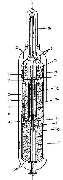
- figure 1 shows schematically a synthesis reactor cartridge
with three catalytic beds with axial-radial flow of the gas
normally adopted when modernizing "in situ" existing
reactors. Most of the stream 1 feed gas enters from the
bottom of the reactor's shell M, runs from bottom to top
along airspace I between the shell and the cartridge C and
goes then to the outside of the exchanger S1 to be pre-heated
by the hot gas leaving from the head of the reactor, stream
5.
The gas so pre-heated stream 1', whose temperature is
controlled b~ a part of the feed gas stream 2, mixes with
stream 4 pre-heated in exchanger S2 and reaches the first
catalytic bed through which it runs with an axial-radial flow
from the inside outwardly, collecting in airspace I' between
cartridge C and the outside wall Pe of the first bed where it
mixes with the fresh quench gas stream 3. The gas so mixed
13~ 1r~j
-- 6 --
to a lower temperature stream 1'' reaches the second
catalytic bed through which it runs reacting and heating up
with an axial-radial flow from the outside towards the inside
of the bed. -The hot gas collects then in air-space I''
formed by the inside wall of the catalytic bed and by the
outer shell of exchanger S2 situated in the central part of
the second catalytic bed and is cooled running from top to
bottom outside the tubes of exchanger S2, finally collecting
at the exchanger's exit to reach the entrance to the third
catalytic bed, stream 1'''.
A stream of fresh gas 4 is fed to the bottom of exchanger
through which it runs inside the tubes pre-heating and
finally joining stream 1'. Stream 1''' finally runs with an
axial-radial flow from the outside to the inside through the
third catalytic bed C3, collecting in the central collector
I''' whence through the cent_al transfer tube T it reached
the inside of the tubes of exchanger S1 where it cools pre-
heating stream 1 finally to leave the converter, stream 5.
- Figure 3 shows the cross-section of a synthesis reactor's
cartridge with three catalytic beds with the gas flowing
radially. Exception made for the flow of the gas in the
beds, which in this instance is radial and not axial-radial
as in Fig. 1, the beds being closed at the top, the gas run
through the various parts of the reactor is as previously
described for Fig. 1.
13l)~
Example
_ _ _ _ _ _ _
With reference to Fig. 1 the following is an exa.~ple of
embodiment of the invention concerning this applicat-sn.
In a synthesis reactor for the production of 1000 MTD of
ammonia the following operating conditions apply:
- pressure at reactor's inlet: 140 bar
Rate of flow Tempera ~re
- stream 1 :7970 Kmol/h 41.0 % 143~
- stream 2 :0 Kmol/h - 143~
- stream 3 :6069 Xmol/h 31.3 % 143~
- stream 4 :5384 Kmol/h 27.7 % 143~
- st-eam 5 :16992 Xmol/h - 352C~
Composition of streamsComposition of st_~am
1, 2, 3, 4 5
___________________________________________
H266.68 % mol H254.68 % r~ci
N222.22 % mol N218.22 % r.oi
CH44.70 % mol CH45.38 % r~l
A4.30 % mol A4.92 % ~.31
NH32.10 % mol NH316.80 % ~.ol
T
13(~
- Figure 4 shows the diagram temperature/reactor's yield
under the operating conditions described above (Fig. 4a) and
the diagrams temperature/state of the art yields described in
Fig. 2 and Fig. 7 of "Nitrogen" (Fig. 4b and Fig. 4c).
As the above-mentioned diagrams show, the improvement in
yield obtained with the reactor described according to the
invention is about 25 to 60% above the yield obtained in the
state of the art.
In the above-mentioned diagrams gas temperature is given in
abscissa and the concentration of ammonia at reactor's outlet
in ordinate.
. . .