Note: Descriptions are shown in the official language in which they were submitted.
~3V~75~
,.
FIELD OF THE INVENTION
, _
1 The present invention relates to a guide o~
support for a soaker hose.
BACKGROUND OF THE INVENTION
Soaker hoses are of a generally flattened
configuration with a series of sprinkling holes ove~ the
upper surface of the hose for a random light water spray
pattern. These hoses are very popular with respect to
home yard use.
There is however one main problem with respect to
soaker hoses. These hoses, typically after having been
rolled up for storage purposes, can be very awkward to lay
down flat or to set at different angles along the length
of the hose without affecting the rest of the hose. These
problems are a direct result of the memory of the hose
material causing the hose to twist along its length and
move to~its own desired position rather than the position
to which it has been set.
SUMMARY OF THE INVENTION
The present invention provides a hose guide
specifically for a soaker hose. The hose guide of the
present invention comprises a gripping portion for
gripping the hose and spike means for ground implant to
support the gripping portion which is used to hold the
hose in a desired set position.
13~7513
SJ-7345-88 - 2 - 5692A/0068A
1 BRIEF DESCRIPTION OF THE DRAWINGS
_
The above as well as other advantages and
features of the present invention will be described in
greater detail according to the preferred embodiments of
the present invention in which;
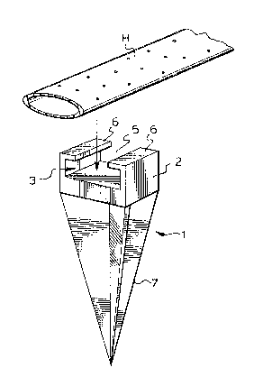
Fiyure 1 is a perspective view of a hose guide
for receiving a soaker hose according to a preferred
embodiment of the present invention.
Figure 2 is a top perspective view of a soaker
hose fitted with a pair of hose guides as shown in Figure
1.
Figure 3 is a sectional view through one of the
hose guides of Figure 2.
Figure ~ is a view similar to Figure 3 showing
the soaker hose set a different spray angle.
DETAILED DESCRIPTION ACCORDING TO THE PREFERRED
EMBODIMENTS OF THE PRESENT INVENTION
Figure 1 shows a soaker hose H. This hose, as can
be seen in the drawings, has a generally flattened shape
with a series of spray holes on its upper surface. The
drawings show the hose as lying down relatively flat.
However, more typically after the hose has been ~olded, it
will tend to twist or bend along its length making it
awkward to set to a desired spray position.
7S~3
SJ-7345 88 - 3 - 5692A/0068A
l Figure l also shows a soaker hose guide,
generally indicated at 1 specifically designed for
gripping and holding the soaker hose in a desired position
with a series of these guides being provided along the
length of the hose as shown in Figure 2 of the drawings.
The soaker hose guide comprises an upper head 2
and a lower spiked body 7. The upper head has a
channel-like construction and specifically includes an
upwardly open channel region 3. The channel region is
undercut to either side through the provision of inwardly
extending lips 6 separated by an open space 5 allowing
access to the channel region.
The lower spike 7 is as seen in Figures l, 3, and
4 of a wedge shape decreasing downwardly in thickness.
The guide is extremely easy yet efficient to
use. The hose, prior to filling with water, is squeezed
down through the opening 5 past lips 6 to effectively lock
in the undercut channel 3. When water is run through the
hose, as shown in Figures 3 and 4, it tends to expand
further enhancing the gripping action of the head portion
on the hose. Furthermore, the hose is able to spray out
past the head portion through the opening between lips 6,
although each individual hose guide covers very little
area on the hose.
After the hose guide has been set up or as will
3û be more usual after a series of the hose guides have been
fitted to the hose7 they are implanted through spike 7
.~3~)~7513
SJ-7345-88 - 4 - 5692A/0068A
1 directly into the ground. The hose, where held by the
guides, will be directed for a spray direction as per the
setting of the guide. In this respect, Figures 2 and 3
show the hose set in a flat position. However, it can
equally as well be set as shown in Figure 4 at different
desired angles according to the implant angle of spike 7.
Also7 various different combinations can be arranged where
one spike is set in the Figure 3 position with the next
spike set in the Figure 4 position ecetera ecetera. The
hose guides will then hold the hose in different desired
spray directions along the length of the hose.
The wedge shaping of spike 7 is particularly
important when considering set ups such as that in Figure
4 where the weight of the hose is easily born by the spike
which again, because of its wedge shaping will not tend to
toppel over from the Figure 4 position.
From the above description it will now be seen
how a very simple hose guide easily fitted to a soaker
hose can efficiently hold that soaker hose for a preset
spray direction rather than having to fight the normal
uncontrolability of the hose.
Although various preferred embodiments of the
invention have been described in detail, it will be
appreciated that variations may be made without departing
from the spririt of the invention or the scope of the
appended claims.
