Note: Descriptions are shown in the official language in which they were submitted.
~31Q791~
OPTICAL FIBER BUN~LE
HAVING IMPROV~D T~RMINAL STRUCTURE
1 Backqround of the Invention
The present invention relates to a terminal structure
of an optical fiber bundle formed by b~lndling a plurality of
optical fibers.
Brief Descriptoin of the Drawings
Fig. 1 is a cross section showing the terminal
construction of the optical fiber bundle according to a
first embodiment of the present invention;
Fig. 2 is a perspective view showing the reflecting
10 mirror member shown in Fig. l;
Fig. 3 is a diagram for explaining a sterilizing method
using the first embodiment of Fig. 1;
Fig. 4 is a diagram for explaining experiments
conducted with the fiber bundle construction of the present
inventiOn;
Fig. 5 is a diagram for explaining the results of the
experiments of Eig. 4;
Fig. 6 is a cross section of an optical fiber bundle
according to a second embodiment of the present invention;
Fiq. 7 is a perspective view showing the reflecting
member shown in Fig. 6; and
Figs. 8 and 9 are diagrams for explaining the prior
art.
It i5 known to introduce light into an optical fiber
25 bundle so as to cause the light to be guided by the optical
fiber bundle to a destination. In this case, light emitted
from a light exit end of the optical fiber bundle has an
exit angle ~ depending on the N.A. (n~lmerical aperture) of
.~
~L3~
1 the optical fiber strands used in the fiber bundle. It is
known that a larger N.A. leads to a larger exit angle ~, and
that the exit angle ~ is determined by the following
expression (1) when the light exits into air:
~ = 2 sin 1 (N.A.~ ........ (1)
The exit angle ~ typically has the following values for
various types of optical fibers:
(1~ In the case of an optical fiber composed of a core
of GeO2 SiO2 and a cladding of SiO2 for use in light
communication or the like, N.A. = 0.3 and therefore ~ = 35.
(2) In the case of an optical fiber composed of a core
of SiO2 and a cladding of SiO2 and fluorine for use in
ultraviolet ray guiding or the like, N.A. = 0.2 and
therefore ~ = 23.
(3) In the case of an op-tical fiber composed of a core
of GeO2 SiO2 and a cladding of SiO2 and fluorine for use
in illumination light guiding or the like, N.A. = 0.35 and
2~ therefore ~ = ~1.
(4) In the case of a multicomponent-glass optical fiber
for use in illumination light guiding or the like, N.A. =
0.55 and therefore ~ = 67.
As described above, an optical fiber of a pure-quartz
core commonly used as a light guide for ultraviolet rays has
tr.e smallest exit anyle ~.
~ eferring to Fig. 8 of the accompanying drawings, the
use of a conventional apparatus will be described hereunder.
Fig. 8 shows a state where the inside of a vessel is
subjected to ultraviolet sterilization by use of a
conventional optical fiber bundle. As illustrated in Fig.
; 8, an optical fiber bundle 1 is disposed so as to be
directed to an opening of a vessel 2, so that ultraviolet
rays emitted from a light exit end surface of the fiber
-- 2 --
.. . .
~, j .
~L3079~1
1 bundle l enter into the vessel 2 as indicated by the
reference numeral 3 in the drawing so as to illuminate the
inner surface of the vessel 2 to thereby sterilize the inner
surface of the vessel 2.
Sterilization by use of the foregoing conventional
apparatus, however, has been subject to the following
problems. A first problem is that, in the case o.f a
bottle-like vessel having a small opening, a lower portion
of the opening indicated by reference n~lmeral 4 in Fig. 8
cannot be sterilized at all. Further, in the case of a
vessel having an uneven inner surface, the uneven portion
often cannot be sterilized because the uneven portion cannot
be irradiated with ultraviolet rays.
A second problem is that, even in the case where an
inner surface of a vessel is irradiated with ultraviolet
rays, the irradiation is performed with a predetermined
angle and therefore sufficient sterilization cannot be
achieved. Fig. 9 is a diagram for explaining this
phenomenon. As illustrated in Fig. g, when the inner
surface of the vessel 2 is irradiated with the ultraviolet
rays 3 from the optical fiber bundle 1 with an inclination
angle of 3/2 (3 being an exit angle), the intensity I of
irradiation is sin(3/2~ times as large as that in the case
where irradiat on is performed vertically. Therefore, in
the case of the foregoing optical fiber composed of a core
of SiO2 and a cladding of SiO2 and fluorine~
sin(Q/2) = sin 11.5
= 0.2
Accordingly, the intensity of irradiation is lowered to
about 20%.
-- 3 --
,~
6~
1 Because the above-described problems, -the
conventional apparatus shown in Fig. 8 has not been used for
sterilization.
It is therefore an object of the present invention
S to provide a terminal structure of an optical fiber bundle
in which it is possible to easily and accurately perform
sterilization of the inside of a vessel such as a bottle or
the like.
Summary of the Invention
According to a first aspect of the present
invention, an optical fiber bundle is provided at its end
with means for reflecting a portion of the emitted light to
the side.
In another aspect, the invention provides an
optical fiber bundle comprising: a ~irst plurality of
optical fibers, their end faces forming a terminal
structure, a second plurality of optical fibers surrounding
said first plurality of optical fibers, reflecting means
surrounding said terminal structure, said reflecting means
radially reflecting light emitted from said second plurality
of fibers and allowing light emitted from said first
~` plurality of fibers to pass without reflection.
In one example, the fiber is provided with a
reflecting member having an opening formed at its central
portion and a circular-cone mirror face formed at its outside
surface, the opening being arranged so that a plurality of the
optical fibers disposed at a central portion of the optical
fiber bundle are inserted into and held by the opening so as to
allow light emitted from the op~ical fibers disposed at the
central portion of the light exit end portion to pass
through the opening. The circular-cone mirror face is
:~;
:
~L3~
,
arranged to reflect light emitted ~rom ~ plurality of the
optical fibers disposed at a circ~lmferelltial portion of the
optical fiber bundle in the direction away from the optical
fiber axis.
According to a second aspect of the present invention
the terminal structure of an optical fiber bundle is
characterized in that a reflecting member is provided which
has an opening formed at its central portion and a
funnel-shaped mirror face formed at a lower inside surface
of the opening, the opening being arranged so that a light
exit end portion of the optical fiber bundle is inserted
into and held by the opening so as to allow light emitted
from a plurality of the optical fibers disposed at a central
portion of the optical bundle fiber to pass through the
opening. The mirror face is arranged to reflect light
emitted from a plurality of ones of the optical fibers
disposed at a circumferential portion of the optical fiber
bundle in the direction intersecting the central axis of the
fiber bundle, the reflection being provided by a funnel-like
mirror face formed on the lower portion inner surface of the
opening of the reflecting member.
Detailed Description of the Preferred Embodiments
Preferred embodiments of the present invention will be
described hereunder with reference to the accompanying
Z5 drawings in which like items are correspondingly referenced.
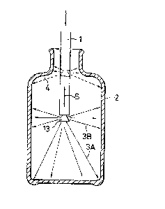
Eig. 1 is a longitudinal cross section showing a
terminal portion of an optical fiber bundle according to a
first embodiment of the present invention. An optical fiber
bundle 1 is concentrically divided into two parts, that is,
30 a central-portion fiber bundle lA and a
circumferential-portion fiber bundle lB which are held by an
inside sleeve 11 and an outside sleeve 12, respectively.
The central-portion fiber bundle lA is projected downward
together with the inside sleeve 11 by a predetermined
35 length, and a reflecting mirror member 13 having a
circular-cone mirror face is fixed to the projecting portion
by an adhesive 14. The adhesive 14 is also interposed
.
.:,,.. , : ... . ;
~3~
1 between the inside sleeve 11 and the circumferential-portion
fiber bundle lB so as to prevent displacement therebetween.
Fig. 2 is a perspective view showing the reflecting
mirror member 13 used in the first embodiment of Fig. 1. As
illustrated in Fig. 2, the reflecting mirror member 13 has
an opening formed at its central port-ion so that the inside
sleeve 11 can be inserted through the opening, and has a
circ~lar-conically finished surface with a predetermined
inclination angle ~ at its circumferential portion. For
example, dielectric multilayer coating or aluminum
evaporation can be performed on the circular-cone surface so
as to make the circular-cone surface a mirror face for
selectively reflecting ultraviolet rays having a wavelength
of about 254 nm.
The operation of the optical bundle fiber according to
the first embodiment will now be described.
Ultraviolet rays propagated through the central-portion
fiber bundle lA are emitted downward from an end surface
thereof as indicated by arrows 3A. Ultraviolet rays
propagated through the circumferential-portion fiber bundle
lB, on the other hand, are emitted from an end surface
thereof, and are reflected by the circular-cone surface of
the reflecting mirror member 13 so as to be directed to the
side as indicated by arrows 3B in the drawing.
Sterilization of a vessel by the first embodiment of
this invention is performed, for example, in a manner as
shown in Fig. 3. That is, the optical fiber bundle 1 is
inserted through an opening of the vessel 2, and is then
reciprocated in the direction of an arrow S. The downward
emitted ultraviolet rays 3A irradiated a bottom sur~ace of
; the vessel 2, and the deflected ultraviolet rays 3B
irradiate a side surface of the vessel 2. As a result, a
-- 6 --
.
- .
- ~3~37~6~
1 lower portion 4 of the opening of the vessel 2 is equally
irradiated with the ultraviolet rays to thereby be
sterilized. Even if the vessel 2 has an uneven inner
surface, the inner surface can be efficiently irradiated
with ultraviolet rays.
Various modifications of the foregoing first embodiment
can be made. For example, although in the foregoing
embodiment the inside sleeve 11 holds the central-portion
fiber bundle lA and the reflecting mirror member 13 having
the circular-cone face is fixed to the sleeve 11, the
reflecting mirror member 13 may instead be directly fixed to
the central-portion fiber bundle lA. Further, it is not
always necessary to use the adhesive, and it is not always
necessary to make the axial position of the end surface of
the central-portion fiber bundle lA coincide with the lower
end of the reflecting mirror member 13.
The inclination angle n of the circular-cone surface
may be selected, for example, to be 45~ so that horizontal
reflection can be performed. If a < 45, on the other hand,
the reflected light can be sent upward, so that
sterilization of the lower portion of the opening of the
bottle can be more accurately performed.
The ratio of the number of strands constituting the
central-portion fiber bundle lA to the number of strands
constituting the circumferential-portion fiber bundle may be
selected in accordance with a shape of the vessel, an object
of use, and so on. Further, the ratio may be changed in
accordance with the speed of a line usillg the optical fiber
bundle.
39 Various materials can be used for the elements
according to the present invention. For example, the
material for the adhesive 14 may be an ordinary epo~y group
1;~07~
l resin, although it is`not limitad to this. Further, the
method of finishing the reflecting surface is not limited to
a dielectric multilayer film coating or the like, and the
ultraviolet rays to be used are not limited to those having
a wavelength of 254 nm.
In order to confirm the effectiveness of the foregoing
embodiment, experiments were performed by the inventor of
this application as follows.
First, a fiber bundle 1 having an effective bundle area
of about 900 optical fiber strands was prepared, with each
of a central-portion fiber bundle lA and a
circumferential-portion fiber bundle lB constituted by about
450 optical fiber strands. A reflecting mirror member 13
was attached as shown in Fig. l, and the angle a in the
drawing was selected to be 45. The outer diameter of a
circular-cone mirror face was selected to be about 8 mm and
the reflection factor of the mirror face was selected to be
90%. As a prior art example, on the other hand, an optical
bundle fiber having an effective bundle area of about 900
optical fiber strands was prepared and used without
modification.
A vessel such as shown in Figs. 4(A) and 4~B) was used
as an object to be sterilized, the vessel comprising a pipe
41 having an inner diameter of 50 mm and a height of 100 mm.
Ultraviolet rays having a wavelength of 254 nm were supplied
through each of the optical fiber bundles 1 and 31 with an
intensity such that an intensity value measured at a
position 1 cm away from a light exit end of the optical
bundle fiber was 700 mW/cm2, and the optical fiber bundle
was operated as shown by arrows S1 through S5 in the
diagrams of Figs. 4(A) and 4~B).
-- 8
- ~3~)796~
1 In the foregoing experiments, the intensity of
ultraviolet irradiation was measured on an inner side
surface of each of the pipes 41, and Fig. 5 illustrates the
measurement results obtained. As seen in Figure 5, the
intensity of irradiation according to the embodiment of the
present invention along the side surfaces of the pipe was
about five times as much as that in the prior art example.
A second embodiment of the present invention will now
be described with reference to Figs. 6 a~d 7.-
Fig. 6 is a cross section showing the second
embodiment, and Fig. 7 is a perspective view showing a
reflecting member to be used in the same embodiment. The
second embodiment is different from the first embodiment in
that a reflecting member 21 is attached to an outside sleeve
12 and that an inwardly tapered reflecting surface is formedat a lower inner surface portion of an opening of the
reflecting member 21.
According to thi~ embodiment, light emitted from the
optical fibers disposed at a circumferential portion of the
optical fiber bundle 1 is reflected by the funnel-like
surface of the reflecting member 21. Therefore, ultraviolet
rays can be sent sidewards as shown by arrows 3B in Fig. 6.
Further, in this second embodiment, it is not necessary
to divide the optical fibers constituting the optical fiber
bundle 1 into central and circumferential pvrtions in
advance, and it is not necessary to specifically modify the
shape of the terminal end of the conventional optical fiber
bundle. Therefore, not only can the design and fabrication
of the terminal be easily performed but also the reflecting
member 21 can be exchanged with different reflecting members
in accordance with the shape of the vessel.
~L3~
1 As described in detail above, according to the first
aspect of the present invention, light from the
circumferential-portion fiber bundle is reflected sidewards
by the circular-cone mirror face formed on the outer surface
of the reflecting member, so that sterilization at the
inside of the inside of a vessel such as a bottle or the
like can be easily and accurately performed.
According to the second aspect of the present
invention, light from the circumferential portion of the
optical bundle fiber is reflected sidewards by the
: funnel-like mirror face formed on the lower inner surface
portion of the opening of the réflecting member, so that
sterilization at the inside of a vessel such as a bottle or
the like can again be easily and accurately performecl.
Further, according to this second aspect of the present
invention, there is also the advantage, that the reflecting
memb~r can be easily exchanged in accordance with a desired
irradiation pattern characteristic of a particular object of
use.
- 10 -