Language selection

Search

Patent 1308539 Summary

Third-party information liability

Some of the information on this Web page has been provided by external sources. The Government of Canada is not responsible for the accuracy, reliability or currency of the information supplied by external sources. Users wishing to rely upon this information should consult directly with the source of the information. Content provided by external sources is not subject to official languages, privacy and accessibility requirements.

Claims and Abstract availability

Any discrepancies in the text and image of the Claims and Abstract are due to differing posting times. Text of the Claims and Abstract are posted:

  • At the time the application is open to public inspection;
  • At the time of issue of the patent (grant).
(12) Patent: (11) CA 1308539
(21) Application Number: 1308539
(54) English Title: PULL TAB FOR SLIDE FASTENER SLIDER
(54) French Title: TIRETTE POUR FERMETURE A GLISSIERE
Status: Term Expired - Post Grant
Bibliographic Data
(51) International Patent Classification (IPC):
  • A44B 19/26 (2006.01)
(72) Inventors :
  • ISHII, SUSUMU (Japan)
(73) Owners :
  • YKK CORPORATION
(71) Applicants :
  • YKK CORPORATION (Japan)
(74) Agent: GOWLING WLG (CANADA) LLP
(74) Associate agent:
(45) Issued: 1992-10-13
(22) Filed Date: 1988-03-30
Availability of licence: N/A
Dedicated to the Public: N/A
(25) Language of filing: English

Patent Cooperation Treaty (PCT): No

(30) Application Priority Data:
Application No. Country/Territory Date
62-54658 (Japan) 1987-04-13

Abstracts

English Abstract


ABSTRACT OF THE DISCLOSURE
A pull tab for a slide fastener slider is disclosed
which comprises a first member made of a hard, rigid
material and pivotally connected to the slider and a second
member made of a soft, resilient material engageable
through a plug and socket connection with the first member.
The pull tab can be manipulated with utmost ease and
security to the user.


Claims

Note: Claims are shown in the official language in which they were submitted.

WHAT IS CLAIMED IS:
1. A pull tab for a slide fastener slider which
comprises a first member made of a metal or hard plastics
material and pivotally connected to the slider and a second
member made of a soft, resilient material, said first
member having a socket and said second member having a plug
engageable with said socket, said socket having a cross-
sectionally generally U-shaped transverse cavity with one
end open and the other end closed adapted to receive a
complementarily shaped plug.
2. A pull tab according to claim 1 wherein said plug
has a saw-toothed surface.
3. A pull tab according to claim 1 wherein said
socket and said plug are provided with tapered portions for
mutual abutment and with an aperture and a protuberance,
respectively.
4. A pull tab according to claim 1 wherein said
socket has a projection adapted to be clamped over said
plug.
5. A pull tab according to claim 1 wherein said
socket has a notch engageable with a recess in said plug.
6. A pull tab according to claim 1 wherein said
first member has a pair of identical sockets interconnected
by a second member having two identical plugs.
- 6 -

Description

Note: Descriptions are shown in the official language in which they were submitted.


1 3~)~539
BACKGROUND OF THE INVENTIt)N
1. Field of the Invention:
This invention relates to a slider for a ~liding
clasp fastener and more particularly to a slider pull tab.
2. Description of the Prior Art:
Numerous forms of slide fastener sliders have been
proposed in the art, some of which were equipped with pull
tabs of a slip-free design. One such slider is disclosed
in Japanese Laid-Open Utility Model Publication No.
60-60912 in which the slider pull tab is made of metal,
hard plastic or other hard and stiff material and has a
coarsely surfaced, slip-resistant member engaged in an
opening at its tip end. While this prior art slider is
satisfactory in that it can be positively moved with
fingers which are prevented from slipping off from the pull
tab, it has a drawback in that since its pull tab is hard
and rigid, the finger pressure applied to pull is apt to
deflect vertically and impose undue stresses on the slider
body, and a further drawback in that being integral with
the slider body, the pull tab when erected tends to injure
the wearer and it is difficult to make available dlfferent
forms of pull tabs tailored to meet with versatile
customers' needs.
SUMMARY OF THE INVENTION
It is therefore the primary object of the present
invention to provide a slider for a sliding clasp ~a~tener
which is equipped with such a pull tab which can be

- 1 30~53q
manipulated smoothly without undue stresses on the fingers
of the user, which is free from physical injury upon the
user, and which is capable of meeting with a versatility of
customer needs.
In general terms, the invention provides a pull tab
f~or a slide fastener slider which comprises a first member
made of a metal or hard plastics material and pivotally
connected to the slider and a second member made of a soft
resilient material, said first member having a socket and said
second member having a plug engageable with said socket, said
socket having a cross-sectionally generally U-shaped transverse
cavity with one end open and the other end closed adapted to
receive a complementarily shaped plug.
The above and other object and features of the
invention will be better understood from the following
description taken in connection with the accompanying
drawings which illustrate by way of example some preferred
embodiments of the invention and in which like reference
numerals refer to like or corresponding parts throughout
the several views.
BRIEF DESCRIPTION OF THE DRAWINGS
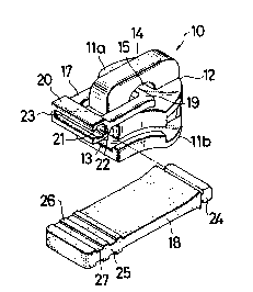
FIG. 1 is a perspective view of a slider embodying
the invention;
FIG. 2 is a plan view of the slider shown assembled
with its pull tab;

1 3r)8539
FIG. 3 is cross-~ectional view taken on the line
III-III of FIG. 2;
FIG. 4 is a perspective view of a portion of a
modified form of pull tab;
FIG~ 5 is a cross-sectional view of a portion of
another modified fonm of pull tab: and
FIG. 6 - 9, inclusive, each are perspective views of
further different forms of pull tabs according to the
invention.
DETAILED DESCRIPTION OF T~E INVENTION
Referring now to the drawings and FIG. 1 in
- 2a -

~ 3n~539
particular, there is shown a slider lO which comprises a
slider body 11 including upper and lower wings lla, llb
joined at their front end by a neck 12 so as to define a
generally ~-shaped guide channel 13 for the passage of
slide fastener stringers not shown. Designated at 14 is a
support lug secured to the upper surface of the upper wing
lla and provided centrally with an aperture 15 for
receiving one end of a pull tab hereafter described.
The pull tab designated at 16, which constitutes an
important aspect of the invention, comprises a first member
17 made of a metal or hard plastics material and a second
member 18 made of a soft, resilient material such as soft
rubber, soft vinylchloride resin, soft polyurethane resin
or the like. The first member 17 serves as a link
connecting the second member 18 to the slider body ll, for
which purpose it has a spindle l9 at the front end
pivotally connected through the aperture 15 to the support
lug 14. At the rear end of the first member 17, there is a
socket 20 which has a cross-sectionally U-shaped transverse
cavity 21 with one end open as at 22 and the other end 23
closed.
The second member 18 generally rectangular in shape
has a plug 24 at one or front end which is formed
complimentarily to and engageable through the U-shaped
cavity 21 with the first member 17. At and adjacent to the
other or rear end of the second member 18, there is
provided a gripping ~one 25 defined by alternate ridges 26

1 ~n~s3q
and grooves 27 which is adapted to be gripped with fingers,
which can be done without slipping, to effect a sliding
movement of the slider 10 along the fastener stringers.
The slider 10 of FIG . 1 is shown in FIG . 2 as
assembled by inserting the plug 24 into the cavity 21 and
the joint of the first and second member 17, 18 is better
shown in FIG. 3, which is firm enough to prohibit the
second member 18, should this be twisted, against
detachment from the first member 17.
The second member 18 shown in FIG. 4 has a somewhat
different plug 24 which is provided with a saw-toothed
surface 24' thereby enhancing its coupling strength.
FIG. 5 shows a somewhat sophisticated form of the
joint between the first member 17 and the second member 18
in which the socket 20 and the plug 24 are provided with
tapered abutments 20a and 24a, respectively and further
with an aperture 20b and a protuberance 24b, respectively,
the arrangement being that the plug 24 can be anchored
stably in place within the socket 20.
A pull tab 16 shown in FIG. 6 is the same as that
shown in FIG. 1 except that the socket 20 is provided at
its open end 22 with a projection 28 adapted to be clamped
over the plug 24, when the latter is inserted, so as to
prevent the same from displacement.
FIG. 7 shows a modification in which the socket 20
has a notch 29 adapted to be urged into a recess 30 in the
plug 24 so as to hold the two pull tab members firmly

1 ;~0~539
together.
A modification of pull tab 16 shown in FIG. 8 has an
elongated first member 17 and a shortened second member 18,
the latter having inwardly curved surfaces to provide a
gripping portion 31.
A modif ication shown in FIG. 9 is characterized by
the provision of a pair of first members 17, 17 having
identical sockets 20, 20 and a second member 18 having two
identical plugs 24, 24 engageable with the respective
sockets 20, 20.
Although various minor modifications may be suggested
by those versed in the art, it should be understood that I
wish to embody within the scope of the patent warranted
hereon, all such embodiments as reasonably and properly
come within the scope of my contribution to the art.

Representative Drawing
A single figure which represents the drawing illustrating the invention.
Administrative Status

2024-08-01:As part of the Next Generation Patents (NGP) transition, the Canadian Patents Database (CPD) now contains a more detailed Event History, which replicates the Event Log of our new back-office solution.

Please note that "Inactive:" events refers to events no longer in use in our new back-office solution.

For a clearer understanding of the status of the application/patent presented on this page, the site Disclaimer , as well as the definitions for Patent , Event History , Maintenance Fee  and Payment History  should be consulted.

Event History

Description Date
Inactive: Expired (old Act Patent) latest possible expiry date 2009-10-13
Grant by Issuance 1992-10-13

Abandonment History

There is no abandonment history.

Owners on Record

Note: Records showing the ownership history in alphabetical order.

Current Owners on Record
YKK CORPORATION
Past Owners on Record
SUSUMU ISHII
Past Owners that do not appear in the "Owners on Record" listing will appear in other documentation within the application.
Documents

To view selected files, please enter reCAPTCHA code :


To view images, click a link in the Document Description column. To download the documents, select one or more checkboxes in the first column and then click the "Download Selected in PDF format (Zip Archive)" or the "Download Selected as Single PDF" button.

List of published and non-published patent-specific documents on the CPD .

If you have any difficulty accessing content, you can call the Client Service Centre at 1-866-997-1936 or send them an e-mail at CIPO Client Service Centre.


Document
Description 
Date
(yyyy-mm-dd) 
Number of pages   Size of Image (KB) 
Cover Page 1993-11-04 1 10
Abstract 1993-11-04 1 9
Claims 1993-11-04 1 24
Drawings 1993-11-04 4 56
Descriptions 1993-11-04 6 141
Representative drawing 2000-08-09 1 11
Fees 1995-09-06 1 85
Fees 1996-09-16 1 82
Fees 1994-08-24 1 90