Note: Descriptions are shown in the official language in which they were submitted.
I 3l,~625
G-1,167
SOLE~pID VALV~ ASSEMBLY
The invention relates to a valve as~embly
having normally opened and normally closed valve~
controlled by solenoid3 to pro~id~ various connected
and disconnected arrangement~ in a fluid system. It is
particularly useful in a wheel lock control or
anti-skid brake system (ABS).
The two solenoid control valves are preferably
placed in a 3ingle package and arranged in geometric
series connec-tion. The valve assembly preferably has
four functional modes with three fluid ports. The four
functional modes are controlled by energizing or
deenergizing the solenoids in various combinations.
When used in an ABS system, there is a pressure input
port, a pressure output port, and a pressure release
port or exhaust port which releases fluid directly to a
reservoir. The fluid connection hetween the input port
and the output port~ an~ the fluid connection between
the output port and the pres~ure release po~t, are
within the valve assembly. The assembly preferably has
a common chamber made of t~o ~hin-walled stainless
steel tubes and a center channeled plungex stop to
which the two tubes are attached at each end thereof.
The channel arrangement provides the shortest fluid
passag~ from the pressure output port ~o the pressure
release port within the valve assembly while having a
minimum fluid energy loss.
~'~.t~ ` t '~
1 3~625
It is another eature of the invention that
the electrical connection and the direction of the coil
windings of the two solenoids assist in foxming a
continuous enhancible magnetic flux p~ttern so that th2
resulting magnetic fields can provide enhanced
perform~nce.
I~ is a feature of the invention that the
center thin-wall stainlesq steel tubes act as cham~ers
which contain the valve plungers, which are also
solenoid armatures, with pres~urized fluid being within
the tubes under certain conditions. The arrangement
avoids axial loading against the thin wall tubes and
the tubes are strengthened so as to contain the fluid
pressure therein by the position of the solenoid coils
and coil housings immediately about^each tube.
It is another feature of the invention to
provide a triple cascade orifice configuration to
fu~ction effectively and quietly in high pre~sure
application. The triple ca cade orifice is
: 20 positioned between the prescure input port and the
pressure output port and includes ~hree orifices
provided in series, the third orifice being established
by the opening between a ball valve and the cylindrical
wall in which the ball valve is located when the ball
. 2
1 3C3625
is unseaked so as to permit flow therepast. This
arrangement pro~ides sufficient fluid flow at high
compressed fluid pressures with the least pressure
differential acro~s each of the individual orifices,
tending to eliminate fluid cavitation and to alleviate
induced noise resulting therefrom.
IN THE DRAWING:
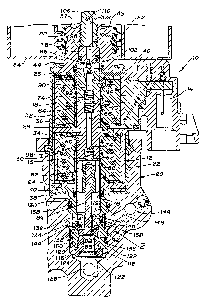
Figure 1 is a cros6-section view with parts
broken away showing the solenoid valve assembly
embodying the invention.
Figure 2 is an enlarged fragmentary portion of
Figure 1 as indicated by circle 2 on Figure l.
The solenoid valve assembly lO is illustrated
as having a housing section 12 which includes the
electrical connector 14. It also houses the two
solenoid assemblies 16 and 18 as well as at least
portions of the val~es and fluid passages controlled
thereby. Assembly 10 also includes a housing section
20 which houses a portion of the solenoid assembly lB
as well as the normally open valve controlled by that
solenoid. The two solenoids are illustrated as being
contained within a solenoid cas~ assembly 22. The
solenoid assemblies 16 and 18 are also associated with
end plates 24 and ~.6, respectively, as well as the
center or plunger stop support plate 28. Solenoid cvil
frames 30 and 32, respectively containing solenoid
assemblies 16 and 18, engage the plates 24, 26 and 28
and cooperate there~ith to bear the axial load in
compressive loading condition~ so that the axial load
is not carried through the solenvid coil 34 of solenoid
assembly 16 or the solenoid coil 36 of solenoid
as~embly 18. Solenoid assembly 16 has one end 38 of
1 3 ,', ~!3 6 ~ 5
case assembly 32 crimped over a flan~e 40 of the
normally open valve housing 42. The other end 44 of
case assembly ~2 is similaxly crimped about a flange 46
of the solenoid assembly cap 48. Cap 48 is illustrated
as being provided with a mul~iple land sealing grommet
50 which extend~ through a tube-like boktom portion 52
of the reservoir 54 so that the upper end 56 of cap 48
opens into the reservoir 54 and tha grommet 50
effectively seals between the cap 48 and the reservoir
portion 52. Res~rvoir 54 is preferably ~he reservoir
for the master cylinder and the boost~r of the brake
system, as well as for the ABS system of which the
solenoid valve a~sembly h~rein disclosed and claimed is
preferably a part.
The plunger stop assembly 58 includes the stop
60 and the stainless steel tubes 62 and 64. Stop 60
has a through passage or channel 6~ formed axially
therethrough and having slightly enlarged passage ends
68 and 70. A spring 72 is positioned in passage end 68
and abuts the shoulder formed at the bottom portion
thereof. Another spring 74 is similarly positioned in
passage end 70. The center portion of plunger stop 60
is suitably slotted or grooved so as to receive at
least a part of plate 28 therein to anchor and locate
the plunger Ytop a~sembly 58 axially and radially. The
out~r end 76 of tube 62 extends into the valve housing
42, and the outer end 78 of tube 64 extends into the
solenoid as~embly cap 48. The cylindrical spaces
outwardly of the plunger stop and the ends 76 and 78 of
the stainless steel tubes provide cylinders. The inner
ends of the stainless steel tubes are secured to the
.~ :
'1 30~1~25
plunger stop 60 in any suitable manner, for example by
welding. The electrical connector 14 has suitable
terminals and connecting wires arranged for
energization and deensrgization of each of the solenoid
coils 34 and 36. These coils are wound in opposite
directions for reasons to be described. Solenoid
assembly 16 has a solenoid armature or plunger 78 which
is reciprocably received within tube 62 and ha axially
extending pas~aqes 80 which permit fluid flow
therepast. Spring 68 is in engagement with the inner
end 82 of plunger 7~ so as to urge that plunger
outwardly of the tube 62. A rod 84 has one end secured
to plunger 78, with the other end extending outward of
tube 62 and into a portion of the valve housing 42.
Rod 84 is provided with a head 86 which controls the
condition of the normally open valve 88, described in
greater detail below.
Solenoid asse~bly 18 has an arma~ure or
plunger 90 reciprocably received for axial movement in
tube 64. Spring 7~ engages plunger 90 and urges that
: plunger outwardly of tube 64. Plunger 90 also has a
passageway 92 formed therethrough which is in
: continuous fluid communication with passage or channel
66 of the plunger stop 60. Plunger 90 and passage 92
are formed to provide a valve head 94 which is a part
of the normally closed valve 96~ A ~eat member 98 is
sealingly mounted in the outer end 78 of tube 64 and
has a restrictive orifice passageway 100 formed
therethrough. The end of passageway 100 facing valve
head 94 is formed as a valve seat 102, and valve head
94 is normally in engagement with valve seat 102 to
maintain passageway 100 closed. The seat member 98 is
1 ~'J36~5
provided with a seal 104 which preve~ts leakage betwe~n
the seat member and the inner wall of tube 64. ~he
other end of seat member 98 is engaged by the inner end
of a plug 106 which is threaded into cap 48 so as to
provide the appropriate axial position of seat member
98. Plug 106 has a recess 108 formed therethrough in
continuous fluid communication with passageway 100.
The upper end of recess 108 is provided with a port 110
which is the release port of the assembly. Port 110
opens into the interior of reservoir 54. It can be
readily seen that any fluid passing through passageway
100 and recess 108 will then be discharged directly
into the reservoir.
Valve housing 42 has a center wall 112
provided with a passageway 114 extending axially
therethrough. Rod 84 extends through this passageway
but is somewhat smaller in diamet~r than the diameter
of the passageway so that fluid communication is
maintained between the interior of tube 62 and the
other side of the center wall 112. On the other side
of wall 112 is located the rod head 86 which is axially
spaced slightly from that wall. A plug 116 is inserted
in the outer opening 118 of valv0 housing 42 and limits
axially outward movement of the valve head 86. Plug
116 has a passage 120 extending axially therethrough,
with a filter 122 held in the outer end of passage 120
by a retainer 124. Thus passage 120 is connected
through the filter 122 to the pressure output port 126
provided in a part of housing section 20 in which the
valve housing 42 and the plug 116 are mounted.
The valve housing center wall 112 is of a
decreased diameter in relation to the housing ends 128
'I 3[)1(3~25
and 130 so that an annular chamber 132 is formed
thereabout, this chamber being defined on its outer
circumference by a portion of the cylinder wall 134 of
the cylinder-like recess in housing section 20 into
which the valve housing 42 is mounted. Suitable seals
136 and 138 are respectively provided on valve housing
ends 128 and 130 50 as to seal the annular chamber 132
relative to the pressure outlet port 126 and the
portion of housing 20 containing a part of the solenoid
assembly 16.
As shown more clearly in Figure 2, a L-shaped
passage 136 is formed in the valve housing center wall
112 with one end 138 opening into the annular chamber
132 through a first orifice 140 formed in orifice plate
142. Plate 142 i~ mounted in the end 138 of passage
136. An annular filter 144 is secured in the annular
chamber 132 so that all fluid flowing from the chamber
into passage 136 first passes through that fil$er. It
is noted tha annular chamber 132 is in continuous
fluid communication with a passage 146 in housing
section 20 which is directly connected to the pressure
input port 148. Thus operating pressure is supplied to
the valve assembly via pressure input port 148 and is
always contained in the annular chamber 132. Passage
136 has another portion thereof formed to provide as
second orifice 150 which extends parallel to the axis
of the valve housing 42 and opens to provide a valve
seat 152 and a valve cylindrical wall 154, which in
turn is fluid connected to the passage 120 and outlet
port 126 through filter 122. The normally open ball
check valve 88 is positioned within cylindrical wall
154 so as to be engageable with valve seat 152. When
.
1 3n~625
the rod head 86 is positioned downwardly as seen in
Figure 1, solenoid coil 34 being deenergized, the head
is sufficiently spaced fr~m the center wall 112 to
permit the ball check valve 88 to be spaced from its
seat 152 and therefore to permit flow through the
passage 136 including orifices 140 and 150. A third
orifice 156 is defined by the annular space around the
ball check valve 88 and the surface of cylindrical wall
154. When the solenoid coil 34 is electrically
energized, it acts on plunger 78 to move the rod 84 and
its head 86 upwardly as seen in Figure 1 to force valve
88 into engagement 88 with its valve seat, holding the
valve closed.
Another ~-shaped passage 158 in the ~alve
.~ 15 housing center wall 112 connects the annular chamber
132 with the output port 126 at all times. Ball check
valve 160 prevents reverse 10w from the annular
chamber 132 to the output port 126. A portion of
passage 158 adjacent the valve seat of check ~alve 160
is an orifice which will permit flow from the pressllre
ou~put port 126 to the pressure input port when ~he
pressure output port 126 is trying to be at a greater
value than that of the input por~. Thus valve 160 and
passage 158 prevent the output pressure 126 from being
greater at any time than that of the pressure at input
port 148.
The three orifices 140, 150 and 156 between
the input put 148 and the output port 126 provide a
triple cascade orifice configuration which functions
effectively and quietly in high pressure applications.
At the same time it permits a sufficiently high fluid
flow at high compressed fluid pressures with the least
: 8
,
I 3G~6~)5
pressure differential across each individual oxifice,
hence minimizing fluid cavi~ation and alleviating noise
induced from such cavitation.
The normal, deenergiæed, position of the
valves in the assemblies is the position for normal
pressure apply from the pressure input port 148 to the
pressure output 126 through the normally opened valve
88. This occurs when both solenoid coils 34 and 36 are
deenergized so that valve 88 is opened and valve 96 is
closed. Input pressure will also be conducted through
the passageway 114 and past plunger 78, into passage 66
and passageway 92. However, the normally closed valve
96 prevents it from being conduc~ed to th0 reservoir 54
through port 110.
In the output pressure hold mode the solenoid
coil 34 controlling the normally open valve 88 is
energizedl moving plunger 78 toward plunger stop 60,
and moving rod head 86 50 that it engages the ball
valve 88 and moves that valve, holding tha~ valve
seated against its valve ~eat 152. ~his thereore
closes off the input pressure in port 148, and holds
the output port pressure in port 126 to the pressure
therein at the time valve 88 was closed. Since valve
96 remains closed, the pressure in the output port 126
neither decreases nor increases.
When the pressure in the output port is to be
released to a lesser pressure, or even to zero
pressure, the solenoid coils 34 and 36 are both
energized, closing or keeping valve 88 closed as in the
previous state, and moving plunger 90 toward the
plunger stop S0 to open valve 96. The output port
pressure is then connected through passage 126 and
1 3(~'3625
passage way 114 as well as passage 66 and passageway 92
to the r~strictiv~ orifice passage 100 which controls
its ra~e of flo~, after which it enters the reservoir
54 through the release port 110. The pressure apply
mode may be reinstituted by deenergizing both solenoid
coils, returning the valves to their re~pective
normally open and normally closed positions.
When there is trapped air in the system a
trapped air bleed mode is established by deenergizing
coil 34 if it is energized, and energizing coil 36.
This opens both valves 88 and 96, allowing the system
to be bled, with the flow of pressure from the input
port assisting in flushing any trapped air out of the
assembly. Once the assembly is bled, both solenoids
are then normally deenergized to return the assembly so
that it may again permit the the application of
pressure from input port 148 to output port 126.