Note: Descriptions are shown in the official language in which they were submitted.
~ 30865~
IMPROVEMENTS IN CAPSULES
This invention relates to capsules of the sort com-
prising a generally cylindrical body portion and a cap portion
adapted to fit telescopically onto the body portion, and in
particular to hard gelatin capsules of the sort commonly
employed to contai~ pharmaceutical preparations.
~ard gelatin capsules are made in two parts by dip-
ping steel pins into a molten gelatin solution, allowing thegelatin to set and dry, and stripping the shells so for~ed
off the pins.
It is generally known that the gelatin film, as it
dries, also undergoes shrinkage. Control of hu~idity during
and after the drying process is critical to the dimensional
stability of the formed capsules. The shrinkage depends on
a number of factors such as the amount of water to be elimina-
ted, the type of gelatin used, the drying r~gime and the
number and type of additives such as dyes or surfactants.
The capsules undergo a further loss of up to 3% moisture
after being stripped from the pins on which they are formed.
The effect of variations in the drying conditions
and gelatin composition lead to variations in the diameters
of the formed and dried shells. In addition, the effect of
gelatin flow in the dip pan on the film formation, together
with the co~ici~y of the pin and the presence of profiles
which may be present, such as those provided to allow locking
,
-2~ 1 30~65~
of the capsule halves on assembly, combine with ~he dr~ing
system to cause the cross-section of the dried capsule to
depart from circularity, thus producing an oval mouth.
One effect of this ovality is to produce difficulties
in assembling the two halves of the capsule. Instead of
telescopically en8aging each other, the ~wo halves may come
into abutmen~, with possible splitting of one or both halves
of the capsule with immediate or subsequent loss o the
capsule contents.
Attempts have been made to overcome ~he problems of
ovality, for exam~ple by modi~ying the design. However,
until now it has not proved possible to find a satisfactory
solution to the problem, and measurements carried out on size
1 capsule caps of nominal diameter 6.9 mm have shown that the
ovality, as detenmined by measuring the difference between
the larges~ and the smallest diameters, is as high as 0.3 mm,
whatever the manufac~uring source of ~he capsule is.
The present invention provides a solution ~o the
ovality problem, without requiring a modification of the
capsule forming and drying conditions.
This invention provides a capsule shell having an
annular groove in the region of the open end. The groove is
preferably in the capsule CaP.
According to the present invention, therefore, there
is provided a capsule shell of the sort comn~nly ~mployed to
contain pharmaceutical preparations selected from a
generally cyllndrical capsule body portion, or a capsule
cap portion which is adapted to fit telescopically onto the capsule bcdy
~ !
.~.
" ~2b- 1 30865~
portion, wherein the said capsule body or cap portion contai~s
an annular groove o from about O.Ol mm to about 0.05 mm deep in
the region of the open end to reduce ovality in the open end
of the capsule ~ody or cap portion.
By "in the region of the open end" i8 meaRt spaced
at a short distanoe fro~ the open end, i.e. ~o more than 2mm
and preferably between abou$ 0.5 mm and abou~ 1.5 mm from the
cut edge, dependi~g ou the capsule size.
~ 3_ l 308S5~
The presence of the annular groove allows the
capsule film to be dried under the usual conditions with a
greatly reduced tend~ncy to become oval. In a si~e l
capsule~ for e~ample, the groove may preferably be positioned
at a distance of from about 0.5 m~ to about 1.6 mm from the
open end of the shell. The groove is preferably continuous.
However, it is possible to achieve the advantages of the
decreased ovality using a segmented groove having, for example,
from about 2 to about 12 segments. The segments should pref-
erably encircle at least about 90% of the circumference ofthe shell. Typically, the width of the groove is from about
0.3 mm to about 1.5 mm, with a depth of from about 0.01 mm to
about 0.05 mm.
The diMensions, cross-sectional profile and position
of the groove are not critical. The preferred dimensions
will depend on the size of the capsule. Thus for the common
capsule sizes the parameters may typically be selected from
those shown in the following table.
20 Capsule GrooveDistance from Groove
Size Depth (mm)Cut Edge (mm)* Width (mm)
00 0.025-0.0351-1.6 0.51-0.55
0 0.025-0.0351-1.6 0.51 0.55
1 0.020-0.0301-1.6 0.46-0.50
2 0.015-0.0250.8-1.4 0.37-0.41
3 0.010-0.0200.7-1.3 0.32-0.36
4 0.010-0.0200.7-1.3 0.32-0.36
* Measured to the centre of the groove.
~`` 4 l 30~65~
The cross-sec~ion of the groove may have a profile
which is curved or angular, and may range iQ shap~, for
example, from a single to a multiple radius design, or from a
V shape to a multiangular shape, such as for example a
square, rectangular or trapezoidal shape.
The invention will be more readily understood by
reference to the accompanying drawing, in which figure 1
shows a non-limiting example of a capsule cap manufactured in
accordance with the invention, while figure 2 shows in
enlarged form representative configurations of the detail
circled at A in figure 1.
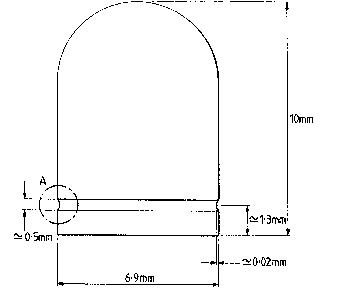
Figure 1 represents the cap portion of a size 1
capsule. The overall length of the si7e 1 capsule cap is
10 mm. A groove of depth 0.02 mm aud width 0.50 ~m is
lS formed with its ce~re at a distance of 1.3 mm rom the cut
edge. The cap is formed on a pin having a corresponding
proile.
The cross-sectional shape of the groovP may have
any convenient shape, and figure 2 indicates a non-exhaus~ive
selection of suitable groove cross-sectional shapes which may
be used.
The capsule shells of the invention may also
incorporate other formations, such as, for e~ample, locking
formations as described in British Patents 970761, 1040859
and 1442121.
~ 5 ~ 1 308654
In another aspect, the invention also comprises a capsnle-
forming shell of the inv~ntion, the pin being configured such as to
m3ke a capsule shell of the sort commonly employed to contain pharma-
ceutical preparations selected from a generally cylindrical capsule
body portion, or a capsule cap portion which is adapted to fit tele-
scopically onto the capsule bcdy portion, wherein the said capsule body
or cap portion contains an annular groo~e of from about 0.01 mm to
about 0.05 mm deep m the region of the open end to reduce ovality in
the capsule bcdy or cap portion.
A series of trials was carried out to produce gelatin caps
of different designs, containing either 2 "PRE-LOK" (registered Trade
Mark) formations or 4 "PRE-LOK" formations (see British Patent No.
1,442,121). The caps were produced with a 0~02 mm groove as shown m
Figure 2.
Test 1
Size 1 capsule caps were produred having 2 PRE-LOK
l formations and an annular groove as described above. Simul-
taneously were produced standard size 1 capsule caps having 4
1 PRE-~OK formations but with no annular groove. A sample of
! 50 caps of each sort was taken when the relative humidity was
15%. The ovality of each cap was determined by measuring
its maximum and mi~imum diame~ers in mm and taking th~
difference. ~or the standard caps the average ovality was
0.127 mm, while for the capsules having the circular groove
the average ovality was reduced to 0.089 mm.
Test 2
The above test was repeated on a separate occasion
and samples taken when the relative humidity was 14.5%. The
standard capsules showed an average ovality of 0.132 ~m while
~he capsules having the a~nular groove showed an average
ovality of only 0.079 mm.
'i~ 1
,~,............................. .
`-`` I 30865~
Test 3
Size 1 capsule caps were produced having 2 PRE-~OK
formations and an annular groove as in Test 1. Simultan-
eously were pr~duced standard size 1 capsule caps having 2
PRE-LOK formations and also having the POSILO~ (registered
Trade Mark) formation desGribed Ln ~ritiah Patent No. 1442121,
but with no annular grocve. Fifty samples of each were taken
at a relative humidity of 14.6%, and m~asured for ovality as in
Test 1. The standard POSI~OK caps had an average ovality of
0.102 mm, while the capsule caps of the invention had an
average ovality of only 0.062 mm.
The decrease in ovality of the capsules of the
invention leads to easier machine handling, such as sorting,
filli~g and assembly, as well as improved pri~ting. Because
of the improvement in ease of assembly, the tolerance limits
; on manufacture can be decreased with the result that a better
fit may be obtained between body and cap, with a reduction in
accidental parting of the capsule halves subsequen~ to
filling.
It is frequently desired to apply a sealing band to
an assembled capsule, to prevent leakage in the case of
liquid fillings, or to render the capsule tamper-evident or
tamper-resistant or for identification purposes. This can
be achieved using known methods and equipment, ~uch as the
"Quali-Seal"machine (Manufacturing Chemist, Jan. 1987, p 27).
*Trade mark
;,; . .
`` _7_ 1 ~0~654
In these circumstances the grooved capsule cap has been fou~d
to provide further ~urprising advantages when attaching the
sealing strip and is particularly useful whe~ the capsule
contains a liquid filling. Firstly, the reduced ovality of
the cap not only improves machine handling, i.e. produces
smoother rotation and less wobble when rotated on the sealing
machine for application of a seali~g band, bu~ more important-
ly, it has the effect that the circumferential gap between
the cap and the body is more even than is found in capsules
of conventional design. When a sealing band, such as a
band of gelatin, is applied between the end of the cap and
the body of the capsule, the gap which the sealing band has
to span is more even and allows more regular sealing, while
at the same time permitting a reduced thickness of gelatin
banding material to be used. Second~y, the evenness of the
~ circumferential gap referred to above, together with the
; closer dimensional tolerance and the additional retention
barrier which can be achieved by the method of the invention
provide additiona~ advantages when the capsule is to contain
a low viscosity liquid, such as e~ening primrose oil. In
such liquid-containing capsules, it is necessary to prevent
seepage of the thin oil or other liquid into the area to be
sealed by banding or other techniques. Failure to prevent
such seepage for the 5 - 10 minutes subsequent to filling,
during which time the filled capsules may be sorted and
orientated by machine into the correct position for sealing,
results in failure of the sealing band to key onto the
~ -8- 1 30~65~
capsule over the whole contaot area, with the risk of subse-
quent leakage of the contents from the capsule. It has been
surprisingly found, on a test run of half a million capsules
filled with primrose oil, that a marked decrease in leaking
capsules resulted when the cap incorporating the annular
groove of the invention was used.