Language selection

Search

Patent 1308702 Summary

Third-party information liability

Some of the information on this Web page has been provided by external sources. The Government of Canada is not responsible for the accuracy, reliability or currency of the information supplied by external sources. Users wishing to rely upon this information should consult directly with the source of the information. Content provided by external sources is not subject to official languages, privacy and accessibility requirements.

Claims and Abstract availability

Any discrepancies in the text and image of the Claims and Abstract are due to differing posting times. Text of the Claims and Abstract are posted:

  • At the time the application is open to public inspection;
  • At the time of issue of the patent (grant).
(12) Patent: (11) CA 1308702
(21) Application Number: 1308702
(54) English Title: BALL DETECTOR FOR A SAFETY-BELT BAND REELING MECHANISM FOR A MOTOR VEHICLE IN PARTICULAR
(54) French Title: DETECTEUR A BOULE POUR MECANISME D'ENROULEMENT DE CEINTURE DE SERUCITE POUR VEHICULE
Status: Expired and beyond the Period of Reversal
Bibliographic Data
(51) International Patent Classification (IPC):
  • B60R 22/40 (2006.01)
(72) Inventors :
  • JOLY, JEAN-MARCEL (France)
(73) Owners :
  • ECIA - EQUIPEMENTS ET COMPOSANTS POUR L'INDUSTRIE AUTOMOBILE
(71) Applicants :
  • ECIA - EQUIPEMENTS ET COMPOSANTS POUR L'INDUSTRIE AUTOMOBILE (France)
(74) Agent: ROBIC AGENCE PI S.E.C./ROBIC IP AGENCY LP
(74) Associate agent:
(45) Issued: 1992-10-13
(22) Filed Date: 1988-10-19
Availability of licence: N/A
Dedicated to the Public: N/A
(25) Language of filing: English

Patent Cooperation Treaty (PCT): No

(30) Application Priority Data:
Application No. Country/Territory Date
87 14 451 (France) 1987-10-20

Abstracts

English Abstract


ECIA - EQUIPEMENTS ET COMPOSANTS POUR
L'INDUSTRIE AUTOMOBILE
Ball detector for a safety-belt band reeling
mechanism for a motor vehicle in particular
.
ABSTRACT
This detector of the type comprising a supporting
structure (1) having a seat (2) for the ball (3) and a
locking lever (4) articulated (at 5) on the supporting
structure about a rotation axle and movable by means of
the ball between a retracted position and a position for
locking the reeling mechanism is characterized in that
the supporting structure (1) possesses two arms (8), at
the end of which are formed notches (9) for receiving
projecting parts of the lever and constituting the rota-
tion axle of the latter, the lever having a hook (12)
designed to interact with a stop surface (13) of the
supporting structure in order to keep the projecting parts
of the lever in position in the notches.
Figure 1


Claims

Note: Claims are shown in the official language in which they were submitted.

- 4 -
CLAIMS
1. Ball detector for a safety-belt band reeling
mechanism for a motor vehicle in particular, of the type
comprising a supporting structure (1) having a seat (2)
for a ball (3) and a locking lever (4) articulated (at 5)
on the supporting structure (1) about a rotation axle and
movable by means of the ball (3) between a retracted
position and a position for locking the reeling mechanism,
characterized in that the supporting structure possesses
two arms (8), at the end of which are formed notches (9)
for receiving projecting parts (10, 11) of the lever (4)
constituting the rotation axle of the latter, the lever
having a hook (12) designed to interact with a stop sur-
face (13) of the supporting structure (1) in order to keep
the projecting parts of the Lever in position in the
notches.
2. Detector according to Claim 1, characterized in
that the stop surface (13) consists of a face of a locking
rod extending between the two arms of the supporting
structure under the rotation axle of the lever on the
supporting structure.
3. Detector according to Claim 2, characterized in
that the notches (9) open out at the end of the arms (8).

Description

Note: Descriptions are shown in the official language in which they were submitted.


1 3"~702
The present invention relates to a ball detector
for a safety-belt band reeling mechanism for a motor
vehicle in particular.
A certain number of ball detectors of the type
comprising a supporti~; structure having a seat for the
ball and a locking lever articulated on the supporting
structure about a rotation axle movable by means of the
ball between a retracted Position and a position for
locking the reeling mechanism are already known in the
state of the art.
In the known devices, the supporting structure
possesses two arms having recesses, through which extend
the corresponding ends of a rod passing through the lock-
ing lever and forming the rotation axle of this locking
lever on the suPporting structure.
However, this type of assembly has some disadvan-
tages particularly in terms of its production and mounting.
In fact, the production of such components by moulding
requires the use of slides to form the recesses, in which
ZO the ends of the rotation rod of the lever extend. More-
over, the mounting of the rod inside the recesses of the
arms of the supporting structure and of the locking lever
is relatively complex and lengthy.
The object of the invention is, therefore, to solve
these problems by providing a ball detector, the structure
of which is simple and reliable and which can be produced
and mounted easily, whilst being of low cost price.
To achieve this, the subject of the invention is
a ball detector of the type described above, characterized
in that the supporting structure possesses two arms, at
the end of which are formed notches for receiving project-
ing parts of the lever and constituting the rotation
axle of the latter, the lever having a hook designed to
interact with a stop surface of the supporting structure
in order to keep the projecting parts of the lever in
position in the notches.
The invention will be understood better from the
following description given purely by way of example and
.

~ 3r'Q702
made with reference to the accompanying drawings in which:
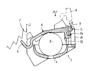
- Figure 1 shows a sectional side view of a ball
detector according to the invention; and
- Figure 2 shows a plan view of a locking lever
forming a component of a ball detector according to the
invention.
As can be seen from Figure 1, a ball detector for
a safety-belt band reeling mechanism for a motor vehicle
in particular comprises a supporting structure 1 having a
seat 2 for a ball 3 and a locking lever 4 articulated at
5 on the supporting structure and movable by means of the
ball 3 between a retracted position shown in this figure
and a position for locking the reeling mechanism, in which
the end 6 of the locking lever interacts with teeth of a
wheel 7 for locking the reeling mechanism.
According to the invention, the supporting struc-
ture possesses two arms, of which only one ~ is shown and
at the end of which are formed notches 9 for receiving pro-
jecting parts 10, 11 (Figure 2) of the locking lever 4,
which, for example, are moulded in one piecs with the
latter. These projecting parts 10 and 11 constitute the
rotation axle of the locking lever 4 on the supporting
structure.
Moreover, the lever 4 also has a hook 12 designed
to interact with a stop surface 13 of the supporting
structure, extending under the rotation axle of the lever
on the supporting structure. This hook and this stop
surface of the supporting structure makes it possible to
; keep the projecting parts 10, 11 of the lever in position
in the notches 9 of the arms of the supporting structure.
Once the ball detector has been mounted on the
reeling mechanism, the locking lever 4 can no longer come
loose from the supporting structure. In fact, for example
in the event of overturning the motor vehicle, the end 6
of the locking lever comes to bear against the locking
wheel 7 of the reeling mechanism, thus locking the latter,
and at the other end the hook 12 of the locking lever and
the stop surface 13 keep it in position.
,

1 3~`j`702
In the embodiment illustrated, the stop face con-
sists of a face of a locking rod extending between the
two arms of the supporting structure under the rotation
axle of the lever, and the notches open out at the end of
the arms. Other embodiments are possible.
The lever 4 is installed on the suPporting struc-
ture before the detector is mounted on the reeling mechanism
by offering the lever in the way represented by dot-and-
dash lines in Figure 1, introduc;ng the projecting parts
of the latter into the notches of the arm accordir~ to the
arrow A and then causing the lever to pivot according to
the arrow B so as to bring the hook into engagement with
the stop surface.
It will thus be appreciated that the production
of the component parts of this detector is easy and does
not require highly complex equipment to carry it out, and
that the mounting of the lever on the supporting structure
is very easy and very quick.

Representative Drawing
A single figure which represents the drawing illustrating the invention.
Administrative Status

2024-08-01:As part of the Next Generation Patents (NGP) transition, the Canadian Patents Database (CPD) now contains a more detailed Event History, which replicates the Event Log of our new back-office solution.

Please note that "Inactive:" events refers to events no longer in use in our new back-office solution.

For a clearer understanding of the status of the application/patent presented on this page, the site Disclaimer , as well as the definitions for Patent , Event History , Maintenance Fee  and Payment History  should be consulted.

Event History

Description Date
Inactive: Correspondence - MF 2010-08-10
Time Limit for Reversal Expired 2000-10-13
Letter Sent 1999-10-13
Grant by Issuance 1992-10-13

Abandonment History

There is no abandonment history.

Fee History

Fee Type Anniversary Year Due Date Paid Date
MF (category 1, 5th anniv.) - standard 1997-10-14 1997-10-06
MF (category 1, 6th anniv.) - standard 1998-10-13 1998-10-05
Owners on Record

Note: Records showing the ownership history in alphabetical order.

Current Owners on Record
ECIA - EQUIPEMENTS ET COMPOSANTS POUR L'INDUSTRIE AUTOMOBILE
Past Owners on Record
JEAN-MARCEL JOLY
Past Owners that do not appear in the "Owners on Record" listing will appear in other documentation within the application.
Documents

To view selected files, please enter reCAPTCHA code :


To view images, click a link in the Document Description column. To download the documents, select one or more checkboxes in the first column and then click the "Download Selected in PDF format (Zip Archive)" or the "Download Selected as Single PDF" button.

List of published and non-published patent-specific documents on the CPD .

If you have any difficulty accessing content, you can call the Client Service Centre at 1-866-997-1936 or send them an e-mail at CIPO Client Service Centre.


Document
Description 
Date
(yyyy-mm-dd) 
Number of pages   Size of Image (KB) 
Cover Page 1993-11-04 1 13
Claims 1993-11-04 1 21
Abstract 1993-11-04 1 17
Drawings 1993-11-04 1 16
Descriptions 1993-11-04 3 86
Representative drawing 2001-12-07 1 9
Maintenance Fee Notice 1999-11-10 1 178
Fees 1998-10-05 1 33
Fees 1997-10-06 1 36
Correspondence 2010-08-10 1 44
Fees 1996-09-17 1 31
Fees 1995-09-19 1 37
Fees 1994-09-20 1 41