Note: Descriptions are shown in the official language in which they were submitted.
1 30876~
The present invention relates to improvements in
cylindrical lock arrangements. The invention also relates
to improvements in permutation lock arrangements.
Some of the uses of such cylindrical lock
arrangements provide privacy lock-out systems. With a
cylindrical lock arrangement, this can be provided by a
mechanism which is activated by a push-button on the inside
door knob as will be further described below. The present
application is partially directed at novel lock-out
systems.
With permutation lock arrangements, of the type
as described for example in U.S. Patent 3,040,056,
Rosenhagen, June 26, 1962, the shaft of the outside door
knob is connected to the shaft of the permutation lock
chamber. The shaft of the chamber will rotate, thereby
permitting rotation of the outside door knob, only when the
correct combination of the permutation lock has been
punched in. Often, when the incorrect combination is
inserted, so that the knob will not rotate, the user will
apply excess force to the outside door knob to force the
chamber shaft to rotate. This can cause damage to the
chamber. It would therefore be desirable to provide means
for permitting the outside door knob to rotate, under such
conditions, without transmitting the rotating force to the
chamber shaft.
With permutation locks, it becomes necessary,
from time to time, to change the combination. It would
therefore be desirable to provide a cover which is eas;ly
removable by an adult, but which would présent difficulty
for a child to remove.
- 1 -
1 308762
It is a further object of the invention to provide
clutch means between a door knob shaft and the shaft of a
chamber of a permutation lock which permits rotation of the
chamber shaft with the door knob shaft when the chamber
shaft is not held against rotation, and which permits
rotation of the door knob shaft, without the chamber shaft,
when the chamber shaft is held against rotation.
It is a still further object of the invention to
provide an improved clutch means.
In accordance with a particular embodiment of the
invention there is provided a clutch connectable to a first
shaft at one end thereof and to a second shaft at the other
end thereof, said clutch engaging to rotate said second
shaft with said first shaft when said second shaft is not
held against rotation, said clutch slipping to permit
rotation of said first shaft without rotation of said second
shaft when said second shaft is held against rotation;
said clutch comprising:
a hollow outer cylindrical member having a closed
end and an open end, four slots, of equal length and width,
extending from said open end and longitudinally of said
cylindrical member and spaced 90 degrees from each other
around the periphery of said cylindrical member, said first
shaft being connectable at said closed end of said
cylindrical member;
a solid cylindrical inner core member insertable
into said hollow cylindrical member, from a first end
thereof, and having a first opening extending diametrically
through said core member transverse to the longitudinal axis
thereof at a first position of said core member, and a
~ ,B1~ - 2 -
1 308762
second opening extending diametrically through said core
mem:ber transverse to both said first opening and the longi-
tudinal axis of said core member;
a first ball bearing at one end of said first
opening and a second ball bearing at the other end of said
first opening and a first spring between said first and
second ball bearings urging said ball bearings away from
each other towards said hollow cylindrical member;
a third ball bearing at one end of said second
opening and a fourth ball bearing at the other end of said
second opening and a second spring between said third and
fourth ball bearings urging said third and fourth ball
bearings away from each other towards said hollow
cylindrical member;
the diameters of said ball bearings all being of
equal size and being greater than the width of said slots;
an expanded opening at the end of one of said
slots adjacent the open end of said hollow cylindrical
member, said expanded opening being large enough to permit
the passage of a ball bearing therethrough;
whereby to facilitate the loading of said ball
bearings and springs during assembly of said clutch.
In accordance with a further embodiment of the
invention there is provided a permutation lock arrangement
comprising;
a permutation lock chamber having a chamber shaft
extending therethrough, said chamber shaft being held
against rotation when the chamber is in a locked condition
and said chamber shaft being rotatable when said chamber is
in an unlocked condition;
- 2a---
~; L~
1 308762
an outer door handle having an outer handle shaft
extending therefrom and rotatable therewith;
clutch means connecting said outer door handle
shaft and said chamber shaft;
whereby, when said chamber is in its unlocked con-
dition and said outer door handle is rotated, said clutch
means engages and said chamber shaft rotates with said outer
door handle shaft; and
when said chamber is in its locked condition, and
the outer door handle is rotated, said clutch means slips to
permit rotation of said outer door handle shaft without
rotation of said chamber shaft;
said clutch means being connectable to said
chamber outer door handle shaft at one end thereof and to
said chamber shaft at the other end thereof, said clutch
means engaging to rotate said chamber shaft with said outer
door handle shaft when said chamber shaft is not held
against rotation, said clutch means slipping to permit
rotation of said outer door handle shaft without rotation of
said chamber shaft when said chamber shaft is held against
rotation;
said clutch means comprising:
a hollow cylindrical member having a closed end
and an open end, a plurality of slots of equal length and
width extending from said open end and longitudinally of
said cylindrical member and spaced 90 from each other
around the periphery of said cylindrical member, said outer
door handle shaft being connectable at said closed end of
said cylindrical member;
- 2b--
~LB.1~
1 3~8762
a solid cylindrical inner core member insertable
into said open end of said hollow cylindrical member, from a
first end thereof, and having a first opening extending
diametrically through said core transverse to the longi-
tudinal axis thereof at a first position of said core
member, and a second opening, at a second position of said
core member, extending diametrically through said core
member transverse to both said first opening and the longi-
tudinal axis of said core member;
a first ball bearing at one end of said first
opening and a second ball bearing at the other end of said
first opening and a first spring between said first and
second ball bearings urging said ball bearings away from
each other towards said hollow cylindrical member;
a third ball bearing at one end of said second
opening and a fourth ball bearing at the other end of said
second opening and a second spring between said third and
fourth ball bearings urging said third and fourth ball
bearings away from each other towards said hollow
cylindrical member;
the diameters of said ball bearings all being of
equal size and being greater than the width of said slots;
and
the second end of said solid cylindrical inner
core member being connected to said chamber shaft.
The invention will be better understood by an
examination of the following description, together with the
accompanying drawings, ln which:
FIGURE 1 is a perspective view of an arrangement
in which all of the above described
inventive features may be incorporated;
2c -
1 3~87~
FIGURE 2 is a cross-section through II-II of
Figure l;
FIGURE 2A is a perspective view of the lock rod
cylinder of Figure 2;
FIGURE 2B is a view similar to Figure 2 showing
the connector reversed;
FIGURE 2C is a perspective exploded view of the
connector and the outside drive
arrangement of Figure 2;
:~
:
,
,
:~
:;
- 2d_-
1 308762
FIGURE 3 is a cross-section to illustrate the
cover arrangement;
FIGURES 3A and 3B illustrate two different types
of openings for the cover arrangement;
FIGURES 4, 5 and 6 illustrate the clutch of
Figure 2;
FIGURES 7, 8, 9 and 10 illustrate one embodiment
of a lock-out system in accordance with
the invention;
FIGURE 7A is a perspective view of the U-shaped
member; and
FIGURES 11, 12 and 13 illustrate a second embodi-
ment of a lock-out system in accordance
with the invention.
Turning now to Figure 1, a lock arrangement,
illustrated generally at 1, is mounted on a door 3 and
includes an inner door knob/handle (hereinafter referred to
as knob 5), having a centrally located push-button 7, and a
~: push-button lock 9 having an outer door knob 11. The latch
20: 13 extends through an edge of the door 3.
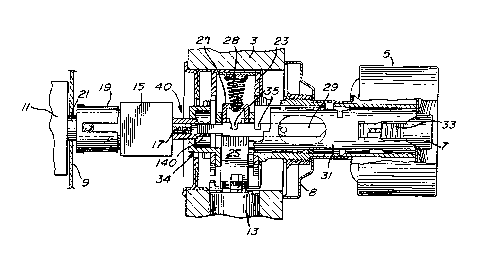
~ Turning to Figure 2, the push-button lock 9 com-
;~ prises a chamber 15 having a shaft 17 extending there-
: through and out both sides of the chamber. A clutch 19,
which will be more fully described below, connects the
~::
shaft 17 to the shaft 21 of outer door knob 11.
Disposed within a casing 23, which is mounted in
: the door, between the front and rear sides of the door, is
: a U-shaped latch retractor 25 which is better illustrated
~ in Figure 7. Disposed between the legs of the U-shaped
A ~ - 3
1 308762
latch retractor is a U-shaped member 27 having legs 128 and
sides 127 (see Figure 7A) whose function will be discussed
below.
The U-shaped member 27 is biassed outwardly
(towards the latch) by spring 28. Springs 30 (see Figure
7), bias the latch retracting member outwardly (towards the
latch edge of the door).
As is well known in the art, the inner end of the
latch is disposed between the legs of the latch retractor
so that, when the latch retractor 25 is retracted
inwardly (away from the latch edge of the door) against the
force of springs 30, latch 13 is retracted so that the door
can be open. When the latch retractor 25 is retracted,
spring 28 will for~e U-shaped member 27 outwardly (towards
the latch edge of the door).
When the latch retractor 25 is in its normal
position (not retracted), U-shaped member 27 is maintained
in its position abutting the inner side of the U-shaped
latch retractor by lock rod 29 which extends through lock
rod cylinder 31. As can be seen, lock rod cylinder 31
extends coaxially with the inside door knob from the inside
door knob through one side of the inside door knob and into
the door, and the lock rod cylinder 31 is rotatable with
the door knob. Push-button 7 extends coaxially with the
door knob from cylinder 31 and out of the cylinder and
through the other side of the door knob. The push-button
is rotatable with the cylinder.
As seen in Figure 2A, lock rod cylinder 31 has
ears 32 at the inner edge thereof. When the inside door
knob 5, and thereby the cylinder 29, is rotated, one of the
ears 32 will engage one of the steps 26 of the U-shaped
- 4 -
~,
~A`-~
~,
1 308762
latch retractor and thereby cause the latch retractor to be
retracted inwardly. Because there are two ears 32, the
latch retractor will be retracted regardless of which
direction the inside knob 5 is rotated. Because of this
function of the cylinder, the lock rod cylinder is also
referred to as a drive cylinder, in this specific case, as
an inside drive cylinder.
Push-button 7 is biassed outwardly, through the
other side of the inside door knob, by spring 33. Lock rod
29 is connected to push-button 7 and knob 5, so that
cylinder 29, push-button 7 and lock rod 29 all rotate
together.
As seen in Figure 2, lock rod 29 includes
openings 35. When the pu5h-button, and therefore the lock
rod, is pushed inwardly, the sides 127 (see Figure 7A) of
U-shaped member 27 fall into the openings 35 and are main-
tained there by force of spring 28. Accordingly, the
push-button will remain locked in its inward position.
When the inside door knob 5 is rotated, the sides 127 of
U-shaped member 27 will no longer be disposed in the
openings 35 so that, the push-button will be released with
the inside knob rotated, and the push-button 7 will move
outwardly once again, by force of spring 33, to the
position illustrated in Figure 2.
As also seen in Figure 2, shaft 17 of the chamber
15 is connected, on the right-hand side thereof, through a
connector 40, to an outside drive arrangement 34. Thus,
the items numbered 21j 19, 15 and 40 comprise an outside
door knob drive means for driving the outside drive
arrangement. As seen in Figures 2B and 2C, the outside
-- 5
~ 308762
drive arrangement 34 comprises a drive member having an ear
36 and a cylindrical shaft 38. The connector 40 is adapt-
able to different door thicknesses by changing the
:
- 5a -
A
1 308762
effective length thereof. When mounted in a relatively
thin door, its shaft 140 is on the right-hand side (as in
Figure 2). When mounted in a thicker door, its shaft 140
is on the left-hand side (as in Figure 2B), thus increasing
the effective length of the arrangement by the length of
the shaft.
When chamber 15 is in its unlock position (i.e.,
the correct combination has been inserted), shaft 17 is
rotatable so that, when outside door knob 11 is rotated,
the rotation force will be transmitted from the shaft 21
through the clutch 19 to shaft 17 to connector 40 and
thereby to outside drive arrangement 34. Referring to
Figure 7, when the outslde drive arrangement 34 is rotated,
the drive member 36 will engage steps 26 of latch retractor
25 to thereby, once again, retract the latch retractor
which, in turn, retracts the latch so that, once again, the
door is open.
If, on the other hand, the chamber 15 is in its
lock condition (the correct combination has not been
inserted or the incorrect combination has been entered),
then shaft 17 will not be rotatable. Under this condition,
when outside door knob 11 is rotated, and shaft 21 is
rotated therewith, clutch 19 will slip so that the outside
door knob will rotate without rotation of the shaft 1?.
Referring now to Figures 4, 5 and 6, it can be
seen that the clutch 19 comprises a hollow outer cylindri-
cal drive member 37 and a solid inner cylindrical driven
core 39. The hollow outer cylindrical member 37 comprises
four slits 41, 43, 45 and 47 which extend longitudinally of
the cylindrical member 37 and which are spaced 90 degrees
1 308762
apart around the periphery of the cylindrical member 37.
Each of the slots 41, 43, 45 and 47 is of the same width
and length.
In accordance with an improvement, one of the.
slots (e.g. slot 41) includes an expanded opening 42 adja-
cent the open end of the cylindrical member 37. The
purpose of this expanded opening 42 will be discussed
below.
The core member 39 includes circular openings 51
and 53 which extend diametrically through the core member
39. The direction of the circular opening 51 is transverse
to the direction of the circular opening 53, and the
opening 51 is at one position of the core member 39 while
the opening 53 is at a second position of core member 39.
The clutch also includes ball bearings 55 and 57,
spaced apart by spring 59, and ball bearings 61 and 63,
spaced apart by spring 65. As can be seen, ball bearings
55 and 57 with intermediate spring 59 are disposed at
opening 53 whereas ball bearings 61 and 63, with inter-
mediate spring 65, are disposed in opening 51. Shaft 17
would be inserted into opening 60 at the outer end of the
inner core member 39. The inner core member, with the ball
bearings and the springs inserted, would be inserted into
the outer cylinder 37 until the inner end of the inner core
member 39 abuts the inner wall of the outer cylindrical
member 37. The ball bearings extend partially into one of
the slots 41, 43, 45 or 47. As will be quite clear, the
width of each slot must be less than the diameter of the
ball bearings. The diameter of the ball bearings will, of
course, all be the same size.
1 308762
In order to assemble a clutch which does not
include the opening 42, the ball bearings and springs are
inserted into their respective openings 51 and 53, and the
ball bearings must be held against the force of the springs
inside the inner core member 39 while the inner core member
is inserted into the outer cylindrical member 37. This is
a rather difficult procedure and not very easy to automate.
With the expanded opening 42, which would be
greater than the diameter of the ball bearings, the
assembly is made much simpler.
In assembling with the opening 42, the inner core
member 39 would be rotated so that it is aligned with the
opening 42, and the inner core member would then be
inserted into the cylinder so that opening 53 underlies the
opening 42. Ball bearing 55 would then be dropped through
the opening 42 into the opening 53, spring 59 would then be
inserted after which ball bearing 57 would be inserted.
Ball bearing 57 is then pressed down somewhat and the inner
core member 39 is pushed inwardly and rotated through 90
degrees. The inner core member continues to be pushed
inwardly until opening 51 underlies opening 42. Ball
bearings 61 and 63 and spring 65 are inserted into opening
51 as above, and the ball bearing 63 is then pushed down
and the inner core member 39 is pushed inwardly until its
inner edge abuts the inner wall of the outer cylindrical
member 37. As can be seen, the assembly has been made
simpler and is susceptable to automation.
In the operation of the clutch member, as the
ball bearings extend into,the slots, the inner core member
39 will have the tendency to rotate with the outer
cylindrical member 37. When shaft 17 (which extends into
-- 8 --
1 308762
opening 60) is free to rotate, and when shaft 67 is
rotated, the inner core member 39 will rotate with the
outer cylindrical member 37 so that shaft 17 will rotate
with shaft 67. However, when shaft 17 is held against
rotation (when the wrong combination has been entered or
push-button 7 has been depressed for lock-out), and a
rotating force is applied to shaft 67, outer cylindrical
member 37 will tend to rotate while inner core member 39
will be held against rotation. The rotation force of the
outer cylindrical member 37 will force ball bearings 55 and
57 inwardly towards each other against the force of the
spring 59, and will force ball bearings 61 and 63 inwardly
towards each ot'ner against the force of the spring 65 so
that the outer cylindrical member 37 alone will rotate,
i.e., the clutch will slip. Thus, returning to Figure 2,
outer door knob 11, and therefore shaft 21, will rotate
without transmitting the rotation force 'co shaft 17 and to
outside drive arrangement 34. Thus, the knob will rotate,
but the door will not open.
A first embodiment of a lock-out system is illus-
trated in association with Figures 7, 8, 9 and 10. These
Figures illustrate the modifications which would be made to
a cylindrical lock, for example, of the kind illustrated in
Figures 1 and 2, in order to implement the lock-out system
of the first embodiment.
In accordance with the invention, the U-shaped
latch retractor 25 is modified by including thereon a stud
69 on the inside door side of the latch retractor. The
locking rod, referenced in Figures 7 to 10 at 29', is modi-
fied by including thereon an L-shaped member 71. The modi-
fied lock rod 29' would extend through the lock rod
cylinder 31 in the same way as lock rod 29 does in Figure
~A - g
1 308762
2. Additionally, the U-shaped latch retractor 2S would be
encased in the casing 23 in the same way as it is in Figure
2. Thus, Figure 2 illustrates the environment of the
inventive lock-out system, while Figures 7 to l0 illustrate
the specific details thereof.
In operation, when push-button 7 is pushed in,
lock rod 29' moves leftwardly in the direction of the arrow
A in Figure 7. It will then assume the position illus-
trated in solid lines in Figures 8 and 9, i.e., the leg of
the L-shaped member will be disposed behind the stud 69.
Once again, the lock rod will be locked into its pushed-in
position when the legs of the U-shaped member 27 fall into
the openings 35 of the lock rod.
When the outside door knob is now rotated, and
drive member 36 attempts to retract the U-shaped latch
retractor 25 in the direction of arrow C, such retractive
motion will be prevented because the motion of the stud 69
is blocked by the leg of the L-shaped member 71. This
again will force clutch 19 to slip. Accordingly, the door
cannot be opened from the outside.
If, on the other hand, inside door knob 5 is
rotated in the direction of arrow B, lock rod 29' will also
rotate, in the direction of arrow B of Figure 8, so that
the leg of the L-shaped member will move out of the way of
the stud 69, and U-shaped latch retractor 25 will be
retracted in the direction of arrow C of Figure 8. Accord-
ingly, the door can be opened from the inside. At the same
time, lock rod 29' will be released so that the push-bl~t~n
will move outwardly due to the action of spring 33 as
above-described.
-- 10 --
t 308762
A second embodiment of a lock rod system in
accordance with the invention is illustrated in Figures 11,
12 and 13. In this embodiment the inside door arrangement
is the same as in Figure 2.
The outside drive arrangement 34 of Figure 2 is
replaced with the outside sleeve drive 79 illustrated in
Figures 11, 12 and 13. The outside sleeve drive 80
includes an ear 81 and slots 83.
Attached to shaft 17, through opening 18, is a
lock-out cam 85 having prongs 87 and biassed inwardly by
spring 88.
The lock rod 29 is modified by including at the
free end thereof a freely rotating cup ring 89. The cup
ring 89 abuts the lock-out cam 85 as seen in Figure 11.
Once again, push-button 7 rotates with inside
door knob S, and lock rod 29 rotates with push-button 7, so
that lock-out rod 29 rotates with inside door knob 5.
Lock-out cam 85 rotates with shaft 17, and prvngs
87 of lock-out cam 85 extend into slot 83 when the push-
button is not pushed in as seen in Figure 11. Accordingly,when the correct combination has been inserted into the
chamber 15 of permutation lock 9, and when outside door
knob 11 is rotated, lock-out cam 85 will also rotate to
rotate, in turn, outside sleeve drive 79. Ear 81 will
engage either one of the steps 26 to retract U-shaped latch
retractor 25 so that the door will be open.
When push-button 7 is pushed in, as shown in
Figure 13, cup ring 89 pushes lock-out cam leftwardly so
that prongs 87 are no longer in slot 83. Accordingly,
there is no longer any connection between the outside door
knob 11 and the outside sleeve drive 79. Thus, when out-
-- 11 --
...
1 308762
side door knob 11 is rotated under the above conditions,although the door knob will rotate, the U-shaped latch
retractor will not be retracted and the door will not open.
Thus, the door cannot be opened from the outside under
these conditions even when the correct combina~ion has been
inserted into the permutation lock.
A cover arrangement for a lock or the like in
accordar,ce with the invention is illustrated in Figures 1
and 3. Referring to these Figures, the cover arrangement
comprises a cover member 8 having indents 99 at the top end
thereof. Preferably, there are two such indents equally
spaced from the side edges of the cover member. The cover
member also has a bottom opening 101. Different shapes for
the opening are shown in Figures 3A and 3B. Obviously,
other shapés could also be used.
Referring to Figure 3, the cover arrangement also
includes a door mounted plate 103 which has openings 105
which are aligned with the indents 99. A spring 107 is
mounted on the plate 103 and is adapted to extend from the
plate member and outwardly of the cover member 8 through
the opening 101 thereof.
In operation, the cover member is placed over the
plate top end first so that the indents 99 extend into the
openings 105. The bottom end is then pivoted so that the
spring 107 extends out through the opening 101. (It will
of course be appreciated that the cover member is mounted
on the plate before the inside door knob 5 is mounted.)
The force of the spring will maintain the cover
arrangement closed against removal by application of a
small force which might be applied, for example, by a
child. However, applying enough force to overcome the
1 308762
holding power of the spring, which could easily be applied
by an adult, will serve to remove the cover member from the
plate.
Although several embodiments have been described,
this was for the purpose of illustrating, but not limiting,
the invention. Various modifications, which will come
readily to the mind of one skilled in the art, are within
the scope of the invention as defined in the appended
claims.
- 13 -