Note: Descriptions are shown in the official language in which they were submitted.
~L3~1~3136~
Hospital Bed Convertible to Chair
BACKGROUND OF THE INVEMTION
This invention relates to a hospital bed
that is convertible to a chair. The structure of the
present invention is primarily useful for facilitating
getting a patient from a supine position on the bed to
a standing and/or walking position.
In the present practice, two nurses are
preferably employed in assisting a patient's moving
from a supine position to a standing position. This
is particularly true for a patient who has been in the
supine position for a long period of time. In many
instances, the patient in that condition simply does
not want to stand because it is painful.
To get the patient to a standing position~
the bed is lowered. The side rails of the bed are
dropped. The patient is then pivoted or swung through
90 so that the patient's legs hang over the side of
the bed. Even in its lowered position, the patient's
feet most likely will not rest firmly on the floor.
Therefore, in addition to hurting, the patient is
'
gL3~386~
apprehensive about sliding off the bed without knowing
when his feet will touch the floor.
In this attitude, attendants assist the
patient in getting his feet on the floor as he slides
off the bed. The attendants cannot lift directly
since they are at the edge of the bed and the pa~
tient's weight is centered inward of the edge of the
bed. If the patient should start to fall, the atten-
dant must hold the patient firmly while at the same
time bracing himself in a somewhat awkward position.
This movement will sometimes lead to bac~ injury of
the attendant.
BRIEF DESCRIPTION OF THE INVENTION
An objective of the present invention has
been to convert a hospital bed to a chair with the
conventional head panel of the hospital bed function-
ing as the back of the chair so that the patient can
exit the bed from the foot of the bed. By providing
for conversion to a chair in this fashion, the patient
can simply be eased into an upright sitting position
from which exit from the chair is easily achieved with
attendants at the side of the "chair" in a much more
favorable position for lifting or supporting the
patient.
Another objective of the invention has been
to provide a foot panel in addition to the convention-
al patient support panels, that is, the head, seat,
thigh and calf panels normally found in ho~pital beds.
13~)~3866
--3--
A foot panel is maintained in a horizontal position as
the panels are shifted from bed to chair position so
that as the patient is moved gently to a sitting
position, the foot panel swings into engagement with
the patient's feet, thereby giving the patient a sense
of security, that is, being under control and not
having dangling feet that must somehow reach the
floor.
Still another objective of the present
invention has been to provide for a hospital bed that
converts to a chair while still providing the normal
hospital bed articulating functions, specifically
including the raising of the back and the raising of
the patient's legs.
These objectives of the present invention
are attained by providing a retracting frame on the
normal bed fixed frame. The conventional seat panel
is fixed to the retracting frame. The head panel is
pivoted to one end of the seat panel. The thigh panel
is pivoted at the other end of the seat panel~ the
calf panel is pivoted to the thigh panel and the foot
panel is pivoted to the calf panel. Control links are
connected between the fixed frame and the thigh panel,
and a hydraulic cylinder and piston are provided for
moving the retracting frame longitudinally with
respect to the fixed frame, that movement causing the
back panel to pivot upwardly and the calf panel to
pivot clownwardly. The control links also serve to
' ~:
~ ~0886~
hold the calf panel in a horizontal attitu~e when the
patient support is in a bed position.
A parallelogram linkage between the seat
panel and the foot panel maintains the foot panel in a
horizontal attitude at all positions of the patient
support panels.
The parallelogram linkage is in two sections
which are pivotally interconnected at an intermediate
floating link. The floating link permits a flexure of
the parallelogram linkage to permit the intermediate
thigh panel to be angled upwardly to raise the pa-
tient's legs in the bed position, and to permit the
calf panel to drop down when going to the bed posi-
tion.
A conventional hydraulic cylinder and piston
is provided for raising the head panel during a normal
bed operation when the patient si~ply wants to have
his head and back raised for greater comfort. Slotted
links connect the head panel to the power for bed
conversion and power for sea~ conversion so that the
head panel can be raised in either of the two opera-
tions without interference.
In the preferred form of the invention, the
patient support panels are mountad on the basic catilever
structure o~ U.S. Patnet No. 4,751,754 issued June 21,
1988. That basic structure is d~signed to receive a variety
~,~, .. .
~308~36~
of type~s of beds. The base consists of a base frame
that is mounted on casters. A cantilevered support
arm and stabilizing frame form a parallelogram linkage
that is secured at one end to the foot end o~ the base
frame. The upper er.d of the parallelogram linkage is
connected to a fixed frame. In the conventional bed,
four panels forming the patient support are supported
on the fixed frame with the leg panels overlying the
foot end of the base frame.
In using the base frame with the present
invention, the retracting frame is mounted on the
fixed frame and the seat panel is fixed to the re-
tracting frame. The orientation of the patient
support panels is reversed so that the foot end of the
patient support panels projects beyond the upper end
of the parallelogram linkage permitting the calf and
foot to swing down without interference from the
parallelogram linkage.
In the preferred form of the invention,
controls are provided that will prevent the patient
from inadvertently converting the bed to a chair
position. More specifically, the hydraulic system is
such that the fluid must be pumped manually to change
the panels to a chair configuration.
The several features of the invention will
become more readily apparent from the following
detailed description taken in conjunction with the
accompanying drawings in which:
~3(~ 36~i
--6--
~ Fig. 1 is a side elevational view of the bed
with panels in a sitting position;
Fig. 2 is a side elevational view of the bed
in its lower position with the panels horizontal;
Fig. 3 is a side elevational view of the bed
converted to a chair position;
Fig. 4 is an enlarged fragmentary view
similar to Fig. 2;
Fig. 5 is a fragmentary plan view taken in
the direction of the arrows of 5-5;
Fig. 6 is a cross-sectional view taken along
lines 6-6 of Fig. 5;
Fig. 7 is a cross-sectional view taken along
liens 7-7 of Fig. 4;
Fig. 8 is a fragmentary side elevational
view of an alternative embodiment; and
Fig. 9 is a view similar to Fig. 8 showing
the thigh panel in elevated position.
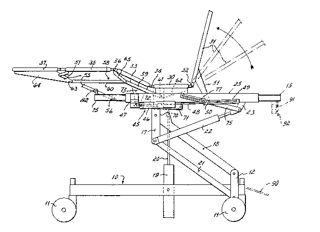
Referring to Fig. 1, the bed has a base
20 frame 10 supported on casters 11. The base 10 has an
upwardly-projecting fixed bracket 12 at its head endu
A fixed bed frame 15 is pivotally mounted at 16 (Figs.
3 and 4) to a depending fixed bracket 17. A canti-
levered support arm 18 is connected between the
25 brackets I2 and 17. A hydraulic cylinder 19 is
mounted on the base and has a piston rod 20 that
engages the support arm 18 to raise and lower it. A
stabilizing arm 21 is connected between the brackets
t,
~L3~ 366
--7--
12 and 17 so that the arms 18 and 21 together with the
brackets 12 and 17 provlde a parallelogram lin~age
that supports the fixed frame 15 in a horiæontal
attitude whether the fixed frame is in a raised
position as shown in Fig. 1 or in a lowered position
as shown in Fig. 2. A piston and cylinder 22 is
connected between bracket 17 and fixed frame 15, via
~racket 23, to brace the fixed frame normally in a
horizontal position. As the piston and cylinder 22 is
retracted, the foot end of the fixed frame ls raised,
placing the bed into the trendelenburg position; if
extended, the head end is raised to the reverse
trendelenburg position. The base frame 10, the fixed
frame 15, and the linkage and hydraulic cylinder to
raise and lower the fixed frame with respect ~o the
base frame corre~ponds to structure shown in U.S. Patent
No. 4,7~1,754 issued June 21, 1988.
A retracting frame 25 is slidably mounted on
the fixed frame 15. Referring to Fig. 7, the retract-
ing frame 25 is channel-shaped and carries at least
rollers 26 at its four corners. The rollers cooperate
with the fixed frame 15, which is channel-shaped and
inside the channels of retracting frame 25, to support
the retracting frame 25 on the fixed frame with the
capability of movement with respect to the fixed
frame.
A seat panel 30 is fixedly secured to the
retracting frame 25. A head panel 31 is pivotally
. .
~3~886~
connected by a hinge 32 to the seat panel 30. A thigh
panel 33 is connected by a hinge 34 to the seat panel
30. A calf panel 35 is connected by a hinge 36 to the
thigh panel 33 and a foot panel 37 is connected by a
hinge 38 to the calf panel 35. A centrally mounted
double-acting piston and cylinder 40 is connected
between the fixed frame :L5 and the retracting frame
25. More speciically, a cylinder 41 is pivoted to a
cross member 42 that forms part of the fixed frame 15.
A piston rod 43 is pivotally connected to a bracket 44
that depends from the seat panel 30, the seat panel 30
being fixed to the retracting frame 25.
The patient support panels are connected to
piston and cylinders for conventional bed operation,
as will be described. A pair of pistons and cylinders
45 are pivotally mounted at each side of the retract-
ing frame 25. A cylinder 46 is mounted to a bracket
47 fixed to the retracting frame 25. A piston rod 48
is connected to a slotted bed link 49 that receives a
pin 50 fixed to a bracket 51, the bracket 51 being
fixed to the head panel 31 of the patient support.
When the retracting frame 25 is in its retracted
position as shown in Figs. 1, 2 and 4, an extension of
the piston rod 48 will cause the link 49 to push upon
pin 50, thereby rotating the bracket 51 and panel 31
from the position of Fig. 2 to the position of Fig. 1.
A control link 55 is pivotally connected at
each side of the fixed frame between the fiY.ed frame
-,
~3~8~36$
15 at 5~ and a bracket 57 fixed to the calf panel 35.
When the retracting frame 25 is in its retracted
position of Fig. 1, the control link 55 provides the
support for the thigh and calf panels 33, 35, main-
taining them in horizontal position.
Foot panel 37 is supported, on each of itssides, in horizontal position by a parallelogram
linkage 58 which includes thigh panel 33 and calf
panel 35 on one side and links 59 and 60 on the other
side. Link 59 is pivoted at 61 to a bracket 62 fixed
to seat panel 30 and, hence, to the retracting frame
25. Link 60 is pivoted at 63 to a bracket 64 fixed to
the foot panel 37. A floater link 65 is pivotally
connected between the thigh and calf panels 33 and 35
and the two links 59, 60, respectively, to maintain
the parallelogram linkage relationship (creating two
end-to-end parallelogram linkages having the common
link 65) while permitting panels 33 and 35 to flex
with respect to each other, as shown in Fig. 1. A
piston and cylinder 70 is pivotally mounted on a
bracket 71 fixed to the seat panel 30 and hence to the
retracting frame 25. The piston has a rod 72 pivoted
to a bracket 73 fixed to the thigh panel 33. When the
piston and cylinder 70 is actuated, the thigh panel 33
will rotate clockwise as shown in Fig. 1 to raise the
thigh panel 33, calf panel 35l and foot panel 37 to
the attitude shown in Fig. 1.
- :
.
-10-
Thus, through the actuation of the piston
and cylinder 45, conventional head panel operation is
obtained and through the actuation of the piston and
cylinder 70, conventio~al operation of the thigh and
calf panels is obtained, with the control link 55
providing the necessary support and mechanical lift
for the thigh and calf panels.
A slotted chair link 75 is pivoted to the
bracket 23 fixed to the fixed frame 15. The link 75
has a slot 77 which receives the pin 50 connected to
the head panel bracket 51. As shown in Figs. 2 and 4,
the pin 50 is at the left-hand of the slot 77 when the
patient support panels are all in a horizontal atti-
tude. When the retracting frame 25 is extended, that
is, driven to the left (compare Figs. 2 and 4 with
Fig. 3), the seat panel 30 fixed to frame 25 will pull
the head panel 31 and its bracket 51 against the link
75, thereby causing the head panel 31 to pivot to a
generally vertical attitude as shown in Fig. 3. The
slot in the link 49 also permits the pin 50 to slide
the extent necessary to raise the head panel 31.
When the retracting frame 25 moves to the
foot end of the fixed frame, as shown in Fig. 3, the
control link 55 will cause the calf panel 35 to swing
down to a slightly inclined but generally vertical
attitude. The foot panel 37 will remain horizontal
due to the parallelogram linkage 58 connecting it to
the seat panel 30.
, ,~,,, ,, " , ~ ,,, "~ ", ~ " , " ,,~ ,; ,""", ,;,~", , ,,, ~ ,
'
,
~ - ' ' ' '
1.3~ i6
Each of the patient support panels has a
rigid cover removably mounted on the panel. The cover
for the -thigh panel 33 is shown at 80. Mattress
cushions (not shown) will overlie the panel covers for
the patient's comfort. The panel cover 80 has on its
undersurface one or more cam tracks 81. One or more
rollers 82 mounted on the fixed frame ]5 is engageable
by the cam track 81 so that when the retracting frame
is moved to the extended position, the roller
operating on the cam track 81 will cause the panel 80
to pivot upwardly, thereby raising the patient's
thighs so that the patient will not think he or she is
sliding off the bed prematurely. In an alternative
structure, a roller similar to roller 82 could be
provided to act on a cam on the thigh panel 33,
thereby raising the thigh panel 33 diractly when the
retracting frame 25 is operated.
A further alternative embodiment of appara-
tus for lifting the thigh panel when converting to a
chair position is illustrated in Figs. 8 and 9.
There, a stop 93 extends across the frame 10 adjacent
the control link 55. The stop 93 restricts the
downward pivoting movement of the control link 55 and
is positioned so as to be engaged h~ the control link
55 before the calf and foot panels reach their final
position.
The relationship of the elements at the time
the control link 55 contacts the stop 93 is
`-, ` '~ ."' .
130~36~
-12-
illustrated in Fig. 8. Thereafter, the retracting
frame 'S slides forward an additional two inches or
so. In that forward thrust, the end of the now
immobile control link 55 acts as a fulcrum about which
the calf panel 35 pivots. As the calf panel 35 swings
upwardly from the position of Fig. 8 to the position
of Fig. 9, it inevitably raises the thigh panel 33 to
an upwardly-inclined position to provide the patient
with the comfortable feeling that he or she will not
slide off the bed prematurely.
-Thus, it can be seen from Fig. 3 that by
simply extending the retracting frame 25, the patient
support can be changed from a horizontal bed attitude
to an upright chair attitude. In this attitude, the
foot panel 37 is about 4 inches above floor level.
The paLient's feet will normally be on the foot panel
so that the patient has the security of knowing that
he or she will not be involved in a free fall while
sliding off the bed in order to get to a standing
position.
If the structure of U.S. Patent No. 4,751,754,
issued June 21, 1988, is compared with the structure
disclosed herein, it will ~e seen that in the
bed ol the '75~ Patent, the foot end of the
patient support overlies the connection of the canti-
levered support arm to the base frame. With that
configuration, the patient's chest is available for
X-rays. That attitude would not be suitable for the
:'
.
~. :
8~366
chair-bed configuration because the cantilevered
support structure would impede the lowering of the
foot, calf and thigh panels. Accordingly, the atti-
tude of the panels is reversed ~lith respect to the
base frame.
In the preferred form of the invention, the
hydraulic cylinder 41 that causes the movement of the
retracting frame 25 is preferably operated by a foot
pump 90 so that only an attendant can change the bed
to the chair attitude of Fig. 3. A selector valve 91
is provided to switch the system to a chair mode of
operation (using a hydraulic system similar to that of
the '754 Pa~ent), and another selector val~e 92
is provided to switch the double-acting cylinder 41 to
either an "up" mode of operation or a "down" mode of
operation once the choice has been made to switch the
system to the chair mode of operation.
In the operation of the invention, the
cylinder 19 is actuated to raise the bed to a normal
bed height. In that raised position, the panels may
be completely horizontal or can be changed to a
sittir.g-up position as shown in Fig. 1. That change
is effected by operating the cylinder 46 to raise the
head panel 31 by pushing on bracket 51. That mo~ement
25 of bracket S1 is permitted by the slot 77 in link 75.
The thigh panel 33 may be independently raised by
actuation of the cylinder 70.
,.. 0. . '
'
.
' ' '
~l308B6~
-14-
If the patient is to be assisted from the
bed, the bed is lowered to the position of Fig. 2.
The retracting frame 25 is extended with respect to
the fixed frame. In extending the retracting frame
25, two articulations of the patient support panels
occur. Head panel 31 is swung to an upright position
by the bracket 51 being pulled against the end of the
slot 77 in link 75. The slot in the link 49 permits
that movement.
The control link 55, coupled with the
movement of the seat panel 30 forward, causes the calf
panel 35 to swing downwardly, carrying with it the
foot panel 37. The foot panel 37 is maintained in a
horizontal attitude because of the parallelogram
linkage 58 connecting it to the seat panel 30. The
thigh panel cover 80 is raised slightly by cam track
81 rolling upon roller 82 so as to raise the patient's
thighs slightly to provide the comfort of knowing that
the patient will not slide off the chair.
With the patient in a sitting up position,
attendants at either side of the patient, who can
stand quite close to the patient because of the
narrowness of the patient's bed, can ease the patient
to a standing position. Since the patient's feet are
in contact with the foot panel 37, the patient's fear
of falllng to the floor is minimized. Once the
patient is standing, it is of course a very short
. .
:~
- ~.3~
-15-
step, approximately four inches, to the floor in front
of the bed.
From tha above disclosure of the general
principles of the present invention and the preceding
detailed description of a preferred embodiment, those
skilled in the art will readily comprehend the various
modifications to which the present invention is
susceptible. Therefore, I desire to be limited only
by the scope of the following claims and equivalents
thereof:
';';
- . ,