Language selection

Search

Patent 1309009 Summary

Third-party information liability

Some of the information on this Web page has been provided by external sources. The Government of Canada is not responsible for the accuracy, reliability or currency of the information supplied by external sources. Users wishing to rely upon this information should consult directly with the source of the information. Content provided by external sources is not subject to official languages, privacy and accessibility requirements.

Claims and Abstract availability

Any discrepancies in the text and image of the Claims and Abstract are due to differing posting times. Text of the Claims and Abstract are posted:

  • At the time the application is open to public inspection;
  • At the time of issue of the patent (grant).
(12) Patent: (11) CA 1309009
(21) Application Number: 610257
(54) English Title: ARRANGEMENT IN CONNECTION WITH AN ADJUSTABLE BACK REST CUSHION FOR A CHAIR
(54) French Title: MONTAGE RELIE A UN COUSSIN DE DOSSIER REGLABLE POUR CHAISE
Status: Expired
Bibliographic Data
(52) Canadian Patent Classification (CPC):
  • 155/51.1
(51) International Patent Classification (IPC):
  • A47C 7/46 (2006.01)
(72) Inventors :
  • ASBJõRNSEN, SVEIN (Norway)
  • LADE, JAN (Norway)
  • ASBJõRNSEN, SVEIN (Norway)
(73) Owners :
  • ASBJõRNSEN, SVEIN (Norway)
  • JAN LADE A/S (Norway)
(71) Applicants :
(74) Agent: GOWLING LAFLEUR HENDERSON LLP
(74) Associate agent:
(45) Issued: 1992-10-20
(22) Filed Date: 1989-09-05
Availability of licence: N/A
(25) Language of filing: English

Patent Cooperation Treaty (PCT): No

(30) Application Priority Data:
Application No. Country/Territory Date
883983 Norway 1988-09-07

Abstracts

English Abstract


A B S T R A C T.

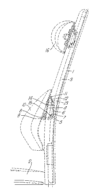
An arrangement in connection with an adjustable back
rest cushion (10,16), where the cushion is connected
with a slide means (4,5) which may be moved in a guide
(3) forming part of the back rest (1), said guide (3)
consisting of a contoured rail spaced from the back
rest front, said slide means (4,5) consisting of two
members, viz. a slide member (5) which is designed to
be movable in a groove in said rail, solely in the
longitudinal direction of said rail, and a cushion
holder member (4), which at its rear portion is
pivotably attached (14) to one end of a front portion
of slide member (5), and is lockable by the aid of a
snap lock means (15, 15', 15") to the other end of said
front portion of slide member (5), the front portion of
cushion holder member (4) being provided with means (8)
for engagement with cushion rear side (9).

(Figure 1)


Claims

Note: Claims are shown in the official language in which they were submitted.


WHAT IS CLAIMED:

1. An arrangement in connection with a height adjustable
back rest cushion, where said cushion is connected with a slide
means which is slidable along a guide forming part of the back
rest, and where said cushion may be moved relative to said slide
means, in which said guide is a contoured rail which is provided
at a rearward distance from the front of the back rest, said
slide means comprising two members consisting of a slide member
which is designed to move in a groove in the rail solely in the
longitudinal direction of said rail, and a cushion holder member
the rear portion of which is pivotably attached to one end of a
front portion of the slide member and is lockable by the aid of
a snap lock means to the other end of said front portion of the
slide member, the front portion of the cushion holder member
being provided with means for engagement with the rear side of
the cushion.

2. An arrangement as stated in claim 1, where the slide
means is slidable in a longitudinal aperture in the back rest,
and in which said aperture is closable at the front face of the
back rest.

3. An arrangement as stated in claim 1, in which a first
engagement member is provided in a groove of said rail, and in
which a second engagement member is provided in the rear portion
of cushion holder means, said means engaging at said snap
locking.

4. An arrangement as stated in claim 1, in which the first
engagement member is a toothed rack or a toothed belt, and in
which the second engagement member is a toothed rack segment.

5. An arrangement as stated in claim 4, in which said
first engagement member is firmly provided in said groove.

6. An arrangement as stated in claim 3 or 4, in which said
first engagement member is a toothed belt which is movable along
said groove in rail by the aid of a toothed wheel which is
driven by a selectively controllable motor.

- 6 -

7. An arrangement as stated in claim 1, 2 or 3, in which
said first engagement member consists of a long screw extending
along a substantial portion of the back rest height and is
rotated by a selectively controllable motor, said second
engagement member consisting of a nut segment.

8. An arrangement as stated in claim 1 or 2, in which on
the rear portion of the cushion holder member a friction member
is provided which in case of said snap locking penetrates into
said groove and forms a frictional contact with the groove
bottom in rail.

9. An arrangement as stated in claim 2, in which said
aperture is closable by zipper means, and in which a holder
member is provided at the upper and lower end portions of the
slide member, respectively, each said holder member having a
receiving opening for a gripping member of said zipper means,
said opening facing obliquely outwards the front of the back
rest.

-7-

Description

Note: Descriptions are shown in the official language in which they were submitted.


1 3nqoO9

An arran~ement in connection with an ad~lustable_back rest
cushion _ a_chalr.

The present lnvention relates to an arrangement in con~ection
5 wlth a height ad~ustable back rest cushlon, sald cushion
belng connected with a slide means which ls slldable along a
~uide constltuting part of the back rest, a~d where said
cushion may be moved relative to said sllde means.

tO Several such arrangements are previously known, inter alla,
from N0-PS 149 608.

For a long time~ however, it was desired that such back rest
cushions should be ad~ustable elther manually or electrically
and that lt should, at the same time be possible to lock the
cushion(s) relative to the back rest.

According to the present invention lt ls proposed that sald
gulde is a contoured rall which is provided at a rearward
20 distance from the back rest front, that the slide means is a
two-plece means comprising a slide member designed to be
moved in a groove in the rail only in the longitudinal
dlrection of the rail, and a cushion holder member the rear
portion of which is pivotably attached to one end of a fro~t
25 portion of the slide member and is lockable by snap locklng
to the other end of said front portion of the slide member,
the front portion of the cushion holder member being provided
with means for engagement with the rear side of the cushion.

30 The invention also indicates means for closing the opening
appearlng on the front of the back rest, on top, and below
the back rest cushion, respectively.

These and further characterizing features of the present
35 lnvention will appear from the following clalms as well as
- from the i`ollowing description wlth reference to attached
drawlngs.

1 3~qonq


Flgure 1 shows a phantom ~iew, as seen from one side,
of a first embodiment of the arrangement
according to the lnventlo;n.
Figure 2 lllustrates a chalr having a back rest and back
rest cushlons provided and supported accordlng
to the present lnvention.
Figure ~ is an enlarged section of the arrangement
accordlng to the invention as shown in Figure 1.
Figure 4 ls a cross sectlon of the arrangement of Flgure
1û 1.
Figure 5 lllustrates the arrangement o~ Figure 3 ln a
front vlew~ and Flgure 5a is shown for
completeness and corresponds to Figure 4.
Figure 6 shows a modlflcatlon of the embodlment shown ln
Figure 5 and is intended for motorized
dlsplacement of the back rest cushion.
Flgure 6a ls shown for completeness and corresponds to
Figure 5a.
Figure 7 illustrates another embodlment utilizlng the
2D screw principle for motorized displacement of
the back rest cushion.
Figure 8 is a cross sectional view of the arrangement of
Figure 7.
Figure 9 illustrates the arrangement of Figure 7 in a
front view, and
Flgure 9a ls shown for completeness and represents a
diminution of Figure 8.
Figure 10 shows a third embodiment of the arrangements
accordi~g to the invention where dlsplace-
ment should be manual and the cushion is
locked ln place by the ald of a specla~ friction
member.
Flgure 11 shows the arranement of Figure 10 in cross
section.
35 Figure 12 iS a front view of the arrangement of Flgure 10,
and Flgure 12a ls a cross sectional vlew of the
arrangemen-t in dlminut'lon relative to Flgure 11.

1 3cqO09


In the chalr comprislng a back rest 1 and a seat 2, a
contoured rall 3 is provlded ln back rest 1 at a dls-tance
from the front slde of the back restO A toothed rack or
toothed belt 6 may be provided lnside the contoured rail. A
5 slide means ls used for displacing back rest cushlon 10 and
conslsts of a cushion holder member 4 which ln lts front
portion is provided with member 8 intended for engagement
with a support plate 9 for cushlon 10 ! as clearly appearing
from Figure 1. The slide means, additionally, comprises a
10 slide member 5 which at its rear portion is provided with a
toothed rack segment 7 which is shaped for selectlve
engagement with toothed rack or toothed belt 6. The two parts
of the slide means are pivotably connected by the aid of a
hinge 14, which ls preferably provided at the upper portion
15 of the slide means. At the lower por-tion of slide means a
snap lock is provided comprising a pln portion 15' and a
clamp portlon 15". To displace the back rest cushion lt is
pulled out of the back rest at its lower por-tion causing snap
engagement 15 to be temporaril~ opened. The cushion ls then
20 moved to a desired position, and the lower portion, of the
cushion is pushed ~owards the back rest, to cause a snap
reengagement.

By ensuring that the slide means is only in contact with a
25 groove in rail 3 at the end portions of the slide member,
whereas there is a certaln clearance between slide member and
rail between said end portions, slide member 5 can also move
across curved portions of back rest 1, as will appear from
Figure 1.

In order to prevent any opening in the back rest above and
below back rest cushion 10, a zipper 11 may be provlded along
the length of the back rest,.as shown in Figure 2. Gripping
member 12 of the zipper is adapted to be inserted into and
35 firmly held in an incllned position b~ a holder member 13
whlch ls provided a~ the respectlve ends of slide member 5.
Such an incllned posltion of zipper member 12 results in ver~

1 3C'~009


simple operatlon of the zlpper. This arrangement of the
zlpper and lts actuatlng members provides the advantage that
the front face o~ the back rest appears as an lntegrate
surface, and that fingers or extraneous matter are prevented
5 from enterlng into the slot along which slide means 4,5 is to
move along the height of the back rest.

In Figure 1 two back rest cushions are shown, viz. a cushion
10 for loin, and a cushion 16 for the back of the head 16.
The principles for locklng and displacement, however, are as
dlsclosed above in connection with cushion 1~.

As will appear ln more detail from Figure 3, zipper member lZ
is firmly held in holder member 13 b~ the ald of a snap lock
13' engaging the openlng of member 12. The locking portlon
17 of the zipper ls mounted on member 12 in a conventional
manner. When the cushion is moved upwards, the uppermost
zipper element 17 will, thus, cause opening of the zipper,
whereas the lowermost element (not shown) will cause -the
2D zip~er to be locked as the cushion is moved upwards. The
back rest face will, thus, all the time appear as an
integrate closed surface, independently of any upward or
downward movement of the cushion.

25 It will appear from Figure 5 that the cushion is to be moved
by hand upwards or downwards along toothed belt 6 or toothed
rack, as mentioned in connection with Flgure 1.

In Figure 6, however, it is intended that it should not be
30 necessar~ to disengage the lower portion of holder member and
slide member to move the cushlon. To this end engagelng
element S should be a tvothed belt engaging toothed rack
segment 7. Toothed belt 6 may be arranged to ~e an endless
belt or a belt which ls spring influenced to ensure that the
35 belt is tensioned all the time~ A toothed wheel 18 is driven
by a motor 19 to displace belt 6 upwards or downwards, and
cushion 10 and/or cushlon 16 correspondingly. If desired,

1 3IJ~OO9


lndivldual displacement Qf cushlons 10 and 16 ma~ be
provlded, and this should be achleved b~ respective drlving
means, as shown ln Figure 6.

5 The embodiment shown ln Figure 7 will be descrlb~d inasmuch
as lt dlffers from the previously mentioned embodiment~.
Toothed belt 6 ls here replaced by a screw whlch is actuated
b~y a motor 21 (see Flgure 9), and slide member 5 ls provided
with a member 22 corresponding to a nut segment for engage-
ment with screw 20. When screw 20 ls rotated in its gulde, as
shown in Flgure 8, slide member 5 will, due to member 22,
move upwards or downwards along the screw, as determlned b~
the sense of rotatlon.

~5 Figure 10 shows a simplified embodiment where no members are
provided in the rail to displace the cushion in the manner of
the previous embodiments. On the other hand, a friction block
23 is provided on slide member 5. In case of a snap engage-
ment between members 15' and 15" on hol.der member 4 frlction
2~ block 23 will be urged with a certain force towards ~he
bottom of rail 3. The concept of Figures 10, 11, and 12,
thus, represents solely manual displacement of the cushion.


3~


Representative Drawing
A single figure which represents the drawing illustrating the invention.
Administrative Status

For a clearer understanding of the status of the application/patent presented on this page, the site Disclaimer , as well as the definitions for Patent , Administrative Status , Maintenance Fee  and Payment History  should be consulted.

Administrative Status

Title Date
Forecasted Issue Date 1992-10-20
(22) Filed 1989-09-05
(45) Issued 1992-10-20
Expired 2009-10-20

Abandonment History

There is no abandonment history.

Payment History

Fee Type Anniversary Year Due Date Amount Paid Paid Date
Application Fee $0.00 1989-09-05
Registration of a document - section 124 $0.00 1989-11-30
Maintenance Fee - Patent - Old Act 2 1994-10-20 $50.00 1994-09-26
Maintenance Fee - Patent - Old Act 3 1995-10-20 $50.00 1995-10-06
Maintenance Fee - Patent - Old Act 4 1996-10-21 $50.00 1996-10-04
Maintenance Fee - Patent - Old Act 5 1997-10-20 $75.00 1997-10-20
Maintenance Fee - Patent - Old Act 6 1998-10-20 $75.00 1998-09-29
Maintenance Fee - Patent - Old Act 7 1999-10-20 $75.00 1999-10-14
Maintenance Fee - Patent - Old Act 8 2000-10-20 $75.00 2000-09-20
Maintenance Fee - Patent - Old Act 9 2001-10-22 $150.00 2001-10-01
Maintenance Fee - Patent - Old Act 10 2002-10-21 $200.00 2002-10-03
Maintenance Fee - Patent - Old Act 11 2003-10-20 $200.00 2003-09-17
Back Payment of Fees $125.00 2004-09-09
Maintenance Fee - Patent - Old Act 12 2004-10-20 $125.00 2004-09-09
Back Payment of Fees $125.00 2005-09-08
Maintenance Fee - Patent - Old Act 13 2005-10-20 $125.00 2005-09-08
Back Payment of Fees $125.00 2006-09-08
Maintenance Fee - Patent - Old Act 14 2006-10-20 $125.00 2006-09-08
Maintenance Fee - Patent - Old Act 15 2007-10-22 $450.00 2007-09-07
Maintenance Fee - Patent - Old Act 16 2008-10-20 $450.00 2008-09-15
Owners on Record

Note: Records showing the ownership history in alphabetical order.

Current Owners on Record
ASBJõRNSEN, SVEIN
JAN LADE A/S
Past Owners on Record
ASBJõRNSEN, SVEIN
LADE, JAN
Past Owners that do not appear in the "Owners on Record" listing will appear in other documentation within the application.
Documents

To view selected files, please enter reCAPTCHA code :


To view images, click a link in the Document Description column. To download the documents, select one or more checkboxes in the first column and then click the "Download Selected in PDF format (Zip Archive)" or the "Download Selected as Single PDF" button.

List of published and non-published patent-specific documents on the CPD .

If you have any difficulty accessing content, you can call the Client Service Centre at 1-866-997-1936 or send them an e-mail at CIPO Client Service Centre.


Document
Description 
Date
(yyyy-mm-dd) 
Number of pages   Size of Image (KB) 
Representative Drawing 2000-08-09 1 15
Drawings 1993-11-05 6 159
Claims 1993-11-05 2 71
Abstract 1993-11-05 1 24
Cover Page 1993-11-05 1 16
Description 1993-11-05 5 225
Fees 2000-09-20 1 40
Fees 1998-09-29 1 45
Fees 1999-10-14 1 40
Fees 2001-10-01 1 34
Fees 1997-10-20 1 45
Fees 1996-10-04 1 50
Fees 1995-10-06 1 43
Fees 1994-09-26 1 45