Note: Descriptions are shown in the official language in which they were submitted.
1 3nq3Q5
The present invention relates to a compression pressure
indi.cator for indicating when an optimum amount of torque has
been applied to a connection.
Various connections and terminations have been proposed
in the art for connectorizing and terminating various
elements, such as electrical conductors, one particular
example being termination of coaxial cables. A problem
exists with prior art terminations and connectors in that
when termination is accomplished by screw threading an outer
member around an inner nut, often-times, due to the
mechanical advantage provided to the craftsman by the
installation tool he is using, such as a wrench, the
craftsman is unable to determine when internal elements of
the termination have been subjected to an optimum amount of
pressure, or at least an amount of pressure sufficient to
insure that various sealing surfaces are sealingly engaged,
and accordingly many terminations are improperly applied
since the craftsman either undertorques the termination
during installation in which case leak paths exist, or the
termination is overtorqued resulting in twisting the
termination unduly which degrades its electrical performance
and often-times causes cracks in either the element being
terminated or internal parts of the connector itself.
The present invention provides a simple, efficient, and
reliable means for indicating when a connector has been
optimally torqued so as to apply an optimum amount of
pressure to internal parts of the termination.
More particularly, the invention provides a compression
pressure indicator, comprising: a compression member; means
for exerting pressure on the compression member in an axial
direction; the compression member being made of a material
adapted to be deformed when subjected to pressure to form a
~ B
1 3~93~5
seal between surfaces formed by the pressure means in contact
with said compression member, the compression member
including an indication portion extending from one end
thereof and further including a collapsible portion adapted
to receive pressure axially from one portion of the pressure
means, said pressure means completely surrounding the
compression member, the collapsible portion and the
indication portion being constructed so as to form a V-shaped
channel therebetween, the collapsible portion upon being
subjected to a predetermined excessive pressure by said
pressure means collapses allowing the compression member to
move and fill the V-shaped channel such that at least part of
the indication portion is urged out of the pressure means to
provide a visual indication that further pressure is not
required.
In a further aspect the invention provides a
termination, comprising: a compression member; means for
focusing deformation of the compression member; and means for
axially driving the compression member against the focusing
means so as to deform the compression member; the compression
member having a ring-type shape and having an indicator
portion at one end thereof, the driving means having a ring-
type shape and having an internal diameter on a portion
thereof large enough to allow at least part of the indicator
portion to be concentrically disposed within the driving
means so as to allow the indicator portion to extend
therefrom, the compression member having a collapsible
portion therein having a strength less than that of the
focusing means and said portion of the driving means, the
collapsible portion and the indicator portion being
constructed so as to form a V-shaped channel therebetween
such that when the compression member is pressurized beyond a
predetermined amount by movement of the driving means toward
the focusing means the collapsible portion collapses against
B
1 309305
the driving means allowing the compression member to move and
thereby fill the V-shaped channel and cause the indicator
portion to move at least partially outside of said portion of
the driving means.
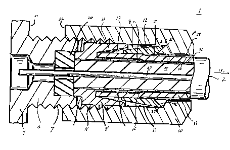
Figure 1 is a partial cross-sectional view of an
embodiment of the present invention used in conjunction with
a termination for terminating a coaxial cable, the
termination in Figure 1 being illustrated in an assembled but
yet to be torqued state; and
Figure 2 is a partial cross-sectional view of the
termination of Figure 1 in its torqued installed state.
Figures 1 and 2 illustrate one preferred embodiment of
the invention wherein the invention is illustrated as part of
a termination 1 for a coaxial cable 2 for terminating and
connecting the coaxial cable 2 to a mounting block 4 having a
mounting nut 6 extending from one end thereof, the nut 6
having external threads 7 thereon. The coaxial cable 2 shown
in Figures 1 and 2 includes inner EMI shield 25, outer EMI
braided shield layer 26, a center conductor 23, an
intermediate dielectric layer 24, and an outer jacket 27.
The termination includes a connector body 8, a driver
member 10 having internal threads 11 engageable with the
external threads 7 of the mounting nut 6, and a compression
member 12. The connector body 8 forms a deformation focusing
portion 13 substantially conical in shape. The portion 13 is
shaped by a substan-
B
1 3n,930r-
MP1085
--4--
tially uniform hollow cylindrical member 14 having a tapered end
15 for facilitating insertion of the cylindrical member 14 bet-
ween coaxial cable braided layer 26 and inner coaxial cable
shield layer 25, as illustrated, and an outer tapered conical
member 16 which surrounds the cylindrical member 14 and provides
therewith a volume of space 13 which increases in an axial direc-
tion indicated by arrow 18, an inner surface of the member 16
having the conical shape. A washer 20 provides sealing against
environmental leakage occurring between threads 7, 11, this func-
tional alternatively being accomplished by a resilient seal 19
disposed across joint 22 between first and second confronting end
walls 21, 22 of the mounting nut 6 and driver member 10, respec-
tively (Figure 2). Though both the seal 19 and washer 20 are
illustrated in Figure 2, if desired only one of these elements
can be chosen.
The torque indicator will now be described by example with
reference to the compression member 12. The compression member 12
includes an outer surface 9 which is substantially conically
shaped and is adapted to be received within the cavity 13. The
compression member 12 further includec an indicator portion 28
which is disposed between the cable 2, specifically its jacket
28, and the driver member 10. Clearances between the indicator
portion 28 and the jacket 27 and member 28 have been exaggerated
in the Figures for ease of illustration. The compression member
12 further includes a collapsible portion 30 having a profile
such that when exposed to a predetermined critical pressure, the
portion 30 deforms and collapses rather rapidly in the axial
direction. In the embodiment illustrated, the portion 30 has a
conical shape, being substantially triangular in cross-section,
such that material can flow into void 31 defined by the portion
30, indicator portion 28, and compression surface 34 of the
driver member 10.
1 3~9305
MP1085
--5--
The compression member 12 is made of a material (e.g.
plastic) which is softer than a material from which the driver
member 10 and the connector body 8 are made (e.g. metal), and
hence when the compression member 12 is pressurized between the
driver member 10 and the connector body 8, the compression member
12 deforms rather than the connector body 8 or the driver member
10. The primary function of the compression member 12 is to pro-
vide a seal between the cable jacket 27 and the driver member 10,
when focused and compressed as illustrated in Figure 2.
Since an angle of slant of an inner conical surface 32 of the
collapsible portion 30 is opposite that of an angle of slant of
the compression 34 of the driver member 10, when the collapsible
portion 30 collapses, to a first approximation, the compression
member 12 moves relative to the indicator portion 28 by distance
A, as visually illustrated by comparing Figures 1 and 2.
The use and operation of the invention will be more specifi-
cally described by reference to the changes in states between
Figures l and 2, with Figure 1 showing an assembled but yet to be
completely installed state of the termination 1, with Figure 2
~howing the completely installed state of the termination 1. In
Figure 1, it can be seen that the driver member 10 has been
threaded around the nut 6 rather loosely such that the
compression surface 34 is in initial contact with the compression
surface 32 of the collapsible portion 30. By turning the driver
member 10 around the nut 6, movement of the driver member 10
axially in a direction opposite the arrow 18 is effected which
causes the compression member 12 to similarly move axially in a
direction opposite that of the arrow 18. The axial movement of
the compression member 12 continues until it lands within the
cavity 13 at which time further movement of the driver member 10
1 3~93~5 MP1085
--6--
causes portions of the compression member 12 to deform until
substantially all voids within the deformation focusing cavity 13
have been filled and the cable jacket 27 has been placed under a
predetermined pressure. Up to this point, minimal relative move-
ment between the driver member 10 and the indicator portion 28
occurs since the collapsible portion 30 of the compression member
12 has only been slightly deformed due to the pressure exerted by
the driver member 10, but has not yet collapsed. Further
tightening of the driver member 10 around the thread 7 of the nut
6 further increases the pressure on the compression member 12 up
to a point where the collapsible portion 30 collapses rather
rapidly which causes the compression member to move in the direc-
tion of the arrow 18 and relative to the driving member 10 the
predetermined distance A. At this time, the craftsman observes
the exposed portion 36 of the indicator portion 28 around the
cable 2 and discontinues turning the driver member 10 around the
nut 6.
By appropriately choosing the material formulation of the
compression member 12, and specifically the collapsible portion
30 thereof, it is possible to precisely control the pressure
which is required to crush the collapsible portion 30 and achieve
the desired movement of the indicator portion relative to the
driving member, with the result that the indicator portion 28
essentially "pops out" of the backend of the termination when
this predetermined pressure has been exceeded. Hence, by choosing
this predetermined pressure to be within a range of optimum
pressures for use in installing the termination 1 such that the
compression member 12 is adequately deformed to seal against all
leakage paths coming from an end of the coaxial cable, and such
that the washer 20 if used also is sufficiently compressed, it
can readily be seen that an easy, efficient, and very reliable
1 3'~q305 MP1085
--7--
means is provided for informing a craftsman when an optimum
amount of pressure has been exerted onto internal parts of the
termination 1, which internal parts are generally hidden from
view from the craftsman. One experiment done resulted in collap-
sible at 600 lb/in2, and an excellent connection resulted.
Though the invention has been described with reference to one
preferred embodiment thereof for use with a termination for ter-
minating a coaxial cable, it can readily be seen that the inven-
tion is useable with many other types of terminations and
connectors wherein it is desired to determine when a predeter-
mined pressure has been exerted on internal parts of the ter-
mination or connector, and accordingly the invention i3 not
intended to be limited to only the embodiment described above,
and is to be limited only by the appended claims.