Note: Descriptions are shown in the official language in which they were submitted.
~3~ 79
TAMPER-EVIDENT CAP CONSTRUCTION
This invention relates generally to tamper-evident
closures for containers, and more particularly to clo-
sure constructions of the type which employ breakable
strips or lugs which are intended to rupture in the
event that the container is tampered with, prior to pur-
chase or initial use by the consumer.
Various arrangements have been proposed and pro-
duced, for indicating that a particular container may
have been tampered with.
U. S. Patent No. 3,455,478 issued July 15, 1969 to
M. Fields, and entitled TAMPER-INDICATING CLOSURE, il-
lustrates one approach, which is typical of that em-
ployed by a number of others, namely providing a closure
cap with a collar that is connected to the cap by thin,
frangible webs or bridges which are intended to break
upon removal of the cap. In this patented construction,
the collar has an internal bead which, during assembly,
is forced over a cooperable external bead on the neck of
the container. The collar is thus permanently retained
on the container even after the cap is removed by the
consumer.
A somewhat similar arrangement is shown in U. S.
Patent No. 3,673,761 issued July 4, 1972 to W. Leitz,
and entitled METHOD OF APPLYING PILFER-PROOF CLOSURES,
except in this latter device, instead of employing a
fixed internal bead on the collar, following installa-
tion of the cap and collar, the lower edge portion of
the latter is heated and thereafter rolled over an ex-
ternal bead on the container neck.
-- 1 --
1309379
Many of the dispensers in use today involve two-
part caps, one part normally referred to as a base cap
part or cap body, and being adapted to be permanently
retained on the neck of the container, and the other
part, commonly known as the screw cap part, being ca-
pable of being unscrewed from the base cap part or cap
body. The necessity for employing this type of construc-
tion is that it is often difficult to mold a container
with a relatively complex neck configuration of a type
that could accept certain screw caps directly. As a re-
sult, the neck of the container is provided with a rel-
atively simple configuration, such as a retention bead,
which can cooperate with a mating retention structure on
the base cap part or cap body. The arrangement between
the base cap part and the container is usually such that
a strong and permanent retention is had. This is usually
accomplished by providing suitable cooperable bead struc-
tures as mentioned above, or by screw thread arrange-
ments associated with locking ratchet teeth, etc. In
practically all cases, such a construction discourages
attempts to remove the base cap part or cap body from
the container neck.
Problems have been encountered, however, in pro-
viding a container which would indicate tampering in-
volving attempted removal of a screw cap from the base
cap or cap body. Since the screw cap and cap body are
not capable of being molded as a single piece, espe-
cially where screw threads are involved, the use of
break-away strips has not, to my knowledge, been suc-
cessful. The employment of glues or adhesives is con-
-- 2 --
13(~9;~79
sidered to be too time consuming and messy, as well asnot providing a reliable bond.
The above disadvar.tages and drawbacks of prior tam-
per-evident closure constructions are largely obviated
by the present invention which provides a tamper-evident
cap construction, comprising in combination a cap body
having a discharge opening, a screw cap adapted to be
received on said cap body so as to selectively close off
the discharge opening thereof, a frangible resilient tab
integral with the screw cap and extending outwardly past
the periphery thereof in overlying relation to an exposed
exterior surface of the cap body, said tab being integral
with the cap body by virtue of a common fused juncture
area at the said exposed exterior surface of the body so
as to resist relative turning between the screw cap and
cap body, said tab having a transverse line of weakness
adapted to rupture when a turning force is applied between
said screw cap and cap body, said cap body having an
upstanding projection underlying the tab and biasing
central portions thereof upwardly such that upon rupture
of the tab, a torn end thereof will be upwardly displaced
by the upstanding projection, thereby to indicate to a
potential user that the cap has been tampered with.
Other features and advantages will hereinafter ap-
pear.
In the drawings:
Fig. 1 is a top plan view of the tamper-evident cap
construction, particularly illustrating the frangible
tab associated with the cap body and screw cap, and il-
lustrating a line or portion of weakness on the tab, ad-
jacent its point of attachment to the screw cap.
- 3 -
79
Fig. 2 is a partial vertical section of the cap
construction of Fig. 1, showing in dotted outline, a
torn end of the tab as it would appear, following rup-
ture.
Fig. 3 is a top plan view, similar to Fig. 1, of
the screw cap and cap body, and the tab as it would
appear just prior to the fusing of the outer end thereof
to the exposed exterior surface of the cap body.
Fig. 4 is a fragmentary section taken on line 4--4
of Fig. 3.
Fig. 5 is a top plan view, similar to Fig. 1, of a
modified tamper-evident cap construction, wherein a line
of weakness or weak-section on the tab is nearer the
point of attachment of the tab to the cap body.
Fig. 6 is a side elevation of the construction of
Fig. 5, showing in dotted outline, a torn end of the tab
as it would appear, following rupture.
Fig. 7 is a fragmentary top plan view of the con-
struction of Figs. 5 and 6, showing the tab as it would
appear just prior to the fusing of the outer end thereof
to the exposed exterior surface of the cap body.
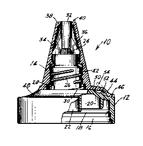
Referring first to Figs. 1-4 there is illustrated a
closure cap construction generally designated by the
numeral 10, comprising a base cap or cap body 12 and a
screw cap 14. Disposed on the inner surface of the body
12 are two annular rings or retention beads 16, 18 which
cooperate with similar structures on the neck of a con-
tainer (not shown), in order to provide a permanent re-
tention of the part 12 thereon. The beads 16 and 18 also
provide a secondary seal between the container and cap
i3(.~379
body 12. The underside of the body 12 has an annular
flange 20 which is receivable in the container neck, and
seals thereagainst. Also a depending duct 22 provides
communication with the discharge passage or opening 24
of the body 12.
The exterior of the body 12 is provided with threads
26 and also a pair of ramps or cam tracks 28, 30 upon
which lugs (not shown) on the underside of the screw cap
14 ride. The arrangement is such that a more positive
unscrewing of the screw cap 14 is made possible by the
provision of the lugs riding on the cam tracks 28 and
30.
~ isposed at the upper portion of the body 12 is a
stopper plug 32 of generally cylindrical configuration,
supported by two legs 34 and 36.
Referring again to ~ig. 2, the screw cap 14 has a
generally conical outer surface configuration, and an
apertured flat top portion 38 with a dispensing aperture
40 that is normally sealed off by the stopper plug 32
when the parts are in the position illustrated. On the
interior wall of the screw cap are threads 42 that en-
gage the threads 26 of the cap body 12. The threads 26
and 42 operate for the most part to urge the screw cap
14 toward its closing position, as shown, whereas the
lugs on the underside of the screw cap and the cam
tracks 28 and 30 operate to force the screw cap open
when it is unscrewed. In the open position, the stopper
plug 32 is removed from the aperture 40, as can be read-
ily understood.
Tamper-evident means are provided on the screw cap
14 and cap body 12, for indicating if the part 14 has
13~379
been disturbed prior to its initial use by the consumer,
said means comprising a frangible tab 44 particularly
illustrated in Figs. 1-4, the tab 44 being molded in-
tegral with the screw cap 14 and being made integral
with the cap body 12 by virtue of a common fused junc-
ture area 46 on the exposed exterior surface 43 of the
cap body 12. As illustrated, this exposed surface 48 is
somewhat conical in shape, having a slight curvature or
concave cross sectional configuration. Also, the tab 44
has a transverse line or section 50 of weakness and is
adapted to tear or rupture along this line when the
screw cap 14 is subjected to a predetermined turning
force, which force may be less than that which would be
required to separate the tab 44 from the fused area 46.
As shown, the tab 44 is elongate and extends radially
outward past the periphery of the screw cap 14, and the
transverse line 50 of weakness is generally perpendic-
ular to the axis of the tab 44.
Fig. 3 shows the assemblage of cap body 12 and
screw cap 14 with the tab 44 prior to the fusing of the
latter to the body 12. The fusing preferably takes the
form of what is known as a sonic weld, wherein heat is
applied to the materials to be fused, by electrical in-
duction. The equipment for accomplishing sonic welding
is known, and accordingly it is not illustrated or de-
scribed.
Further there is provided on the exposed exterior
surface 48 an upstanding projection 52 that is located
beneath the tab 44 and which applies an upward bias
thereto at a location adjacent its center. The tab 44 is
molded integral with the screw cap 14 and has the con-
-- 6 --
~3~
figuration of Fig. 4 prior to assembly. Following as-
sembiy, the tab 44, being resilient, is stretched over
the projection 52 and downwardly onto the periphery of
the surface 48, and the sonic welding is then accom-
plished at location 46. In this manner, there is im-
parted to the tab 44 a cross-sectional configuration
somewhat similar to the capital letter "sn.
Upon the occurrence of tampering, or alternately
during the initial use of the dispenser, the tab 44
ruptures along the line 50, and the torn end 54, shown
dotted in Fig. 2, is propped up by the projection 52,
this constituting a pronounced indication of tampering
to the consumer, more so than would be the case if the
projection 52 were to be omitted.
The particular form of the projection 52 is of no
special significance, except that it is preferably lo-
cated to extend along the area where the tab is ulti-
mately positioned. I have found that by making the pro-
jection 52 arcuate, or semi-circular, the desired result
is achieved, and there occurs little or no interference
with the fusing or welding operation.
A modification is illustrated in Figs. 5-7, wherein
similar reference numerals have been applied to corre-
sponding parts of like construction. The cap body is
indicated 12a, and the screw cap 14a. The tab 44a has a
modified structure in that the line 50a of weakness is
disposed nearer the attachment of the tab 44a to the cap
body 12a than its point of attachment to the screw cap
14a. The internal structures of the cap body 12a and
screw cap 14a of these figures are identical to those of
the first embodiment.
13C~379
In the present instance, the tab 44a would be mold-
ed integral with the screw cap 14a, and initially would
extend straight out from the periphery thereof, as in
Fig. 4. During the fusing operation at the surface area
46a, the tab 44a would again have imparted to it a cross
sectional configuration similar to a flattened letter
"S", as in Fig. 6. In this figure, there is shown in
dotted outline the torn or ruptured end 54a of the tab,
following initial use of the dispenser. The end 54a is
again propped up by the projection 52a on the surface
46a. Fig. 7 illustrates the appearance of the tab 44a
prior to its being fused to the cap body 12a.
From the above it can be seen that I have provided
an improved tamper-evident cap construction which is
both simple in its structure and reliable in operation.
Its simplicity has the advantage that education of the
consumer is not required in order for him to understand
the tamper-evident feature. Moreover, there is no doubt
as to whether or not the tab is intact, because it is
prominent from both above and the side of the container.
The location is such as to immediately draw the atten-
tion of the consumer as he or she is handling the con-
tainer. Thus there is provided a positive indication of
tampering or unauthorized use, thereby protecting the
consumer against possible harm from tainted food, med-
icines or other drugs, etc.
Moreover, high-production techniques can be em-
ployed so that the overall cost is low, and wherein the
additional expense involved with including the tamper-
evident feature is minimal. In addition, the addedplastic material involved with including the tamper-
13~9379
evident feature is extremely low, thus keeping thedevice competitive from the commercial standpoint.
Where the tab is fused to the surface of the cap
body 12, the fusing step can be quickly and economically
carried out with suitable production techniques involv-
ing only minimal time and effort.
The device is thus seen to represent a distinct
advance and improvement in the technology of tamper-
indicating closure constructions.
Each and every one of the appended claims defines a
distinct aspect of the invention which is separate from
all others, and accordingly each claim is to be treated
in this manner when examined in the light of the prior
art devices in any determination of novelty or validity.
Variations and modifications are possible without
departing from the spirit of the claims.