Note: Descriptions are shown in the official language in which they were submitted.
~3094~8
The invention relates to a high-temperature storage battery
having several electrochemical cells disposed in a housing
formed of thermal insulation with inle~ flnd o~tlet openings
for a coolant, preferably air, the coolan~ being conveyed
from at least one inlet opening into an open chamber and
from there through openings in a distributor panel to gaps
between the cells.
Such a battery is known from German Published, Non-Prose-
cuted Application DE-OS 32 47 9~9. That battery has several
electrochemical cells for storing electrical energy. The
battery operates at elevated temperatures, such as in the
temperature range from about 300 to 350C in the case of a
sodium/sulphur battery.
In order to be able to maintain that temperature, high-
efficiency thermal insulation is provided. Heat losses
during idle phases can consequently be kept low. On the
other hand, in the charging or discharging mode heat is
generated due to to the battery effect which results in an
increase in the cell temperature. When an upper cell
temperature is reached, heat has to be removed with the aid
of a cooling system.
Details regarding the construction of a high-temperature
storage battery and the cooling system are to be found in
-3-
13094S8
German Published, Non-Prosecuted Applica~ion DE-OS 32 47 969
mentioned above. It is, in particular, known fr~m the
latter to cover a configuration of several electrochemical
cells with a panel which is provided with holes. The panel
acts as a distributor for a coolant, normally air. A blower
which is necessary for this purpose may be disposed outside
the battery. As may be inferred from Figs. 1 and 3 to 6 and
the accompanying description of the publication mentioned
above, the air is first fed through an inlet opening of the
battery into an upper free space or open chamber above the
perforated panel, from there into gaps between the cells an~
finally to a outlet opening. A number of measures are
specified which are intended to result in a desired distri-
bution of the cooling air. For example, it is proposed
therein to provide the holes in the distribution panel with
different sizes in order to counteract the formation of hot
spots. Finally it may be inferred from the publication that
the distributor panel may also be disposed beneath the cells
instead of above the cells.
It has been found that although the measures already pro-
posed are expedient, they still require improvement in order
to achieve the necessary uniform distribution of the cool-
ant.
--4--
13094S8
It is accordingly an object of the invention to provide a
high-temperature storage battery, which overcomes the
hereinafore-mentioned disadvantages of the heretofore-known
devices of this general type and which further improves the
systems for conveying and distributing the coolant in the
battery.
With the foregoing and other objects in view there is
provided, in accordance with the invention, a high- tempera-
ture storage battery, comprising a housing formed of thermal
insulation with at least one inlet opening formed therein
- for coolant, an antechamber downstream of the at least one
inlet opening in coolant flow direction, a plurality of
throttle locations downstream of the antechamber, an open
chamber downstream of the throttle locations, a distributor
panel having openings formed therein downstream of the open
chamber, and a multiplicity of electrochemical cells mutual-
ly spaced apart in the housing defining gaps therebetween
downstream of the openings in the distributor panel.
In accordance with another feature of the invention, the
antechamber has a wall adjacent the open chamber in the form
of a sheet metal orifice plate having perforations formed
therein defining the throttle locations.
1309458
In accordance with a concomitant feature of the invention,
the antechamber includes a plurality of subsystems intercon-
nected in parallel and/or in series.
The invention provides the advantage of A quasi-~lat inflow
profile in the free space or open chamber transverse to the
main flow direction through the distributor panel, with the
aid of the proposed antechamber. The flow in the free space
or open chamber may be above a distributor panel which is
above the cells according to one embodiment, or below a
distributor panel which is underneath the cells, according
to another embodiment. The profile is achieved regardless
of the velocity of the coolant flow at the inlet opening of
the battery. Without the antechamber according to the
invention, such a flow profile is not established because
the inlet opening has to be as small as possible in order to
minimizing the heat losses while the distributor panel in
the free space or open chamber above or below the cells has
a relatively large area.
Other features which are considered as characteristic for
the invention are set forth in the appended claims.
Although the invention is illustrated and described herein
as embodied in a high-temperature storage battery, it is
nevertheless not intended to be limited to the details
--6--
1309~8
shown, since variouq modifications and structural chan~es
may be made therein without departing from the spirit of the
invention and within the scope and range of equivalents of
the claims.
The construction and method of operation of the invention,
however, together with additional objects and advantages
thereof will be best understood from the following descrip-
tion of specific embodiments when read in connection with
the accompanying drawings, in which:
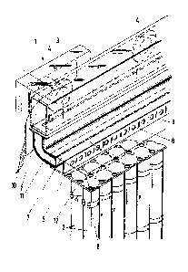
Fig. 1 is a fragmentary, diagrammatic, partly broken-away
perspective view of configuration of cells below a distribu-
tor panel; and
Fig. 2 is a view similar to Fig. 1 showing a configuration
of cells above the distributor panel.
Referring now to the figures of the drawing in detail and
first, particularly, to Fig. 1 thereof, there is seen a
portion of a high-temperature storage battery 1. The
battery 1 contains a configuration of several
electrochemical cells 2 and is surrounded by thermal insula-
tion 3 providing a housing. The thermal insulation 3 isperforated at several locations with passageways in order to
permit battery terminals, measuring conductors and cooling
--7--
~309458
connections to pass through. Such passageways have to be
kept as small as possible and the number of passageways must
be kept to a minimum. For example, preferably only one
inlet opening 4 should therefore be provlded for a coolant,
for example air, and the cross section of the inlet opening
4 should be small. In order to achieve a flow in a free
space or open chamber 5 above a distributor panel 6 which
has a substantially uniform flat flow profile and specifi-
cally which is parallel to the distributor panel 6 despite
the resultant high inflow velocity, an antechamber 7 is
provided in which the coolant builds up and flows through
several throttle locations 8, for example nozzles or holes
in a sheet metal orifice plate 9, into the free space or
open chamber 5. The plate 9 may be considered a wall of the
antechamber 7. In the embodiment used as an example, the
antechamber 7 is formed of a channel 10 which runs trans-
versely to the inlet opening or openings 4 and merges into a
curved compartment 11 and which is closed off by the perfo-
rated orifice plate 9 having the throttle locations 8. The
antechamber (7) may include a plurality of subsystems
interconnected in series and/or in parallel. It is essen-
tial that the coolant flows into the free .space or open
chamber 5 with the same volumetric flow at all of the
throttle locations 8. The path of the coolant from the
inlet opening 4 through the antechamber 7 and the throttle
locations 8 into the free space or open chamber 5 and from
--8--
13~94S~
there throwgh openings or holes 12 in the distributor panel
6 into gaps between the cells 2, is indicated by arrows. In
the gaps between the cells, the coolant absorbs the therrllal
power loss of the adjacent cells and is fed through a
non-illustrated collecting channel to a likewise
non-illustrated outlet opening.
Depending on the chosen battery structure, the illustrated
operating principle can be applied several times through the
use of configurations that are connected in series and/or in
parallel. In addition, the refinements proposed in German
Published, Non-Prosecuted Application DE-OS 32 47 969 can
also be applied in connection with the present invention.
This means, in particular, that the distributor panel 6 may
also be disposed below the cells 2. Such a variation of the
structure of the invention is shown in Fig. 2. In the Fig.
2 embodiment the distributor panel 6 covers the top of the
free space or open chamber 5 and the coolant flows upwards
through the holes 12 in the distributor panel 6 into gaps
between the cells 2.
_9_