Note: Descriptions are shown in the official language in which they were submitted.
13~7~0
1,~11~1,1)1)1,1) I RACK ASSI,M131,Y
round of the Invelltion
_
111is inve11tio11 pertains to the art Or railway
track assemblies an~ 1nore particularly, to embedded
railway track co11structions.
Ihe invention is particu1clrly applicable to a
mass transit railway construction in wl1ich it is
necessary to elnbecl tlle track so tllat it does not extend
substantially above tlle finish grade of the surrounding
ground surface or pavement. Althoug1~ t1~e inve1ltio11 will
be describec1 Witl1 particular reference to an embedded
~, railway construction, it will be appreciate(1 tllat the
inventio11 has broader applications anc1 may be
advantageously employed in still ot1~er rail enviro11ments
and applications.
Mass transit railway constroctions typically
2~ employ a pair of steel rails supported on plural,
perpenc1icularly disl)osed concrete ties. A resilient anc1
insulating rubber pad is interposed between the bottom
flange portio11 of the generally I-shapec1 rails and the
concrete ties. I`hese rubber pads not only electrically
insulate the rail from tlle concrete ties but provicle
vertical resilience Eor the rail. I`he rubber pads
acllieve a predetermined degree of noise and vibration
attenuat iOIl .
D~e to the crowdecl conditions and limited area
available for mass transit tracks, it l1as become
increasi11gly desirable to locate the track in tlle met1ian
strip of a right of way for road traffic. Ideally, this
track must also be adapted to permit emerge11cy vehicles
to not only cross the track Erom one side to the otller,
,. ~
~,,,,,~,...
7 ~ ~
-2-
i. e., in a trallsverse path along the general direction
of tlle cross ties, but must also be able to adequately
support the emergency vellicles fo~ travel in the
longitudillal ~irection, i. e., p~rallel to the rail
direction. Since the rail must accommodate emergency
vehicles along its longitudillal path, the track rails
must be buriecl or embedded to prevent substantial
interference with driving thereon.
Another important consideration is tllat the
'O embedded rail constructions be electrically insulated
~rom the surrounding ground. lhis particularly limits
tlle types of materials that may be used. l`he embedded
track assembly must also be able to withstand
predetermillecl bearing load tests. Additionally, inserts
or filler suppoIt structures contenlplated for insulating
along opposite sides of the rails must be able to comply
with minimum deflection requirements. Once again, this
particularly limits the type of materials that may be
used. Also, the rail must have a positive water seal so
that moisture will not collect and cause environmental
failures.
In ad~ition to being cost effective and easy to
install, the proposecl inserts must also be able to
receive conventiollal rail clips tl~at are spaced at
predetermilled areas along the lengtll of the rails.
Thus, some type of cavity must be provicled in the
inserts at these predetermined areas. Simultaneously,
the inserts must be able to sul)port the required bearing
loads and still meet the minimum deflection requirements
at these rail clip areas.
Convelltional constructions do not contemplate
embedding the rail construction along its entire
longitudillal length. Instead, the rails and a portion
of the support ties are exposed above tlle ground
surface. Only preselected road crossings need be
incorporated into these systems.
,~ ~
-3-
Altllough many railroad crossing structures are
knowll in tlle art, for example, U. S. Patent Nos.
~,36~,845 issued to ~erry, et al. on January 18, 198~;
4,421,272 issued to WJIitlock on ~ecember 20, lg83; and,
c 4,445,64~ issue~ to Caillet on May 1, 1984, tllese types
of structures are limited in their use because of the
higll expense illvolved in tlle structures. Further, none
of these patents are directed to embedding the entire
track construction along its longituclillal lengtll in
lG order to permit not only a transverse crossing of the
railways but longitudinal travel by emergency vehicles
or other autolllotive vehicles. Tlle present inventioll
contemplates a new an(l improved embedded track assembly
tllat overcomes all of tlle above referred to problems and
otllers and provides a lightweigllt, dural)le, alld
economical strs~cture tailored for use in mass transit
railway constructions.
Summary of the Invention
According to the present inventioll, there is
provide(l an insert extencling along the longitudinal
length of the parallel rails for electrically insulating
the rails from the surroslnding groun(l surface and
provides support with limited deflection to accommodate
vehicles in either a transverse or longitudinal
directioll .
According to a more limited aspect of the
invelltion, the inserts include a generally rigid channel
defining an open cavity. An elastomeric member is
supported along an upper face of the rigid chanllel to
provide a resilient nature to the insert.
l .,,
~3~7~0
-4-
According to a first embodiment of the
invention, the rigid member is of metallic construction
that is entirely insulated along any area adjacent tlle
associatecl rail.
~ ccording to an alternate embodiment of the
invention, tlle rigi~ member is o~ polymeric construction
wl~ich is itself an electrical insulator.
According to a still further aspect of tlle
invention, a bonding component is used for sealingly
interconnecting the rigid member with the elastomeric
member.
A principal advantage of the inventioll resides
in tl)e dural)le structure adapted for transverse and
longitudillal vellicle travel.
1~ ~nother advalltage is found in the lightweight
constructioll that facilitates installation.
Yet anotller advantage is realized by the
electrical ins-llating properties of the assembly.
Still other advantages and benefits will become
apparellt to those skilled in the art upon a reading and
understanding of the following detailed description.
~rief DescriPtioll of the Dra~ings
2~
I`he inventioll may take physical form in certain
parts and arrangemellts of parts, preferred and alternate
embodiments of wllicll will be described in detail in this
specification and illustrated in the accompanying
drawings which form a part hereof and wherein:
~ l~UI~B 1 is a perspective view of an embedded
track assembly at a grade crossing according to the
subject invention;
~`
*~
~3()~7~
-- 5 --
FIGUI~E 2 is a vertical cross-sectional view Of
the railway track construction ~enerally along the lines
2-2 of ~ JI~
~ IGUR~ 3 is an enlarge(l, perspective view ~ a
~referre~ insert assembly partially broken away to
facilitate illustration of tlle various components;
IlGUI~ 4 is an enlarged, cross-sectional view
of a first preferred enlbodiment of the subject
invelltion; and,
llGUR~i 5 is an enlarged, cross-sectional view
of a second preferred embodiment.
~etailed Description of the Preferred ~mbodiment
1~
Rererrillg now to tlle drawillgs wl~erein the
sllowings are for purl-oses of illustrating tlle preferred
and a1ternate embodilllellts of tlle inventioll on1y and not
for purposes of limiting same, tlle ~IGUR~S show an
2~ embed(led railwcly track construction A that electrically
insulates tlle rails from tlle surroull(litlg groulld surEace.
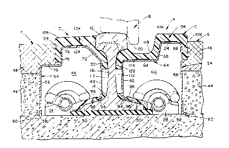
More particularly, the embedded track
constructioll A includes first and second rails 10, 12
eacll havillg a generally I-sllaped cross-section for
2~ supporting an associated wheel l3 of a rail car (not
shown). ~ach rail includes an enlarged support flange
14, top flange 16, and a web 18 interconnecting the top
and bottom flanges.
I`ypically, the bottom flange 14 is operatively
3~ supported along spaced support ties 24. Modern day
constructions utilize concrete support ties and employ a
rubber insulating pad 26 between the concrete ties and
thc rails, altllougll other supl-ort arrangemcnts can be
used without departing from the scope and intent of the
``-6-
subject inventioll. Io firmly retain the rails on the
concrete ties, conventional rail clips 28 are secure~ to
the ties and extend up and over the bottom support
flange 14 to clamp the rails. An insulator 30, sucll as
a glass-filled nyloll melllber is disposed betwen the rail
clip and the bottom support flange to electrically
insulate the rail from the rail clip and support tie.
As dcscribecl above, most railway constructions
have an open track assembly in whicll the ties are only
partially embed~ed in the ground surface. In this
manner, the rails are fully exposed above the finish
grade. ~s described above and detailed in the noted
patents, it is well known to provide a railroad crossing
structure that permits traversal of the rails along a
1~ path generally l~erpen(licular to the longitudinal
directioll of tlle rails. lllat is, tllese structures are
designed to accommodate automotive traffic in a
direction generally parallel to tllat of tl~e support
ties. Ihese structures, though in widespread use, are
extremely expensive and not adapted for emergency
vehicle travel in a direction generally parallel with
the rails. Still further, these structures are only
designed for use at selected regions where a roa~way
crosses or intersects with that oE a railroad.
According to tlle subject illvcntioll, alld as
illustrated in lIGUI~S 1-3? the embedded track assembly
includes inserts C extendillg in operative engagemellt
witll opposite sides of each rail along its longitudinal
lengtll to entirely insulate tlle rails from tlle
33 surrounclillg groun(l surface D. As will become more
apparent below, tlle inserts also provide bearing support
for emergellcy vehicles and the like that can travel in
tlle direction of the rails. Alternatively, tlle inserts
permit transverse crossing of the railway, for example,
3~ at an intersection witll roadway ~.
~r~
.,; .
. ^?, ;`
7 1 3~7~0
As illustrated in llGUR~S 1 and 2, two sets of
parallel rails 10, 12 are disposed for railway traffic
in two directiolls. Since tlle right-llallcl and left-halld
tracks are o~ identical constructions, like numerals
will be used to identiry like elements. A crushed rock
subgrade 36 receives a drainage pipe 38, sucl- as a
perforated polyvinylchloride pipe, in a centralized
drainage recess region 40. A reinforced concrete slab
42 is supported on the crushed stone subgrade and, in
turn, supports conventional concrete ties 24. ~nother
layer Or cruslled rock 44 is disposed on top of the
support ties and an asphalt pavement 46 defines the
finish gr~de.
I`he asphalt pavement is disposed on tl-e outer
or field side ~ of the rails, as well as tlle gauge side
G defined between the irst and second rails 10, 12.
I`l-e devil strip region 48 disposed between adjacent rail
pairs also incorporates the asphalt pavement.
Nevertheless, the compacted stone 44 and asphalt is not
brought into engagemellt with the rails themselves, which
are disposed approximately one illCh l~igller thall the
finisll grade of the asphnlt pavemcnt. ln order to
accommodate this difference in heigllt, an insulator not
only must electrically insulate the rails from the
surroulldillg ground surface ~ but must be able to provide
limited deflection, e.g., one-~uarter inch maximum
deflection, so that an automotive vehicle can travel in
the same longitudinal direction as thAt of the rails
without adverse effect.
The subject new inserts G are designed for
light weight, inexpensive, yet rigid support to provide
limited deflection and electrically insulate the rails
from the ground surface. ~ first preferred embodiment
shown in FIGURB 4 includes a generally rigid member such
~ /, t,~
~3~7~)~
-8-
as an extruded alumillum channel 54. The challnel is of
llollow configuration and has an inverted, generally
U-shaped configoration with a dowllwardly extendillg first
leg 56 that terminates in an enlarged flange 58. Tlle
flange 58 abuttillgly engages the top surface of tllc
support tie an(l is secured tllcreto witll a ram set bolt
60 or other conventional astening means. A second leg
62 is disposed adjacent the rail and operatively engages
the bottom support flange 14 of the rail. Tlle closed
end of the rigid challllel is defined by a transverse
connecting web 64 to substantially close cavity 66
definecl by the rigid channel.
The field side and gauge side challnels have a
slightly different cross-sectional configuration w11icl
is most apparellt in the conllectillg web 64. Ihus, the
differing portions of the connecting web of the field
side F and gauge side G channels are referenced by
separate nulllerals for the sake of clarity. The field
side channel includes a first inclined portion 72 that
23 extends between the vertical sccond leg 62 and a
generally horizolltal planar region 74. Ihe challnel is
oriented so that the second leg is substantially
positioned between the top and bottom flanges 14, 16 of
tlle rail and generally parallel to the interconnecting
web 18 of the rail. Fronl the other end of the planar
region 74 extends a vertical portion 76 that merges into
a second horizontal portion 78. In this n~anner, the
first leg 56 is connected to the second leg to define a
generally inverted U-shaped chanllel.
lhe gauge side channel includes first and
second horizolltal planar regions 84, 86 interconnected
by generally vertically extending portion 88. The first
planar region 84 defines a recessed area to facilitate
receipt of a rail wheel B as will be described further
below.
A. ~
0
- 9 -
An outw~rdly extér,ding leg extension 94 of tlle
s~concl l~g 62 is receivecl in an el~stomeric insulator
96. Ille illsulator 96 llas a generally curvi~ ar
interior face tllat conforms to the arcu.~te merging a~ea
of tlle intercollllectillg web 18 an~ bottom flange 14 of
the rail. Ad~litionallyr clistal end 98 of the insulator
abuttingly engages tlle nylon insula~or 30 associated
with tlle rail clips. I`his abutting engagement between
tlle insulators 30, 96 limits horizontal displacement of
the secon(l leg 62. Of course, one skilled in the art
will realize that tlle conformation of the second leg
might be suitably alterecl to accommodate other rail
fastenillg arrangemellts without departing rom the scope
and intel-t of the invention. In conjunction with the
ram set bolt 6() securing the first leg 56, the entire
rigid challllel is thereby fixedly securecl relative to the
rail and support tie.
rllc second major compollellt of the insert C is
an elastomeric slab or yad member lU4. ~n the field
side 1, tlle elastomeric member has a generally ~lanar
top surface lU6 and a downturllecl regioll 108 that
generally conforllls to the vertical portion 7c'~ of the
rigicl chanllel An interior face 110 of the elastomeric
member closely conforms ancl abuttingly engages the
generally l-sllapecl rail as it necks down from the top
flange 16 to the web 18. rhe interior face, thought
terminates approximately one-third of the way down the
interconnecting web of the rail so that a hollow region
112 is defined between the lower portion of the second
leg 62 and the interconnecting web 18.
Likewise, the gauge side elastomeric member
also includes a generally planar surface region 106 that
exten~s inwar~ly from the downturned portion 108 that
extends along tlle first leg 56. The gauge side
3 ~3 ~ 7 ~ 0
elastomeric member, thougli, inclucles a recess or cut-out
118 tllat closely follows the vertical portion 88 and the
first planar region 84 of the gauge side rigid challnel.
Ihe cut-out 118 freely receives the flange 120 of
associatc~ rail wlleel ~. Similarly, interior face 110
of tlle gauge side elastomeric member also generally
conforms to tlle I-shaped rail but terminates
approximately one-tllir~ of tl~e way down tl~e
interconnecting web 18 to define a cavity 112.
A sealing compound 122 is preferably used
betweell the elastomeric member 104 and tl~e rail. The
compound is designed to eliminate water penetration
througll tlle abutting contact surfaces Or the rail and
elastomeric member. Likewise, a bonding compouncl 124 is
disposecl between the elastomeric member and the
generally rigid cl-anllel at selected regions to attain a
positive bonding relatiotlsllip tllerebetween.
Witll reference now to FIGUI~ 5, an alternate
embodilllellt will be described in detail. Since a
2n substantial portion of the assembly is similar in
construction, like elemellts are idelltified by like
numerals with a primed (') suffix and new elements are
identifiecl by new nulllerals. I`he rigicl chanllcl is
preEerably formed of a clurable insulating higll strength
plastic. It is molded to include generally vertically
extendillg first and second legs 56'ancl G2'
intercollnected by a planar region 84'. The first leg
56' extends upwardly from abutting engagemellt with the
support tie, while the second leg extends upwardly from
abutting engagement with the bottom support flange 14'
of an associated rail. ~n angularly extending leg 126
is inclined inwardly toward the rail from the
intersection of the first leg portion and the planar
region. Ille angular leg deEines an acute angle with
planar region 84' and forms a locking arrangement witl
tlle elastomeric member 104'.
~ '`~'`l
3 3~7~1
'I`lle elastomeric member includes a generally
planar surface 106'. Likewise, the ~auge side has a
recess or cut-out 118'. Once again, tlle cut-out is
designed to receive the ~lange 120' oE an associated
rai~ wl~eel 13'. Since the rigid challnel 54' is of
plastic constructioll the insulator, disposed at the
lower end Or the second leg in the FlGlJII~ 4 embodiment,
is no~ require~. Instead, the secon~ leg direc~ly abuts
the bottom support flange 14' of the rail.
1~ A finger portion 128 is formed in tile
elastomeric mem~er 104' for cooperation with the angular
leg 12~ of tlle rigid plastic channel. The finger
extends dowllwardly and outwardly away from tlle rail and
is lockingly engaged by tlle angular leg of the rigid
13 challllel. More particularly, the asphalt 46' imposes a
vertical downwar(l bearing force componellt on the angular
leg to lock tlle finger in place alld prevent upward
removal oE the elastomeric mellll)er. Additionally, tlle
lateral pressure imposeù by the compacted stone and
23 asphalt retains the entire insert firmly presse(l against
tlle associated rail. Furtller, tlle terminatillg support
flange 58' of the first leg anchors tlle rigid channel
against displacemellt.
A ~air of upwar(lly exten(ling recesses 130, 132
2~ are forme(l in the lower face 134 of the elastomeric
slab. 'I'he first recess 13() facilitates removal of the
entire elastomeric slab in case of repair. l'hat is, if
a lifting force is applied to the elastomeric slab, the
groove 130 will permit the finger 128 to extend inwardly
3~ toward tlle rail an(l be relieved o its locking
engagement witll the angular leg. 'I'he second recess 132
permits adequate deflection when the rail is loaded
under vertical bearing forces and vibratory movements.
In all other aspects, the second embodiment is
3~ substantially similar to that of the first embodiment.
/~ ''
130~7~)0
-lZ-
~ ccorcling to tlle above detailed embodiments,
the following particulars more specifically describe the
typc of materials used:
F I GUR~ 4 ~mbodiment:
~igid channel - Aluminum alloy, metal alloy
~lastomeric menlber - Thermal setting or thermal
plastic
Sealing compoulld - Cohesive elastomeric material
Bonding compound - Cohesive elastomeric material
ElGUI~E 5 Embodiment:
5 l~igid cl-anllel - I`hermal setting or thermal
polymeric material
~lastomeric member - Thermal setting or thermal
plastic
Sealing compoun~ - Cohesive elastomeric material~ ~onding compound - Cohesive elastomeric material
The invention l~as been describe~ with reference
to the preferred and alternate embodilllents. Obviously,
modificatiolls and alterations will occur to others upon
a rcading ancl understalldillg of this specification. For
example, other light weight rigid materials than
aluminulll or plastic can be used with equal success.
Similarly, other compositions can be substituted for the
described elastomer without departing from the scope and
intent of the subject invention. This specification is
intended to include all such modifications and
alterations insofar as they come within the scope of the
appended claims or the equivalents thereof.
"