Note: Descriptions are shown in the official language in which they were submitted.
-- ~ 3 ~
1 B~CKGROUND OF THE INYENTION
3 The present invent;on relates to the pl~cement o~ a three
4 phase ac windings of a coil package into the grooves of an elongated
inductor pertaining to and being the stator of a linear l~otor. This
6 stator is mounted to the underside of a rail plate and carrier so that its
7 grooves face down; the rail plate may pertain to an elongate~ T;shaped
8 carrier or the like, the rail being the cross bar o~ the T. It is moreover
g assumed th~t the winding that comes as a package is compiete at the
point of insertion and includes three physically interconnected bnt
11 electrically insulatell flcxil~le cable.
12
13 Devices, structure and method o~ this kind o~ proce~ure is
14 disclosed in US patent 4,557,038 (see ~lso Cana(lian patent 1,2~4,912)
corresponding to German application 33 23 969 of some of us and
16 others. This known method proposes to bringillg a three cable winding
17 package to the installation site by means of vehicle which e.g~ runs on
18 that T-shaped carrier. The vehicle may be provided at least with one
19 outrig~erlike boom which carries a movable tool arranged to reach
down and below the inductor for forcing the windings of the cable
21 package into the groo7es and putting them into psoper position. The
22 invention improves on this approach.
23
24 Linear motors for electrical tlrives o~ various kinds are well
known in the art. Linear motors include a stator as well as all armature
26 which, eontrary to conventional motors, are not arrang~l on a close(l
27 loop but run basically linear straight with of course the possibility of
28
,
.
1 3 ~ ~ 8 ~ ~
1 slight cu~atures. The electrical energy sllpplied to this motor is
2 converted into mec}lanic~l energy to be imme(li~tely and directly
3 available for transl~tory movement. It is no longer necessary to convert
4 the rotary movement into a linear one whereby certain losses obtain.
6 Line~r motors are usually constructed to have energizing
7 eoils arranged in grooves of a stator and the coil or winding system may
8 be arranged to l)e supplie(:l by a three phase power sllpply system. Tl~e
g armature element is either constructed as a rail, made of an electrically
conductive materi~l such as copper or Al in which c~se one establishes
11 the equivalcnce of asynchrollous motor. Alternatively, the ~rmature is12 made of permanent magnetic material which then provi~les a
13 synchronous motor. Furtller linear motors are knowrl where a coil is
a~ prov;ded in the movable part.
16 Linear motors are used for example as people movers, ~or
17 tr;lnsporting and conveying goods of ~ny kind, for driving moval~le
18 belts, for baggage transportation but also in minlng as feellers for
19 cranes, in drag devices; slides of machine tools are also often operated
as and by Zinear motors; certain mechanic~l gate structures can be
21 moved by line:lr motors of this type. Dependillg on the area of use the
22 motors ~re relatively short or long, wh:ltever the requirements of
23 movement and displ~cenlent.
24
The coils, as stated, are placed in the stator grooves in a
26 conventional manner which aside ~rom the procedure as per the above
227 re~erence is a labor intensive procedure. Obvinusly the longer the stator
~ ~ 3 ~
1 ¦ the more intensive is the labor involved in manufacturing and providing
2 ¦ the entire stator asseml)ly including the placennent of the windings arld
3 ¦ loops into the grooves.
4 l
5 1 Th~ reference merltioned above provides a method and
6 1 equipment by means of which a prefabricatcd arld premanufactllred 3-
7 phase winding package is ~uton~atically placed into the grooves of tlle
statvr or inductor of a linear motor. The winding package is coiled on a
g spool which is mounted on a vehicle and as stated a particular tool that
10 extends from the vehicle takes the package of~ that spool and gradu:llly
11 pushes thc packn~e stcp l)y step illtO thc groovcs of tl~e indllctor or
lZ stator package.
13
14 For this procedure to work it is assumed o~ course that the
stator body is suitably positioned along the path of the vellicle. It is
16 ~urther assumed that the entire range will be covered ultimately by ~
17 drive vehicle under utilization of this kind of linear motor~ It can readily
1~ be seen that this kind of method and the equipment proposed for
19 car~ging out the method e~n place winding p~clcages into the grooves of
a stator assembly of any }ength. Of course the spvol holding the p~ckage
21 has a limited capacity and has to be replaced by a ~esh one every so
22 often. The capLlcib is often (~irly small ~s compared with th~ total
23 length to be accommod:lted so that, relatively speaking, the spool has to
24 be changed rather frequently~
26 It h~s to be consitlered furtiler tllat one cannot just end
27 with one spool and begin with a new one. lRather respective two
' ...... ,.".......... .. ~ .
' -' 1 3 ~
1 packages of windings from th~ difFerent spools have to be
2 interconnected through suit~ble sleeves or the like which of course is a
;~ job to be urldertaken right at the site and constitutes an interl uption of
4 the installation procedure as ~r as placing the loops and windings areconcerrled. 3~unning the dispensing machine of the type above is
6 comparatively simple on account of the automation. On ~he other hand
7 making the through connectiorls and placing the sleeves and so ~orth is
8 a labor intensive procedure requiring highly skilled workmen. There ls a
g certain labor intensity involved which should ~e replaced through other,
more ~utomated procedurc.
11
12
13 DESCRIPTlON OF THE INVENTIO~
14
It is an object o~ the present invention tQ improve the
16 known methods of placing 3-phased windings illto stator grooves for a
17 linear motor using as point of departure the procedure ~s set ~orth in18 the above mentioned patent 4,557,038 or some others~
19
It is a speci~lc object o~ the present invention to provide a
21 new and improved method and procedure for pl~cing 3-phase winding
22 paclc~ge into the grooves of an elongated stator for linear motor which
23 stator is provided with grooves and is mounted facing down from an
24 elongated carrier which is used to ~ccommo~ate a vehicle by means Q~
which and through appropriate tools the windings are placed step by
27 step into the grooves.
-- 1 3 ~
It is ~ feature of the present in~ention to asseml~le a
z winding package from individual cable just pr;or to placement into he
3 grooves of the stator of a linear motor.
In accordance with the preferred embodiment of the present
6 invention the ol)jects and features are attained througll coml)ination o~
7 the following features. At f~lrst individual cal)le are taken from suital)le
8 stores on the vellicle anll run throllgll a l)en(lirlg device that is ~lso
g mounted on the ~ehicle; next the eal)le are meander sh~ped bent and
when in that state the cable are combined with holding structures that
11 are provided at a spacillg corresponding to the spacing of the grooves in
2 the stator; these holtling devices are brought into position Iby means of
13 an ;~ssembly l)elt ~nd they ale spaced thereon at that spacing ~hich
14 corresponds to the groove spacing of the inductor; the holding devices
are subsequently intercollnecte~ througll mechanically strong ribl)ons
6 paid from suitable spools also on the vehicles whereby the winding
7 package and its cable are also secured to the holders at the statesl
8 prede~ermined spacing; finally the thus prepared winding package with
19 attached holding de-~ices are passed to the tool which places ~hem
progressively into the grooves as the vehicle passes along the carrier
21 rail to which the stator is mounted.
22
23 It can thus l~e seen th~t the package of windings prior to
24 being placed in the grooves, is prepare(l in situ by equipment on the
vehicle and not be~ore. ~Ienee the ~ehicle does not stvre windirlg
26 p~ckages l)ut just cable in a suitallle fasllion. The cable are best
27 mollnted on spools or drums and can come in ~hat fashion in vely long
28
., . : . :
` ~3~8~
1 configurations. The 3-phase winding pack~ge is asseml)lc~i 01l tl~e
z vehicle and the thus completed package is not store~ but on a runlling
3 basis placed directly in the grooves of the stator. Hence, winding and
a~ unwinding of a winding package onto and from a spool of limite(l
5 capacity is dispensed with entirely.
~ The package as made in situ ~or being installed
8 immediately, is much longer tharl winding packages that were made~~ln
g the past owing to the very limited capacity in whicll completed packages
10 could be stored, and that, of course, dispenses with the requirement o~
11 frequent interconncction through suitable sleeves or the lih;e. In ~ct it
12 was found that many an asseml~ly can be completed in that fashion
13 withollt any connections l)ut ~t such a length as is usually needed of
feeding current to the system. It can readily be seen that a stator
15 winding system cannot be operated uninterruptedly for indei~lnite iength
16 as ~ar as current feedirlg is concerned~ owing to the linear increase of
17 resistance or the length. It becomes plainly impractic;ll and wasteful no~
8 to feed current to the system in certain spaced intcrv~ls and that length
9 can be matched to the manufactured length so that one has in ~act
20 optimized the procedure. Owing to this featl!re the overall installation
21 becomes more economical and there is the added ad~vantage that the
22 probability of making an assembly error is reduced i~ there are no or
23 just few connections to be made.
24
26 DESCRTPT~ON OF l~lE DI~AWINGS
2B
" , ". . .
IL 3 ~
1 Whilc the specirlcation concludes with claims particularly
2 pointing out and distirlctly claiming tlle slll)ject mattcr which is
3 rcgarded as the invention, it is believed that the invention~ the objects
4 and îeatures of the invention anfl furtller ol)jects, features and
advantages thereof will be better understoo(l from the following
6 description taken in connection with the :lccompanying dr~wings in
8 which:
g Fig. 1 is l~asically a view of a complet~ stator asseml)ly ~or
a linear motor to be made and eorresponds in some degree to Fig. 1 of
11 the aforementionerl patent;
12
13 Fi~. 2 is a schem~tic side view of ~ scction o~ an inductor
14 mountetl on ~ carrier rail witbout having any coil winding or the like;
16 Fig. 3 shows a cross section tllrough the carrier rail shown
17 in Fig. 2 and used in this instance ~s a platform on which an
18 installation vehicle can run in aceordance with the presellt invention~
19
~ig. 4 is a side view o~ the arr~ngcment shown in F}g. 3; and
21
22 Fi~. 5 is a top elevation o~ the devices and equipment shown
23 in Figs. 3 and 4
24
Procee(ling now to the detailed description of the drawings,
26 refcrence numeral 1 rcfcrs to thc pack~ge of winclings which inclu~les227 three cables 2,3,4. The patterning on them is merely shown for reasons
1 3 ~ $ --
1 of facilitating thc identi~cation. Of ~ourse tlle winding stranlls a~
2 cal)le m:ly well be providesl with suit~ble markings in order to avoi(l any
3 mix-up during installation. The cable may be insul~ted but are provided
4 with electrically conductive jackets.
6 Tlle cal)le 2,3,4 are assembled in a coherent paclcage
7 establishing the winding packa.ge 1 alld tlley are sho~Yn in Fig. 1
8 completed for being placed into the grooves 5 of a stator 6 pertaining to
g a line~r motor (Fig. 2). The p~ckage or cal)le assembly incllldes ladder
rung-like cross portions of the meandering cable on whic~a are placed
11 hol(lers S bcing intcrcollnecte(l in p.lrts by Illl!.lllS oï lOOp clelllents 8.
12 For stator constructions generally see also US patcnt 4,31099G6 of one of
13 us.
14
The grooves 5 are in fact closed un(ler utilization o~ the
16 hol~}ing structures 7 such that the windings i.e. the cables 2,3,4 can no
17 longer fall out of the grooves. These structures are aftixed to the c;lble
18 during assembly of the winding p~ckage 1 from the cables 2,3~4.
9 Pre~erably these holding devices 7 are such that through resilient
springing or elastic snap action they can be placed into the grooves. See
21 e.g. the snap action of cvvers 16 in the above mentiolledl patent
22 ~,310,9~6.
23
24 The structures 7 are constructed as semi-shells or the like
having a length correspondillg esselltially to the widtll o~ the stator or
26 inductor 6 and the length of the respect;ve ~rooves 5 therein. As also
27 shown ~n Fig. 1 these covers or holding devices 7 may be combine~l in
28
.~
-- 1 3 ~
1 pairs through loop elements ~. These holding devices 7 are
2 interconnected througll mechanically strong tapes or ril~l)ons 9. These
3 ribbons 9 ;lre af~lxed to tlle axial ends o~ the respective hol~ling
4 structure 7.
6 The ribl)ons or strips 9 make sure that tlle package 1 is
7 firmly held togetl-ler but remains flexil~le. Tlle ribbons run lor the length
8 of the package 1 along both si(les thereof arld on both en(ls of the
g holding devices 7. Fig. 1 sho~rs one of the ril)bons 9 schem~tically as it
runs along one of the ends for the holding devices 7. There is an
ll ad(litioll~l ril)l)on 10 on the othcr sille serving as a grounlling ribl)on; it
2 likewise extends over the entire length of the package 1 ~nd is in good
3 electrical contact with the eonductive jackets of cal)le 2, 3, 4.
14
The inductor 6 i.e. the stator is compriscd of a largc
16 plurality of sheet asseml~lies 11 arranged one bellind another in
7 magnetie contiguity. This inductor i.e. the elements of which it is
8 compose(l is connected to carrier bars or plates 12 I)eing the cross bars
9 of a T-shaped cross section of carrier 13. The carrier 12/13 is made o~
concrete and is hollow for reasons of weight ~s shown in fig, 3. Towers
21 or posts 13a are provided for mounting these carriers 13 along a tracl~
22
23 The stator 6 has its grooves 5 arranged to point down and
24 they are on the underside of the pl~te 12 which is the cross llar of the T.
25 The upper side of tlle plate 12 constitutes a kindl of plat~orm or track oll
226 which e.g. nornlally runs a m:lgnetic~lly hoveling vehicle once t~le
2a
13~$4G
1 linear motor is installed. For the purposes of installation a ve}licle such
2 as 14 m~y also run on th~t platform estal)lislling plate 12.
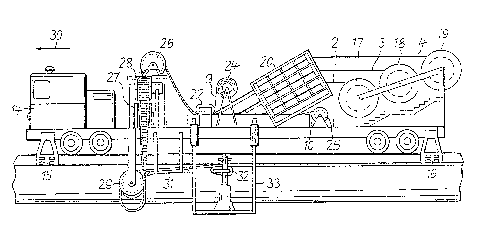
4 Proceeding to further det~ils of the description oP the
vehicle 14 and the method it carries out, one call see that the vehiclc is
6 provided Wit}l gui~le elements 15 and 16 extending beyond the sides of
7 the plate 12 so as to maintain the vehicle on the track platform. 0
8 course there will l)e a more accurate way of running the vebicle in that
g particularly tolcrallccs sucll as 15a will l)c ol)scrvcd throllgllollt the
length of the carricr 13 and plate 12. The sidc e~lges s)f the c~rricr platc
11 12 are actually preciscly ~lcr~llcd SillCe ultimately a high degree of
12 accuracy is neede~l ~or gUi(]illg the magnetic vehicle (not 14) in proper
13 position over an~l along this particular traclc
14
In the present case~ for purposes of installation, magnetic
6 hovering is not used; after all the inductor and stator has not yet
17 completed. The vehicle 14 runs thus on regular wheels an(l is p~ovide~l
18 with its own suitable drive engine be it a gasoline engine or any other
19 Icind. The vehicle carries three spools 17,18 and 19 respectively for the
three cables 2,3,4 which are therefore individually mounted antl made
21 available on that vehicle through the spools. These cables are at this
22 point quite separate from e~ch other and they are provided for being
23 assemblell in a w;nding package, in the course when the vehicle iL4 rurls
24 along the track 12.
26 For purposes o~ assellll)ly, the cal~le 2,3,4 are takcn olF the
28 spools 17,18,19 respectively and are fed to a eable bending structure 20
11
. ' 'l 3 ~
w}licll still keeps these c~l)les sep~rat~ ~nd in wllicll they are
2 individually bent to obtnin ~ me~n(ler sllape. The resulting heads may
3 in addition be crimped on the top or bottom in accordance with the
4 position they will later have (see rcferences al)ove). The bent cable 2,3,4
5 are thell fed to an assembly belt 21 shown in greater details in Fig. 5.
6 This belt has the individual holding elements 7 as showril. The cable
7 2,3~4 as thcy ~rrive in the juxtaposed and stacke(l position have there
8 transverse portions sequentially pressed into the holders 7 by means of
9 a press tool 22 an(l while the belt 21 moves itself and the holding devices
10 7 in the direction of arrow 23. The assembly tool 22 als~ af~lxes the
11 ril)l)ons 9 to thc llol(Jing dcvices 7. Thcsc ril)l)ons arc paid fiom spo()ls12 14. In addition a spool 25 is provide(l to pay out tllc gruurl(ling ribl)on
13 10 whieh likewis~ is aff~lxe~ by means of tlle tool 22 onto tlle winding
14 paclcage 1, to contact on a repetitiYe basis all of the indivi(lual cal)les;
15 since their outer jacket is electric:llly conductive the electrical ground
16 potential is equalized throughout the assembly.
17
18 The arrangement o~ the c~bles 2~3,4 on the spovls 17,18 ~nd
9 19 respectively is the preferred ~orm oï practicing the invention.
20 I~asically there is no essential re~quirement th:lt in f~ct these inllividual21 cables are on spools. Other kind of storage can be providc(l such as coil
22 barrel or the like as long thcy are capablc of storing the requisite length
23 for each of the individual cables and as long as they permit easy
24 withdrawal therel'rom.
2~ The asseml)ly l)elt 21 is pre~erably constructed as an
27 endless belt running through two deflection pulleys. In the alternative it
28
12
.
~ 3 ~
1 may l~e a cllain element also in an en~less configuration. If the endless
2 belt is constructe(l as a ch~in then the in~ivi~ua.l holder 7 can be pl~ced
3 thereon in a ~lxed (listance as giv~n by the chain construction and its
elements. The holders 7 m~y either be placed on the belt by halld or
5 automatically as shown in that they :lre taken ïrom a storage facility
6 and place(l one by one onto tbe asseml)ly belt 21. If that belt runs ~t a
7 constant speed then the regular r~te of dispensing elements est~blishes
8 the predetermined llist~nce an~l spacing wllich then matches the
g distance on the grooves of the linear motor. Suit~ble feedl~ack control
10 may be provided here to ensllre eonsistent accur~cy ~without any
11 accumulation of positional errors.
12
13 In order to pl~ce tlle pack~ge 1 ~ownstream fronl tlle tool
14 22 into the grooves 5 in the inductor 6 a d~flection system is provided to
15 run the assembly down to l)elow tlle cover 12 of carrier 13. This system
16 is comprised of several rollers. Rollers 2~,27,28 and 29 can be seen in
17 Fig. 4. The ~ssembly or p~ckage 1 is ~lrst tak~2l up by (leflection roller
18 ~6, twisted l~y 90 degrees an~l run ~lown via pulleys 28 alld 27 to hallg in
19 a free loop while being tvnsted again and being taken up by pulley 290
21 The placement device gener~lly oper~tes upon moving of the
22 vehicle in the direction of a~row 30 ~nd the l~st roller 2~ runs the
23 winding p~cka~e 1 across tlle support 31 to the placement tool 32. This
24 tool 32 automatically forces the winlling package i.e. ~he windings of the
25 lad~er into the grooves 5 of the in~luctor 6. It is that portion in each
26 instance tllat is l)cing forccll in the grooves which carries the r~spcctive
227 holder 7. Thc tool 32 therefore ïorces the respective c:lble portion ;a~to
:L3
~ 3~3~
1 tlle grooves and presses the holdcrs 7 rcsilicntly into suitablc unllcrcllt
2 portions o~ the grooves ~. Hence the placement of the winding portions
3 in the grooves 5 is simultaneously c~rried out with the af~lxing the
4 position of the winding p~ckages as a whole in the individual grooYes 5
through a~lxing the hol~ler 7 by snap action to the grooves ~nd closing
6 them. In order to compensate any dif~erences in speed the package 1
7 may have a compensating loop in between the rollers 28,29.
8 _
g The support 31 and the tool 32 are provided on at least
outriggerlike boom 33 which extends from and is connected to the
11 vehisle 14. The outrigger boom 33 is adjustal)le as to hcight and12 elevation so tllat it call match to the ex;sting spaci~l conditions. Tllis
13 movability of the outrigger l)oom 33 is p~rticularly important WhCIl t}lf'
14 whole assembly passes through switclles, stations etc
.
16 In a pre~ersed form outrigger boom 33 may be constructed7 to serve simultaneously ~s an assembly platform supporting a person
18 who inspects and monitors the operation on a running basis and
19 monitors particularly the placement o the winding package 1 into the
groovc 5 of the inductor ~. Tllis person may eOg. reach the pl~tl`orm 17y
21 means of a ladder from the interior of the vehicle 14.
22
23 The inventive method is carried out as follows. ~s the
24 vehicle 14 runs on the pl~t~orm track and p}ate 12 cab~e 2,3,4 are
simultancously p~id by and from the spools 17,18 ~nd 19. The~ ~re
26 individually ~ed into the l)ending de~ice 20 whic}l holds thcm above eaeh
27 other and makes them individually into meander pattern. Holding
28
1~ lq
', .. ' . .- ~ .:
.
. .
~3~g~
1 elements 7 are place~l onto the running assembly belt 21. As statcd the
2 hol(ling devices 7 may come in pairs held together by loops 8~ The inter-
3 device spacing of a pair is the same as the spacing from device to device
4 which matclles the spacing of the grooves 5. The belt 21 moves the
s holding devices 7 to the mounting and assembly tool 22. There then
6 arrive also the individual bent cable 2,3,4. The tool 22 now forces the
7 cable one by one a~nd in a cyclically repetitive basis into tlle holders 7 as
8 they arrive one by one on the belt 21. This obtains together and ln
g conjunction witll placement of the grounding ribbon 10 onto and along
0 the cable. In addition the ribbons 9 are attachcd to the holders 7 to
11 thercby interconncct all of the holders 7 which featurc serves as a
lZ further completing the step to obtain a coherent windillg package 1.
13
14 The package 1 is run through the rollers 26 29 to the
15 support 31 and ~rom there into the tool 32 which ~utomatically an~l
16 continuously places the cable portions of the winding package 1 into the
7 grooves S of the inductor 6. It can tllus be seen that asseml)ly of paclcage
8 1 as well as installation of the winding package are carried out on and
9 by the vehicle 14 while that vehicle runs in the direction of arrow 30.
20 The cable dimension such as length is sufficient to provide a w;nding
21 paclcage for one km length without interruption. This one lsm is not a
22 magic number but it was found that it is a vely convenient length along
23 whieh to space the feedlng o~ electric currellt into the windings. For
2D~ longer distances the pass is repeated, possibly with a ncw set of cable
26 spools or one uses large ones to begin with.
27
`
~3~3~-~
1 I~ a new sct of spools are used, the ends of the cal)le can
2 readily be intcrconneeted on the vehicle tllrough known connection or
3 splicing techniques with little or no interruption of the entire proeedllre.
The invention is not iimited to the embodimen.ts described
6 above but all changes and modi~leations thereof9 not constituting
7 departures ~rom the spirit and scope of the invention, are intended to be
included.
22
28 16