Note: Descriptions are shown in the official language in which they were submitted.
~3~01~
POOL ~IMMER
Backqround of the Invention
The present invention is directed toward a pool
skimmer and more particularly toward a simple manually operated
device which can be used to skim and -thereby clean the upper
surface of either an in-ground or above-ground swimming pool.
Those who own or must maintain a swimming pool are
well aware of the problems involved in keeping the same clean,
safe and inviting. Metal objects, stones and other debris
often fall to the bottom of the pool while leaves, insects
and other types of light or more buoyant debris float on the
surface for extended periods. All such unsightly debris, how-
ever, must periodically be cleaned from the pool since it
can become both a safety and health hazard.
Built-in automatic skimmers of swimminy pools are
not very effective in removing the surface debris. Furthermore,
such automatic systems can easily become clogged. Thus r there
remains the need for peri'odically manually cleaning debris
from a pool.
I'he largest majority of pool cleaning devices which
are on the market and have been proposed resemble a fishing
net or the like and include a substantially oval-shaped frame
having netting material suspended therefrom and a handle ex-
tending outwardly from the frame. Such devices are shown,
for example, in U.S. Patent Nos. 3,220,037; 3,368,686; 4,152,
801; 4,198,7~0 and 4,481,117.
While these prior art patents can be used to skim
the top surface of a pool in varying degrees of effectiveness,
` `" 1 3 ~ 7
they are designed and are more useful for picking up specific
objects Erom the bottom of a pool. The shape of the ne-t, the
size of the net opening and the angles at which the handles
extend from the netting frame make it extremely difficult
and time consuming to use these devices to effectively skim
the surface of a pool.
Devices have also been proposed specifically Eor
cleaning or sl~imming only the s~lrface of a swimmin~ pool.
Patent Nos. 4,053,412 and 4,089,074, for exampIe, show floating
net devices which are intended to be positioned adjacent to
the edge of a pool to collect debris from the surface water
as it passes through the net. However, these nets are rela-
tively small and are located in bnly one location. The im-
probable assumption is made that all of the surface water
will pass through the net. This simply does not occur, and
the limited skimming capability is completely lost when the
pool water pump is not operating. Pool pumps are seldom op-
erated more than 8 to 10 hours per day. Cleaning of the debris
from the nets is very awkward and time consuming.
The pool skimming net shown in Patent 4,3G9,109
is somewhat larger than previously described devices and is
rectangular in shape so as to cover a larger area of the pool
surface. However, this device is intended to be rigidly fixed
to the side edge of an in-ground pool and, again, can only
clean all of the surface water if it all passes through the
netting. Again, highly improbable. Furthermore, if the direc-
tion of water flow should change for any reason such as shutting
off the pool pump, any debris which had collected on one side
of the net would be dislodged therefrom and would simply fall
back into the water. Cleaning of the net would be time-consum-
ing primarily due to the need of unfastening it from the mount-
:~ 3 ~
ing bracket. The permanently mounted bracket would also presenta hazard to bathe~s when the net is not used.
The device shown in Patent 4,557,001 is also spe-
cifically designed to clean debris from the surface of a pool.
This device is comprised of an elonga-ted flexible floating
net which is fixed to the pool at one end. With the use of
an elongated handle, the other end of the flexible net is
maneuvered around the pool so that debris is collected in
the loop formed by the device. While, in principle, it would
appear that this device could easily and quickly clean debris
from the surface of a pool, the device is approximately 20
to 40 feet long. Thus, once the debris is collected, it is
almost impossible to withdraw the device from the w~ter without
losing most of the debris back into the water. Complete clean-
ing of the netting is again awkward and time-consuming. Further-
more, this patented device must be used to clean the entire
pool and cannot reasonably be used to spot clean, i.e. to
clean debris from a limited area.
Summary of the Invention
The present invention is designed to overcome the
deficiencies of the prior art and is particularly useful for
cleaning debris from the surface of a swimming pool. The skim-
ming device of the present invention includes an elongated
rectangular frame having a screen extending within the area
bounded by the frame. A telescoping elongated handle is con-
nected to -the frame and extends in the same p'ane as said
frame but outwardly therefrom. The angle of the handle can
be adjusted to extend upwardly and outwardly from the frame
thereby allowing a person to hold the handle while suspending
~3~ ~37
the device in an in-ground swimminy pool to thereby skim the
sur~ace of the water as he or she walks around the edge o~
the pool. The handle can also be adjusted to extend directly
outwardly from the upper part of the frame so that the handle
can rest, if desired, on the upper edge of an above-ground
pool as the skimming device skims the surface of the water.
In accordance with the invention there is provided,
a skimming device for a swimming pool comprising:
a substantially rectangularly shaped elongated frame
means, said frame means having a major axis and a minor axis
and including upper and lower substantially horizontal spaced
apart elongated frame members and substantially vertically
arranged side frame members extending between and connecting
the ends of said upper and lower members, said frame means
defining and substantially lying within a singe plane;
screen means connected to each of said frame members and
extending throughout the area surrounded by said frame
members, said screen means being relatively taut and
substantially lying within the same plane as said frame means;
elongated substantially rigid handle means extending from
said frame means, said handle means being connected to said
frame means, and lying substantially in the same plane as
said frame means, and
means for adjusting the angle of said handle means
relative to the major axis of said frame means with said
handle means always lying substantially within said plane.
Embodiments of the invention will now be describ d with
reference to the accompanying drawings wherein:
Figure 1 is a perspective view of a s~imming device
embodying the present invention and being shown in use by a person
cleaning the surface of an in-ground swimming pool;
A
131~7
Figure 2 is a perspective view of the device shown
in Figure 1 showing the manner in which the handle thereof
is adjus-tablei
Figure 3 is a partial cross-sectional view of Figure
2;
Figure 4 is a view similar to Figure 2 showing the
handle rearranged so that the device can be used to clean
an above-ground swimming pool, and
Figure 5 is a view similar to Figure 1 showing the
device being used to clean the surface oE an above-ground
swimming pool.
- 4a -
. . s_~
~L 3 ~ 7
Detailed Description of the Preferred Embodim~nt
Referring now to the drawings in detail wherein
like reference numerals have been used throughout the various
figures to designate like elements, there is shown in Figure
1 a pool skimmer constructed in accordance with the principles
of the present invention and designated generally a-t 10. The
pool skimmex 10 is shown being used to clean the surface of
the water 12 in an in-ground swimming pool 1~. The actual
process for cleaning the pool 14 will be described in more
detail hereinafter.
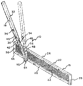
The skimming device 10 is shown more clearly and
in more detail in Figure 2. The device is comprised essentially
of two major parts: a skimmer 16 and a handle 18. The skimmer
16 includes a substantially rectangularly shaped elongated
frame 20 having a screen 22 located within the area bounded
by the frame and secured thereto. As shown in Figure 3, the
screen 22 is preferably relatively taut.
The frame 20 is itself comprised essentially of
an upper substantially elongated and horizontally disposed
frame member 24 and a lower elongated and substantially hori-
zontally disposed frame member 26 which is spaced from the
frame member 20. Vertically arranged side frame members 28
and 30 connect the ends of the upper and lower frame members.
The frame members 24, 26, 28 and 30 are preferably
made of tubular metal and preferably have a substantially
rectangular cross section. The individual frame members may
be separately made and joined together to form the rectangular
frame using substantially any known joining means or it may
be possible to integrally form the frame members into the
desired shape. While other sizes may be possible, it has been
~ 3 ~ 7
found that an overall length of approximately 6 feet and an
overall height of approximately 10 inches for the skimmer
16 best accomplishes the desired results of the invention.
The handle 18 is also preEerably made of tubular
metal having a substantially rectangular cross section. The
handle is elongated and is also preferably made in two parts,
32 and 34, which telescope with respect to each other so that
the length o~ the handle 13 may be changed. Either or both
of the handle portions 32 and 34 may be provided with a plural-
ity of apertures 36 which may be used to adjust the length
of the handle. Once the proper length is selected, the handle
parts are held together through the use of bolt 38 which passes
through the desired apertures and wing nut 40 which secures
the parts together.
Both the upper and lower frame members 24 and 26
are provided with a plurality of apertures such as shown at
42 and 44. These apertures pass entirely through the frame
members and are substantially perpendicular to the plane there-
of. The lower handle portion 34 of the handle 18 is also pro-
vided with a plurality of apertures 46 which pass therethrough.
Bolts 48 and 50 and wing nuts 52 and 5~ are used to secure
the handle 18 to the frame 20.
When the device is intended to be used to clean
an in-ground swimming pool 14, an arrangement such as shown
in Figure 2 is utilized. In this arrangement, the lowermost
end of the handle portion 34 is attached to the lower frame
member 26 through bolt 50 and wing nut 54 utilizing one of
the apertures therein. Although the aperture chosen in Figure
2 is shown to be closer to the left of the frame, it is, in
most cases, desirable to attach the lower end of the handle
closer to the center of the lower frame member 26. The proper
~ ~.
hole 42 on the upper frame member 24 is then aligned with
the proper hole ~6 in the handle 18 so as to provide the proper
desired angle. The bolt 4~ and wing nut 52 then secure the
handle in position.
Although there may be some instances when it is
desired to have the handle extend straigh-t upwardly, it can
be seen from Figure 1 that the most convenient position for
the handle is for the same to extend upwardly and outwardl~
at an acute angle relative to the major axis of the skimmer
16. In this position, a person such as shown at 56 can hold
the handle 18 in a manner similar to the manner in which one
grips a golf club so that the skimmer portion 16 is substantial-
ly horizontal with approximately half of the skimmer lying
beneath the surface of the water and half above the same.
The user can then walk clockwise around the pool usi.ng the
inside edge 58 of the pool as a guide for the vertical frame
member 30 of the skimmer. Since the corners of most pools
are rounded such as shown at 60, the movement around the pool
can be continuous.
After the debris has been collected on the face
of the screen 22, the user merely has to rotate the entire
device upwardly to lift the skimmer portion 16 out of the
water. To remove the debris from the screen, the user simply
turns the screen subs-tantially upside down and taps the lower
frame member 26 (that edge opposite the face where the handle
is connected) on a hard surface. Any debris on the screen
will then simply drop aff.
The dev:ice shown in Figure 4 is identical to that
shown in Figure 2 but with the handle readjusted so that the
same can be used to clean an above-ground pool. This arrangement
is accomplished by simply loosening wing nut 52 and removing
-` ~ 3 ~ 7
bolt 48 and -then pivoting the handle until the same is in
substantial axial alignment with the frame member 26. At this
time, the bolt 48 and wing nu-t 52 are resecured. While the
angle of the handle 18 has been changed in Figure 4 relative
to the axis of the skimmer 16, it can be seen that the handle
continues to lie in substantially the same plane as the frame
just as it did in the embodiment shown in Figure 2. It
should also be noted that the skimmer portion 16 of the device
as shown in Figure 4 has been reoriented. That is, the
lower frame member 26 becomes the upper frame member while
the upper frame member 24 becomes the lower frame member.
Furthermore, it should be readily apparent to those
skilled in the art that the handle shown in Figures 4 and
5 are on the opposite side of the frame. The handle can be
used on either side as desired by simply removing the bolts
48 and 50, moving the handle to the opposite side and rein-
serting the bolts.
The device shown in Figure 4 is particularly useful
for cleaning the surface of an above~ground pool as shown
in Figure 5. With the skimmer 16 lying substantially horizontal
.with approximately half of the screen 22 being above water
and half below the water, ~the handle 18 can rest, if desired,
on the upper edge 62 of the pool. Gripping the handle in a
manner similar to that shown in Figure 1, the user 64 can
then walk around the pool with the vertical frame member 30
again guiding the device around the edge of the pool.
The present invention may be embodied in other spe-
cific forms without departing Erom the spirit or essential
attributes thereof and accordingly reference should be made
to the appended claims rather than to the foregoing specifica-
tion as indicating the scope of the invention.
-8-
,