Language selection

Search

Patent 1310475 Summary

Third-party information liability

Some of the information on this Web page has been provided by external sources. The Government of Canada is not responsible for the accuracy, reliability or currency of the information supplied by external sources. Users wishing to rely upon this information should consult directly with the source of the information. Content provided by external sources is not subject to official languages, privacy and accessibility requirements.

Claims and Abstract availability

Any discrepancies in the text and image of the Claims and Abstract are due to differing posting times. Text of the Claims and Abstract are posted:

  • At the time the application is open to public inspection;
  • At the time of issue of the patent (grant).
(12) Patent: (11) CA 1310475
(21) Application Number: 1310475
(54) English Title: METAL CLAMP
(54) French Title: BRIDE METALLIQUE
Status: Expired and beyond the Period of Reversal
Bibliographic Data
(51) International Patent Classification (IPC):
  • F16L 33/02 (2006.01)
  • F16L 33/035 (2006.01)
(72) Inventors :
  • CALMETTES, LIONEL (France)
  • ANDRE, MICHEL (France)
(73) Owners :
  • ETABLISSEMENTS CAILLAU, SOCIETE A RESPONSABILITE LIMITEE
(71) Applicants :
  • ETABLISSEMENTS CAILLAU, SOCIETE A RESPONSABILITE LIMITEE (France)
(74) Agent: MARKS & CLERK
(74) Associate agent:
(45) Issued: 1992-11-24
(22) Filed Date: 1988-06-14
Availability of licence: N/A
Dedicated to the Public: N/A
(25) Language of filing: English

Patent Cooperation Treaty (PCT): No

(30) Application Priority Data:
Application No. Country/Territory Date
87 08725 (France) 1987-06-22

Abstracts

English Abstract


ABSTRACT OF THE DISCLOSURE
This invention relates to a clamp constituted
by a metal band wound on itself, comprising complemen-
tary tightening and/or joining means in the vicinity
of each of its ends. The band presents, in a zone
preferably remote from said ends, a longitudinal
slit thus defining two band sections, parallel and
contiguous with respect to each other. On each of
said band sections is provided at least one corruga-
tion projecting outwardly of the clamp, each corruga-
tion of one of the band sections being offset circum-
ferentially with respect to each corrugation of the
other band section.


Claims

Note: Claims are shown in the official language in which they were submitted.

THE EMBODIMENTS OF THE INVENTION IN WHICH AN EXCLUSIVE
PROPERTY OR PRIVILEGE IS CLAIMED ARE DEFINED AS FOLLOWS:
1. In a clamp constituted by a metal band wound on itself,
comprising complementary tightening and/or joining means
in the vicinity of each of its ends, the band presenting,
in a zone, a longitudinal slit thus defining two band
sections parallel with respect to each other and being in
contact at respective longitudinal edges formed by the
slit, and, on each of said band sections there being
provided at least one corrugation projecting outwardly of
the clamp, each corrugation of one of the band sections
being offset circumferentially with respect to each
corrugation of the other band section, the metal band
having a constant width over its entire length.
2. A clamp according to Claim 1 wherein said zone is
remote from said ends.
3. A clamp according to either of Claims 1 or 2 wherein
said two band sections are obtained by means of a single
longitudinal slit and thus are contiguous with each other.

Description

Note: Descriptions are shown in the official language in which they were submitted.


1 31 0475
--1--
I MPROVED METAL CLAMP
FIELD OF THE INVENTION
The present invention relates to improvements
in or relating to clamps, especially to those forming
the subject matter of Patent US-A~ 4 275 484 or of
Patent US-A- 4 319 385. More particularly, it aims
at providing, on this type of clamp, a reserve of
elasticity intended to compensate the creep of the
flexible hose, particularly made of rubber, on which
the clamp is tightened with a view to ensuring herme-
tic fixation thereof on a rigid pipe.
BACKGROUND OF THE INVENTION
In fact, tightening of a clamp on a flexiblehose causes creeping of the material constituting
it, particularly if said hose is subjected to relative-
ly important variations in temperature. This mayresult in the force of tightening decreasing, due
to a reduction, even slight, of the diameter of the
hose at the spot where the clamp is tightened. Risks
of loss of tightness of the seal are then to be
feared, the consequences of which may be particularly
serious on certain equipment, particularly on auto-
mobile vehicles.
On the other hand, it is sometimes essential
that the use of the clamps in question does not lead
to too considerable efforts on the hose to be tigh-
tened, of which the diameter may vary within certain
limits. It is therefore desirable that the clamps
comprise means for limiting the tightening effort
upon assembly on a flexible hose whose diameter
attains the upper limit of the tolerances admitted.
A solution to the problems which have just
be set forth has already been proposed, particularly
by Patent FR-A-2 470 275, which provides in the band
constituting the clamp, at least one corrugation
extending over the whole width of the band and projec-
~,

1 ~ 1 ()4 /~
ting outwardly.
This corrugation, comhined with a suitable rigidityof the metal con~tituting the clamp, yives the latter,
a~ter assembly and tightening th~reof on a flexible
hose, the capacity to elastically deform its periphery
in the sense of reducing its length, t~us enabling it to
adapt itself to a reduction of the outer periphery o~
the hose whilst conserving a sufficient tightening force
thereon.
In addition, at the moment of assembly, the
corrugation limi~s the tightening ~orce which is exerted
on the periphery of the hose.
However, the solution proposed is not entirely
satisfactory, in particular if it is impossible to place
between the corrugation and the flexible hose to be
tightened a strip of metal ensuring the continuity o~
the tightening e~fort over the whole periphery o~ the
hose.
SUMMARY OF TH~ I~VENTION
It is an object of an aspect of the present
invention to-improve clamps of the type in question
essentially comprising a metal band wound on itself,
whose ends are provided with complementary tightening
and/or joining msans.
According to an aspect of the invention, the band
presents, in a zone preferably remote from its ends and
the tighteninq and/or joining means, a longitudinal slit
thus defining two band sections, parallel and contiguous
with respect to each other. On each of said band

1 31 0~75
2a
sections i5 provided at least one corrugation projecting
outwardly of the clamp, each corrugation of one of the band
sections being offset circumferentially with respect to
each corrugation of the oth~r band section.
Another aspect of this invention is as follows:
In a clamp constituted by a metal band wound on itself,
comprising complementary tightening and/or joining means
in the vicinity of each o~ its ends, the band presenting,
in a zone, a longitudinal slit thus defining two band
sections parallel with respect to each other and being in
contact at respective longtiudinal edges formed by the
slit, and, on each of said band sections there being
provided at least one corrugation projecting outwardly of
the clamp, each corrugation of one of the band sections
being offset circumferentially with respect to each
corrugation of the other band section, the metal band
having a constant width over its entire length.
., ~,, , ~ ,,

1 31 0475
BRIEF DESCRIPTION OF TH~ DRAWINGS
The invention will be more readily understood
on reading the following description with reference
to the accompanying drawings, in which:
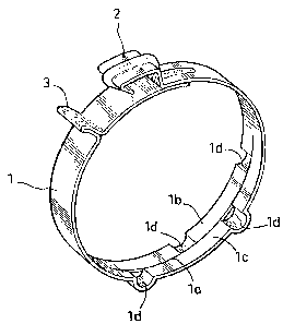
The single Figure shows a view in perspective
of a clamp, improved according to the invention,
in the non-tightened state.
DETAILED DESCRIPTION OF THE DRAWINGS
Referring now to the drawing, it shows a clamp
10 of the type such as the one described in Patent EU-A-0
003 192. It is constituted by a metal band l whose
two ends are provided with complementary tightening
and/or joining means designated by general references
2 and 3.
In a zone remote from the joining means 2
and 3, the band 1 presents a longitudinal slit la
defining two band sections l_ and lc parallel and
contiguous with respect to each other.
However, it is advantageous if the slit lies
20 in the longitudinal axis of the band defining two
sections of the same width and if it is made so that
it does not result in a slot which would risk reducing
the tightening capacity of the clamp.
On each of the band sections l_ and lc is
25 provided at least one corrugation ld; preferably,
and as shown in the drawing, at least two corrugations
will be provided. As may be seen, each corrugation
ld extends over the whole width of the band sections
lb and lc and all the corrugations l_ are preferably
30 identical. However, each corrugation ld of one band
section is offset circumferentially with respect
to all the corrugations l of the other band section.
As is known~ the clamp is tightened by bringing
together the tightening means 2 and 3 and by the
. . , ~...................... ..

1310~75
--4--
hooks that they comprise cooperating.
During this operation, the corrugations ld
are slightly deformed elastically, and are flattened.
If, during use, the material of the tightened
flexible hose begins to creep, the corrugations ld
tend to resume their initial shape visible in the
Figure, thus maintaining the tightening of the hose
at a suitable value.
However, whatever the state of deformation
10 of the corrugations, the continuity of tightening
is maintained on the whole periphery of the flexible
hose thanks to the quincunx arrangement of the corruga-
tions ld of each band section l_ and lc.
In addition, it may be emphasized that the
15 multiplicity of the corrugations ld on each band
section makes it possible to limit their outward
projection whilst conserving a considerable capacity
of extension and, consequently, of retraction of
the band in case of reduction of the diameter of
20 the hose to be tightened under the effect of creep.
Finally, the deformability of the corrugations
allows, as is known, a limitation of the tightening
effort, in the event of the diameter of the flexible
hose attaining the upper limit of the tolerances
admitted. In this way, when the clamp is placed in
position, the appearance of too considerable forces
both on the hose itself and on the tightening and/or
joining members 2 and 3, is thus avoided.

Representative Drawing
A single figure which represents the drawing illustrating the invention.
Administrative Status

2024-08-01:As part of the Next Generation Patents (NGP) transition, the Canadian Patents Database (CPD) now contains a more detailed Event History, which replicates the Event Log of our new back-office solution.

Please note that "Inactive:" events refers to events no longer in use in our new back-office solution.

For a clearer understanding of the status of the application/patent presented on this page, the site Disclaimer , as well as the definitions for Patent , Event History , Maintenance Fee  and Payment History  should be consulted.

Event History

Description Date
Time Limit for Reversal Expired 2008-11-24
Letter Sent 2007-11-26
Inactive: IPC from MCD 2006-03-11
Grant by Issuance 1992-11-24

Abandonment History

There is no abandonment history.

Owners on Record

Note: Records showing the ownership history in alphabetical order.

Current Owners on Record
ETABLISSEMENTS CAILLAU, SOCIETE A RESPONSABILITE LIMITEE
Past Owners on Record
LIONEL CALMETTES
MICHEL ANDRE
Past Owners that do not appear in the "Owners on Record" listing will appear in other documentation within the application.
Documents

To view selected files, please enter reCAPTCHA code :


To view images, click a link in the Document Description column. To download the documents, select one or more checkboxes in the first column and then click the "Download Selected in PDF format (Zip Archive)" or the "Download Selected as Single PDF" button.

List of published and non-published patent-specific documents on the CPD .

If you have any difficulty accessing content, you can call the Client Service Centre at 1-866-997-1936 or send them an e-mail at CIPO Client Service Centre.


Document
Description 
Date
(yyyy-mm-dd) 
Number of pages   Size of Image (KB) 
Cover Page 1993-11-08 1 12
Claims 1993-11-08 1 25
Abstract 1993-11-08 1 16
Drawings 1993-11-08 1 14
Descriptions 1993-11-08 5 159
Representative drawing 2001-07-30 1 11
Maintenance Fee Notice 2008-01-07 1 173
Fees 2003-10-17 1 49
Fees 1999-10-19 1 50
Fees 2004-10-20 1 46
Fees 2005-10-18 1 50
Fees 2006-10-18 1 50
Fees 1995-10-16 1 46
Fees 1996-10-16 1 60
Fees 1994-10-13 1 51