Note: Descriptions are shown in the official language in which they were submitted.
~ ~ 2~ ~
; The present invention relates to a stern tube
seal device.
One of prior art seal devices of this kind
heretofore known has been designed so that a plurality
of lip seals in close contact with and slidable relative
to.the shaft are arranged or mechanical seals are disposed
so as to prevent both leakings, one being leaking of s,ea
water into a machlne (into a ship? and the other being
leaking of lubricating oil ~bearing oil) outside the ship.
~: ~ t
13~ 23~
G9728-6
However, in these prior arts, the seal relies upon the sliding
portion Eormed between the lip seal and the peripheral surface of
the shaft or the sliding portion of the mechanical seal. If
operation is carried out for a long period of time, the sliding
portion tends to be worn or deformed to deteriorate the
performance of the seal, resulting in a danger in that lubricating
oil flows outside the ship to contaminate the sea.
According to a first broad aspect of the present
invention, there is provided a stern tube seal device
characterized in that a plurality of annular case members are
arranged in the outer periphery of a shaf~, an annular recess
portion is provided in the inner peripheral surface of a hole of
said case members, a segment seal member is arranged within said
annular recess portion, a feeding mechanism is provided to feed
pressure gas to said annular recess por-tion closed by said segment
seal member, a lip seal member is arranged at the sea water slde
of said segment seal member, and a mechanical seal, packings or
other float seal member are arranged at the lubricating oil side
thereof.
According to a second broad aspect of the present
invention, there is provided a stern tube seal device for
providing a seal about a rotatable shaft, comprising an annular
casing means disposed about the outer periphery of a rotatable
shaft, a pair of spaced lip seal means mounted in said casing
means and engaging said shaft, said casing means having a recess
intermediate said pair of spaced lip seal means, a resilient ring
seal means disposed in said recess, and pressure fluid feed line
~3,''~
..
~L3123~
69728-6
means feeding pressure fluid to said ring seal means, said ring
seal means comprising a resilient ring member having a hollow
interior, said pressure :Eluid feed line means feeding pressure
fluid to said hollow interior, said ring member having generally
V-shaped portions juxtaposed to said shaft and forming troughs
therebetween, said ring member having passages for passing said
pressure fluid from said hollow interior to said troughs.
According to a third broad aspect of the present
invention, there is provided a stern tube seal device for
providing a seal about a rotatable shaft, comprising an annular
casing means disposed about the outer periphery of a rotatable
shaft, a pair of spaced lip seal means mounted in said casing
means and engaging said shaft, said casing means having a recess
intermediate said pair oE spaced lip seal means, a resilient ring
seal means disposed in said recess, and pressure fluid feed line
means feeding pressure fluid to said ring seal means, said ring
seal means comprising a resilient ring member having a hollow
interior, said resilient ring member having an inner peripheral
portion made of a wear-resistant material.
According to a fourth broad aspect of the present
invention, there is provided a stern tube seal for providing a
seal about a rotatable shaft which extends from the stern tube of
a ship comprising an annular casing means disposed about the outer
periphery of a rotatable shaft, said casing having a recess
extending about said shaft, a resilient ring member disposed in
said recess, said ring member having a hollow interior space, a
Eirst conduit means in said casing means for receiving fluid under
2a
;`;~DI
~3123~
69728-6
pressure from the interior of said ship, said :Eirst conduit means
communicating with said hollow interior space, said ring member
having at least one generally V-shaped portion juxtaposed to said
shaft and forming a trough, said ring member having passage for
passing said pressure fluid from said hollow interior to said
trough, a first and second seal means mounted on said casing means
on opposite sides of said recess, a second conduit means in said
casing means for recovering and returning said fluid to said ship,
said second conduit means having an inlet opening in said casing
means between said recess and said Eirst seal means, said second
seal means having an engaging portion engaging said shaft and a
sloping portion extending from said engaging portion, said sloping
portion sloping radially outwardly as said recess is approached
such that fluid under pressure from said first conduit means
communicates with said second seal means via said outer clearance
space, said passage means and said inner clearance space acting on
said sloping portion of said second seal means to reduce the
pressure with which said engaging portion of said second seal
means engages said shaft to thereby reduce the sliding load
between said second seal means and said shaft.
According to a fifth broad aspect of the present
inventi.on, there is provided a stern tube seal device
characterized in that an annular case member is arranged in the
outer periphery of a shaft, a mechanical seal for sealing a
portion between sàid case member and the peripheral surface of the
: shaft is disposed at a position adjacent to the ship in the inner
periphery of said case me~ber, an annular recess portion is formed
2b
`Yle~^ ~.r~ i
~ 3~2~4~
69728-6
externally o:E the ship and of said mechanical seal in the inner
peripheral surface of said case member, a limited leaking type
seal in sliding relation with the peripheral surface of the shaft
is fitted into said annular recess portion, and a pressure fluid
feed line, which is open to an annular space between said limited
leaking type seal and said mechanical seal, and feeding pressure
fluid to said annular space, is provided.
According to a sixth broad aspect of the present
invention, there is provided a stern tube seal for providing a
seal about a rotatable shaft which extends from the stern tube of
a ship comprising an annular casing means disposed about the outer
periphery of a rotatable shaft, said casing having a recess
ex-tending about said shaft, said recess having an outer radial
recess surface, a floating ring member disposed in said recess,
said floating ring member having an outer radial ring surface and
an inner radial ring surface, sai.d outer radial ring surface being
spaced from said outer radial recess surface to form an outer
clearance space therebetween, said inner radial ring surface being
spaced from said shaft to form an inner clearance space
therebetween, said ring member having passage means extending
between said inner and outer clearance spaces, a first conduit
means in said casing means for receiving fluid under pressure from
the interior of said ship, said first conduit means communicating
with said outer clearance space, a first and second seal mèans
mounted on said casing means on opposite sides of said recess, a
second conduit means in said casing means for recovering and
returning said Eluid to said ship, said second conduit means
2c
~L3~2~
69728-6
having an inlet opening in said casing means between said recess
and said first seal means, said second seal means having an
engaging portion engaging said shaft and a sloping portion
extending from said engaging portion, said sloping portion sloping
radially outwardly as said recess is approached such that fluid
under pressure from said first conduit means communicating with
said second seal means via said outer clearance space, said
passage means, and said inner clearance space acts on said sloping
portion of said second seal means to reduce the pressure with
which said engaging portion of said second seal means engages said
shaft to thereby reduce the sliding load between said second seal
means and said shaft.
~ ccording to a seventh broad aspect of the present
invention, there is provided a stern tube seal for providing a
seal about a rotatable shaft which extends from the stern tube of
a ship comprising an annular casing means disposed about the outer
periphery of a rotatable shaf-t, said casing having a recess
extending about said shaft, said recess having two recess end
faces extending perpendicular to the axis of said shaft and an
outer radial recess surface extending between said two recess end
faces, a floating ring member disposed in said recess, said
floating ring member having two ring end faces extending
perpendicular to the axis of said shaft, each of said ring end
faces being spaced from the respective recess end face to form
lateral clearance spaces between said recess end faces and said
ring end faces, said floating ring member having an outer radial
ring surface and an inner radial ring surface, said outer radial
2d
~ "t ~1 -
~3~23~
69728-6
ring surface being spaced from said outer radia] recess surface to
form an outer clearance space therebetween, said inner radial ring
surface being spaced from said shaft to form an inner clearance
space therebetween, said ring member having passage means
extending between said inner and outer clearance spaces, a first
conduit means in said casing means for receiving -Eluid under
pressure from the interior of said ship, said first conduit means
communicating with said outer clearance space, a first and second
lip seal means mounted on said casing means on opposite sides of
said recess, a second conduit means in said casing means for
recovering and returning said fluid to said ship, said second
conduit means having an inlet opening in said casing means between
said recess and said first lip seal means, each of said first and
second lip seal means having an engaging portion engaging said
shaft and a sloping portion extending from said engaging portion,
said sloping portion sloping radially outwardly as said recess is
approached such that fluid under pressure from said first conduit
means communicating with said second lip seal via said outer
clearance space, said passage means, and said inner clearance
space acts on said sloping portion of said second lip seal means
to reduce the pressure with which said engaging portion of said
second lip seal means engages said shaft to thereby reduce the
sliding load between said second lip seal means and said shaft.
While the present invention has been briefly described,
the present invention and other objects and novel features thereof
will become completely apparent from reading of the following
detailed description in connection with embodiments shown in the
'' i ' '~,1 ~
- 13123~
6972~-6
accompanying drawings. However, the drawings show the embodiments
merely for the purpose of understanding the presen~ invention and
the scope of ~he present invention is not limited thereby. In the
drawings:-
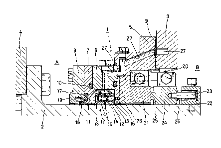
Fig. 1 is a top half of a sectional view of a stern tubeseal devlce in accordance with a first embodiment;
Fig. 2 is a ~op half of a sectional view of a stern tube
seal device in accordance with a second embodiment;
Fig. 3 is a top half of a sectional view of a stern tube
seal devlce in accordance with a third embodiment;
Flg. 4 is a sectional view showing an essential part of
a stern tuhe seal device in accordance with a fourth embodiment;
Fig. 5 is a sectional view cut in half of a
~31234~
stern tube seal device in accordance with a fifth embodiment;
, i ~ Fig. 6 is a sectional view showing an essential
part of a stern tube seal device in accordance with a
sixth embodiment;
Fig. 7 is a sectional view cut in half of a
stern tube seal device in accordance with a seventh
embodiment; and
Figs. 8 through 10 are respectively sectional
views showing an essential part of a stern tube seal
device in accordance with other embodiments.
DESCRIPTION OF PREFERRED EMBODIMENTS
First, a stern tube seal device in accordance
with a first embodiment of the present invention
will now be described with reference to Fig. 1.
The stern tube seal device generally indicated
at 1 seals between a shaft or a sleeve 2 fitted externally
of the shaft and a ship body 3 in which the shaft
is inserted. A reference numeral 4 designates a
part of a propeller mounted on the extreme end of
the shaft.
A reference numeral 5 designates a first
.
case member (casing) fixed to the ship body 3 through ,
; a gasket 9, and a second case member (an intermediate
j ring 6), a third case member (an adapter ring 7)
.
- 4 -
13~ 23~
and a fourth case member (an aft cover 8) are airtightly
mou'n~ed~in said order from the first case member
5 towards sea water A by use of packings 10 or the
like. In these case members 5, 6, 7 and 8 which
are annular in shape, only the second case member
6 has a large diameter hole, said second case member
6 having an annular recess portion 11 formed in the
inner periphery thereof, said annular recess portion
11 having a pair of segment seal members 12 and 12
disposed therein. The segment seal members 12 and
12 are brought into close contact with the outer
periperal surface of the sleeve 2 by fastening forces
of garter springs 13 and 13, the segment seal member
12 at the left side in the figure being brought into
close contact with the end of the third case member
7 by the stretching force of a coiled spring 14
resiliently mounted on the opposed surface between
both the members 12 and 12 whereas the segment seal
member 12 at the right side being brought in~o close
contact with the end of the first case member 5. -
A pin 16 fixed to the first case member 5 is fitted
into holes 15 and 15 coaxially bored in both the
members 12 and 12 to stop rotation of the segment
seal members 12 and 12 with respect to the case member
5.
~ 5 ~
: :
~3~2~
A reference numera]. 17 designates a lip
sea~l mem`ber held and secured between the third and
fourth case members 7 and 8, and an annular lip 18
having a garter spring 19 fastened thereto is brought
into close contact with the outer peripheral surface
of the sleeve 2 against sea water A. A reference
numeral 20 designates a mechanical seal disposed
at the side of lubricating oil B of the segment seal
members 12 and 12, which machanical seal comprises
a slidable ring 21 at the fixed side fitted in the
inner periphery of a shoulder of the first case member
5 and a slidable ring 24 at the rotational side stopped
by a pin 23 with respect to a cover ring 22 fixed
to the sleeve 2 and driven as the shaft rotates to
form a seal sliding surface 25 in a contact surface
between both the slidable rlngs 21 and 24. The`slidable
ring 24 at the rotational side is resiliently biased
towards the slidable ring 21 at the fixed side by
means of a coiled spring 26. A reference numeral
27 designates a preesure gas feeding mechanism in .
communication with the interior of the annular~recess
portion 11 closed by the segment seal members 12
and 12 from the side of the ship body 3, wherein
a pipe line is disposed which extends through the-
first and second case members 5 and 6 from the ship
~12~
body 3, and pressure gas is fed into the annular
rècess portion ll by a feeding device (not shown)
disposed therein. A reference numeral 28 designates
a leaked liquid recovery.mechanism formed separately
from the pressure gas feeding mechanism 27, which
is open to a space between the segment seal member
12 and the mechanical seal 20 to recover the leaked
liquid entered the space into the ship.
As described above, the stern tube seal
device 1 constructed as described above is to prevent
leaking of sea water A into the ship and leaking
of lubricating oil B outside the ship. In general,
the pressure gas feeding mechanism 27 and leaked
liquid recovery mechanism 28 are placed in operation .
during sealing. On the other hand, the lip seal
member 17 and segment seal member 12 serve to prevent
sea water A from leaking-in, and particularly, the
segment seal member 12 is pushed by pressure gas ..
fed into the annular recess portion 11 at the rear
thereof and strongly pressed against the sleeve 2
and case member 7 to enhance the seal effect of the
seal portion. In addition, when pressure of the
pressure gas is increased, the pressure gas passes
~hrough the seal portion and is conversely present
in the space between the lip seal member 17 and segment
.
. - 7 -
~3 ~ 23~
seal member 12 or balanced with sea water pressure
, in said space to display the seal eEfect. Furthermore,
when the space is filled with pressure gas, back
pressure is applied to the lip seal member 17 to
place the lip seal member 17 in an idling state (the
force in close contact with the sleeve 2 disappears)
to prevent early wear, deformation or the like of
.the member 17. In this case, the lip seal member -
17 acts as a dust seal which prevents entry of foreign
matter into the ship, but when pressure of pressure
gas decreases, the lip seal member 17 is pressed
by sea wat:er pressure into close contact with the
sleeve 2 t~o automatically act as a first sea water
resisting seal. Next, for the other lubricating
oil B, the mechanical seal 20 acts as a first seal
portion to;~prevent it from leaking-out, and even
if the lubricating oil B should leak through the
seal portion, leaking of the oil outside the ship
could be c,ompletely cut off by the segment seal 12.
If the lubricating oil B enters the space between
- the mechanical seal 20 and the segment seal portion
12, the oil passes through the seal portion of the
segment seal member 12 and is recovered together
with pressure gas invaded into the space into the
ship by the leaked oil recovery mechanism 28, fo~
: - 8 -
".~ .
,
.. , ~ ' '
13~2~4
reuse. The stern tube seal device constructed as
descri`bed above can completely seal both sea water
A and lubricating oil B in a manner as described
above.
Next, a second embodiment of the present
invention will be described with reference to Flg 2
In Fig. 2, the same reference numerals as those used
in the above-described first embodiment (Fig. 1)
designate the same members. That is, a reference
numeral 2 designates a sleeve, 3 a ship body, 4 a
propeller, 5, 6, 7 and 8 case members, 11 an annular
recess portion, 12 and 12 segment seal members, 17
a lip seal member, 27 a pressure gas feeding mechanism,
and 28 a leaked oil recovery mechanism.
A stern tube seal device 30 having these
members is principally different from the device
shown in the above-described first embodiment in
the following. That is, a fifth case member 31 is
fitted in the inner periphery of a shoulder of the ~
first case member 5, and a~second lip seal member ,
32 is held and secured between both the members 5
and 31. A sixth case member 33 is further fitéed
at the side of lubricating oil B of the fifth case
member 31, and a third segment seal member 34 is
mounted as a float seal member in a space between
~ 3~2~
both the members 31 and 33. The segment seal member
.~ 34 is brought into close contact with the outer
peripheral surface of the sleeve 2 by a garter spring
35 fitted in the outer periphery of the segment seal
member and brought into close contact with the end
' of the fifth case member 31 by a coiled spring 36
'' to be stopped by a pin not shown with respect to
the sixth case member 33. A pipe line of a second
leaked liquid recovery mechanism 37, which is open
to a space between the lip seal member 32 and segment
seal member 34, is provided extending from the fifth
. case member 31 to the first case member 5. The first
and second leaked liquid recovery mechanisms 28 and
37 can provide the junction of pipe lines within
the first case member 5 or ship body 3 to use in :
common of'an intake recovery device such as a pump.
The stern tube seal device 30 constructed
as described above displays similar operation and
effect in seal water A resisting seal to those of
the above-described first embodiment. As for lubricat-
ing oil B, the first seal portion is formed by the
third segment.seal member 34 to assume the extremely
.
reduced state even if lubricating oil leaking through
the seal portion is present, and therefore, sufficient
sealing can be achieved by the lip seal''me'mber 32!! ~
.
- 10 -
'
"
~3~234~
without much difficulty to recover it into the ship
~by the leaked liquid recovery mechanism 37.
Next, a third embodiment will be described
with reference to Fig. 3.
In this figure, a reference numeral 42
designates a shaft (including a sleeve slipped external-
ly on the shaft) to left-hand of which is mounted
a screw not shown. A case member 43 comprising first
to fifth members 44, 45, 46, 47 and 48 is arranged
in the outer periphery of the shaft 42 and fixed
to a ship body 50 through a packing 49. A reference
numeral 51 designates an outer lip seal which is
located in the inner periphery of a hole of~the case
member 43 and held between the first case member
44 and the second case member 45, the outer;lip seal
having a pressure receiving surface 51a, which is
fitted with a fastening ring 52, arranged opposite
sea water A. A back-up ring portion 45a for controlling
operation of the lip seal 51 is provided at the rear
of the second case member 45 with respect to the
; lip seal 51. A reference numeral 53 designa;tes an
inner lip seal held between the fourth case;member
47 and the fifth case member 48, the inner llp seal
having a pressure receiving surface 53a, which is A '
fitted with a fastening ring 54, directed towards
-- 1 1 --
~3~23'~
lubricating oil B which is opposite the outer lip
sea~:Sl.:` A back-up ring portion 47a with respect
to the lip seal 53 is provided in the inner periphery
of the fourth case member 47. The inside diameter
of the third case member 46 among the case member
43 is made greater than that of other four members
44, 45, 47 and 48, particularly the second and fourth
case members 45 and 47, and an annular recess portion
55 is formed in the inner periphery of the third
case member 46, the annular recess portion 55 being
provided therein with a floating ring seal 56. This
floating ring seal 56 is such that a knock-pin 57
projected on the fourth case member 47 engages a
cut 56a formed in one end thereo-f to be stopped with
respect to the case member 43 and both ends and an
inner peripheral surface thereof are slightly distanced
form the ends of the second and fourth case members
45 and 47 and the peripheral surface of the shaft
42 to form fine clearances 58, 59 and 60. The floating
ring seal 56 is formed in its inner perlpheral.surface ,
with an annular groove 56b and provided with the
required number of through-holes 56c which extend
through the inner and outer peripheral surfaces.
A reference numeral 61 designates a feed line of
pressure fluid in communication with the annular
- 12 -
13~23~
recess portion 55 partitioned by the floating ring
seai `56`from the side of the ship body, which line
extends through the third and fourth case members
46and 47to feed pressure fluid into the annular recess
portion 55 from a fluid feed device (not shown) disposed
within the ship. A reference numeral 62 designates
a leaked liquid recovery line formed separately from
the pressure fluid feed line 61, which recovery line
is open to a space between the floating ring seal
56 and the internal lip seal 53 to recover leaked
liquid entered the space into the ship by means of
a pump or the like not shown.
In the stern tube seal device 41 constructed
as described above, when pressure fluid is fed into
the annular recess portion 55 from the pressure fluid
feed line 61, the annular recess portion 55 and annular
groove 56b of the floating ring seal 56 in communication
with the recess portion 55 through the through-hole
56c are filled with pressure fluid, and the pressure
fluid passes through the clearances 58, 59 and 60
and gradually flows into spaces 63 and 64. Among
this pressure fluid, pressure fluid flowing into
the space 63 between the external lip seal 51 and
floating ring seal 56 is stored in the space 63 so
as to act as back pressure with respect to the external
- 13 -
~3123~
lip seal 51 to lower a sliding load between the lip
seal~ 51 and the peripheral surface of the shaft 42
and to prevent entry of sea water. In this case,
it is considered that the pressure fluid might flow
outside the ship~ depending on pressure, and therefore,
it is desireable to select and use pressure fluid
which poses no problem in terms of contamination
of the sea, most preferably, air or the like. On
the other hand, pressure fluid flown into the space
between the internal lip seal 53 and the floating
ring seal 56 is recovered into the ship from the
leaked liquid recovery line 62 together with lubricating
oil B leaked out of the internal lip seal 53, if
any. In this manner, the floating ring seal 56 is
possible to sufficiently perform a function as a
secondary seal with respect to the lip seals 51 and ;
53 as far as pressure fluid is being fed. Even if
feeding of pressure fluid is stopped for some reason,
the floating ring seal 56 functions as a secondary
seal of a limited leaking type to maintain the sealing
effect to some extent in cooperation with the recovery
mechanism by the leaked liquid recovery line 62.
Accordingly, in accordance with the seal device 41
constructed as described above, the external lip
seal 51 is pressed at the rear surface by the pressure
- 14 -
13123ll~
fluid to lower the sliding load between the lip seal
51 and the peri.pheral surface of the shaft 42 to
enhance the durality of the lip seal 51, which has
been heretofore worn materially, to positively seal
both sea water A and lubricating oil B and to recover
the lubricating oil B into the ship through the leaked
liquid recovery line 62, thus removing a fear of
- contamination of the sea. Next, Fig. 4 shows an
essential part of a fourth embodiment. That is,
the floating ring seal 56 comprises a double type
seal 65 whose rear surfaces are opposed. Both seal
: members 66 and 67 are stopped for rotation by a common
.knock-pin 68, and the required number of springs
6g are interposed between both the seal members 66
and 67. ~.
Next, a fifth embodiment of the present
invention will be described with reference to Fig. 5.
In this figure, a reference numeral 72
designates a shaft (including a sleeve slipped external-
ly on the shaft) to left-hand of which is mounted
a screw not shown. A case member 73 comprising first
to fifth members 74, 75, 76, 77 and 78 is arranged
in the outer periphery of the shaft 72 and fixed
to a ship body 80 through a packing 79. A reference
numeral 81 designates an outer lip seal which is
. - 15 -
1~1 23~
located in the inner periphery of the hole of the
case member 73 and held between the first case member
74 and the second case member 75, the outer lip seal
having a pressure receiving surface 81a, which is
fitted with a ~astening ring 82, arranged opposite
sea water A. A back-up ring portion 75a for controlling
operation of the lip seal 81 is provided at the rear
of the second case member 75 with respect to the
lip seal 81. A reference numeral 83 designates an
inner lip seal held between the fourth case member
77 and the flfth case member 78, the inner lip seal
having a pressure receiving surface 83a, which is
fitted with a fastening ring 84, directed towards
lubricating oil B which is opposite the outer lip
seal 81. A back-up ring portion 77a with respect
to the lip seal 83 is provided in the inner periphery
of the fourth case member 77. The inside diameter
of the third case member 76 among the case member
73 is made greater than that of other four members
74, 75, 77 and 78, particularly the second and fourth
case members 75 and 77, and an annular recess portion
85 is formed in the inner periphery of the third
case member 76. A reference numeral 86 designates
a pressure type hollow ring made of rubber fitted
into the annular recess portion 85j the hollow ring:'
- 16 -
~L3~234~
having a plurality (three shown in the figure) of
annular crest portions 86acontinuously provided in
the inner peripheral surface thereof, said crest
portions 86a serving as a seal portion in contact
with the shaft 72, and having the required number
(two shown in the figure) of fine holes 86d bored
to provide communication between a ~rough portion
86b, between the crest portions 86a, and a hollow
portion 86c. A reference numeral 87 designates a
pressure fluid feed line bored from the ship body
side towards the hollow portion 86c of the pressure
hollow ring 86 to feed pressure fluid into the hollow
portion 86c from a fluid inlet device (not shown)
disposed within the ship. A reference numeral 88
designates a leaked liquid recovery line formed
separately from the pressure fluid feed line 87,
which recovery line is open to a space between the
pressureltype hollow ring 86 and the inner lip seal
83 to recover leaked liquid entered the space into
the ship by means of a pump or the like not shown.
In the stern tube seal device 71 constructed
as described above, when pressure fluid is fed into
the hollow portion 86c of the pressure type hollow
rlng 86 from the pressure fluid feed line 87, the
pressure fluid is filled into the hollow portion~
- 17 -
!
~31 ~34~
86c, passes through the fine holes 86d and filled
into a space of a ;~riangular section surrounded by
inclined surfaces of ~he adjacent two crest portions
86a and the peripheral surface of the shaft 72 whereby
pressure is balanced by the space and hollow portion
86c to bring the pressure type hollow ring 86 into
contact with the shaft 72 under the condition of
low load. When pressure fluid is further fed, the
pressure fluid breaks a seal portion between the
pressure type hollow ring 86 and the shaft 72 and
flows into the spaces 89 and 90. Pressure fluid
flown into the space 89 between the outer lip seal
81 and the pressure type hollow ring 86 is stored
in the space 89 to act as back pressure with respect
to the outer lip seal 81, thus lowering the sliding
load between the lip seal 81 and the peripheral surface
of the shaft 72 and prevent entry of sea water A.
In this case, it is considered that the pressure
.
fluid might spread the lip seal 81 and flows outside -
the ship depending on pressure, and therefore, it ;
is desireable to select and use pressure fluid which
.
poses no problem in terms of contamination of the
sea, for example, such as compressed air. On the
other hand, pressure fluid flown into the space 90
between the internal lip seal 83 and the pressure
~ ; '
~ - 18 -
1~23~
type hollow ring 86 is recovered into the ship from
the leaked liquid recovery line 88 together with
lubricating oil B leaked out of the internal lip
seal 83, if any. In this manner, the pressure type
hollow ring 86 is possible to sufficiently perform
a function as a secondary seal with respect to the
lip seals 81 and 83 as far as pressure fluid is being
fed. Even if feeding of pressure fluid is stopped
for some reason, the hollow rlng functions as a
secondary seal of a llmlted leaking type to malntain
the sealing effect to some extent in cooperation
with the function of the leaked llquld recovery line
88. Accordingly, in accordance with the seal device
71 constructed as described above, the external llp
seal 81 is pressed at the rear surface by the pressure
fluid to lower the sliding load between the lip seal
81 and the peripheral surface of the shaft 72 to
enhance the durablity of the lip seal 81, which has
been heretofore worn materially, to positively seal
both sea water A and lubricating oil B and to recover
the lubricating oil B into the ship through the leaked
liquid recovery line 88, thus removing a fear of
contamination of the sea. Next, Flg. 6 shows an
essential;part of a slxth embodiment. That ls, the
inner peripheral portion 86e of the pressure typè `
- 19 -
.
,
~' .
~312~
hollow ring 86 is formed of synthetic rubber or fluoro-
re~in which is~excellent in wear resis~ance to enhance
~ R~p6~
the wear ~e~r~e.
~ - Next, a seventh embodiment of the present
invention will be described with reference to Fig. 7.
In ~ig. 7, the stern tube seal device general-
ly indicated at 101 is mounted in an opening of a
hole of a ship body 103 so as to seal between a sleeve
102 fitted externally of a shaft (not shown) and
a ship body lQ3 in which the shaft is inserted.
A reference numeral 10~ designates a part of a propeller
' mounted on the extreme end of the shaft. In the
stern tube seal deivce 101, a reference numeral 105
designates a first casing fixed to the end of the
ship body 103 through a gasket 106, and on the side
of sea water A of the first casing 105, a second
cas,ing (adapater ring) 107 and a third casing (aft
cover) are airtightly fixed by suitable 0-rings 109
or the like. In the inner peripheral surface of
the second caseing 107, an annular recess portion
llO is formed by t~e second casing 107 and the first
casi~g lOS at the side of the ship, the annular recess
portion 110 having a segement seal 111 as a limited
leaking type seal mounted therein. This segment
seal 111, which are circumferentially divided into
- 20 -
~12~
plural portions, is fastened by a garter spring 112
fitted in the outer periphery thereof and ls slidably
moved in close contact with the peripheral surface
of the sleeve 102 and brought into close contac~ $
with a wall surface 107a of the second casing 107 ~ , -
by a coiled spring 113 disposed at the side of`~ip.
The divided elements of the segement seal 111 are ~ `
stopped to be rotated against the casings 105 a~d
107 by means of pins not shown projected from the
first or second casing 105, 107. A reference numeral
114 designates a lip seal held and secured between~
the second and third casings 107 and 108, the lip .
seal having a pressure receiving surface 114a fast~ened
!; .
by a garter spring 115 directed towards sea water
~, and being slidably moved in close contact with the .
~ ~: outer periphery of the sleeve 102. A back-up ring
: , portion 107b for controlling excessive deformation ~
of the~lip seaI 114 is provided on the back of the .
lip seal 114 of the second casing 107. A reference ~
numeral 116 designates a mechanical seal arranged .
~ :
. ~ at a position closer to lubricating oil B in the
nner periphery of~a~hole of the first casing lOS,;
which seal is fitted in a shoulder of the first casing
105 and maintained.airtight by an 0-ring 118. The
. ~ mechanical seal comprises a sliding ri~g 117 at t~he~ .
21 -
:
1312~
fixed side stopped for rotation against the casing
105 by means of a pin not shown, a cover ring 119
fixed to the sleeve 102 by means of a pin uot shown
and a sliding ring 120 at the rotational side rotated
as the shaft stopped for rotation by means of a pin
not shown rotates. The sliding ring 120 at the
rotational side is pressed by a coiled spring 121
to form a sealed slidtng surface 122 in the surface
in contact with the sliding ring 117 at the fixedi'~
side. A reference numeral 113 designates a pressure
fluid feed line for feeding pressure fluid from the
side of the ship body 103 towards a space 124 of
an annular hole formed between the segment seal 111
and the mechanical seal 116, wherein a p~pe line
open to the spacethrough the first casing 105 from .
the ship body 103 is arranged, and a feed device
not shown is provided within the ship body 103.
The stern tube seal device 101 constructed
as described above is designed to prevent entry of
sea water and~slurry contained ln sea water into
the~mechanical seal 116 by the llp seal 114 arraneed
externally of the mechanical seal 116 (on the s~ea
water side), the segment seal 111 and the pressu~e
fluid. It is noted;that durine sealing, as a rule,
the feed device is actuated to feed pressure fluid.
: : ~
~ 22 -
.
'
:
~31234~
That is, Eirst, the lip seal 114 and segment seal
l~ll serve to p~event entry of sea water A, and
particularly, the segmen-t seal 111 is pressed against
the peripheral surface oE the sleeve 102 and the
wall surface 107a of the second casing 107 to enhance
the sealing effect. When pressure of pressure fluid
exceeds a certain level with respect to the segment
seal 111 which is of a limited leaking type, the
pressure fluid flows towards the lip seal 114 conversely
but the pressure fluid is also balanced with sea
water pressure to exhibit the sealing effect. When
the space between the lip~seal 114 and segment seal
111 is filled with pressure fluid, back pressure
is applied to the lip seal 114 by the pressure fluid
. , .
to place the lip seal 114 in an idling state balanced
with sea wa-er pressure thereby preventing early
wear, de~formation or the like due to the sliding
contact between the lip seal 114 and sleeve 102.
.
The lip seal 114 also acts as a dust seal which prevents
entry of foreign matter into the ship, but when pre6sure`
:, :
of pressure fluid a-t the rear decreases for some
reason, the~lip seal is pressed by sea water pressure
into close contact with the sleeve 102 to automatically
act as a first sea water resisting seal. It is noted
~ that the pre66Ure fluid mlght spread the llp seal
; - 23 -
,
::
~ .
13~23~
114 depending on pressure and Elows outside the ship,
and~therefore, air, nitrogen gas, clean water or
the like which involves no problem such as public
hazards even if the fluid leaks into sea water are
desirable for use. On the other hand, lubricating
oil B can be completely sealed by the mechanical
seal 116 which has been increased in durable sealing
properties by the above-described structure.
~ ext, Figs. 8 to 10 show modified embodiments
of the present invention in which in place of a~segment
seal of a limited leaking type seal described in
the previous embodiment, an integral type (which
is not divided peripherally) floating ring seal 125
(Fig. 8), anend type rubber seal 127 (Fig. 9) or
a hollow type pressure ring 130 (Fig. 10) is used.
That is, a floating ~ing seal 125 shown in Fig. 8
is s-topped for rotation by means of a pin (not shown)
mounted on the first or second casing 105, 107 and
pressed by a coiled spring 126 in contact with the
wall surface 107a of the second casing 107 and has
a fine clearance relative to the peripheral surface
of the sleeve 102 to seal pressure fluid in a!manner
of limited leaking type. ~n end type rubber seal
127 shown in Fig. 9 is slipped over the sleeve 102
by a garter spring 128 to form a sealed sliding surface
~ - 24 -
~3~23~ -
relative to the wall surface 107a of the second casing
1'07`to seal fluid by said surface. A flushing line
129 is open to an annular groove 127a formed in said
surface from the second casing 107. This flushing
line is branched from the pressure fluid feed llne
123, and clean water is used as a feed fluid to thereby
provide lubrication for the sliding surface. A hollow
type pressure ring 130 shown in Fig. 10 is mounted
in close contact with the first and second casings
105 and 107 as if filled in the annuar recess portion
110, and is branched from the pressure fluid feed
line 123 relative to the hollow portion 130a or
fed with pressure air fro~ a line 131 separately
provided so that it is e~panded in a direction of
inside diameter to come into close slidable contact
with ~he peripheral surface of the sleeve 102. Use ~ `
of the pressure type hollow rlng 130 enables to vary~
the state oI close contact wit`h the peripheral surface
of the sleeve 102 by controIllng a feed amount of
the pressur~e alr to adjust a leaking amount of the
pressure fluld. ~n~inner~peripheral surface portion
;;of the hollow ring~130, whlch is normally formed~
of synthetic rubber or the like, can be formed of
a sliding material such as fluororesin to thereby~
enhance th~e~wear reslstance.;
:, : ~ . :
~ 25 -
'~ ~ ' ' ''.'
~ 3~2~
In the stern tube seal device oE the present
invention, ~enerally, a segment seal member, a lip
seal member, a mechanical seal and the like constltute
a multiple stage seal portion, and pressure of pressure
fluid is utili~ed, as described above. Therefore,
not only the excellent sealing performance with~respect
to both sea water and lubricating oil is displayed
but also the lip seal or the like arranged closer
to sea water can be relieved in burden by the pressure
of pressure fluid or to prevent damages given to
a mechanical seal, thus enhancing the long-period
durability of the whole device. ~oreover, according
to the stern tube seal device of the present invention,
contamination of the sea can be prevented to effectively
cope with various problems ln contamination which
has been recently raised as an international problem.
While the preferred embodiments of the ~ ;
present invention have been described, it will be
apparent that the present invention can be variously;~
modified without departing the princlple thereof.
It is therefore desired that all the modifications,
by~which the ef~ects of the present invention~are
obtained substant~ially through the use of substantially
identical or corresponding structures, are included ~
in the category of the present invention by the appended
clalms. ~ ~ -
26 - -
: : ,
:
. ~' ' ~
,
.