Note: Descriptions are shown in the official language in which they were submitted.
~3~236~
SENSII'IVE FAULT DETECTION SYSTEM FOR
PARALLEL COII. AIR CORE REACTORS
- Field of Invention
This invention relates to an improved air core
reactor and improvements in protection schemes for detecting
faults in air core reactors and in particular for air
core reactors which consist of a large number of coaxial
coil windings electrically connected in parallel. The
invention is particularly directed to a method of detecting
electrical faults in air core reactors and to the construction
of air core reactors which permits carrying out such method.
The detection of faults of the present invention is applicable
to single-phase reactors having more than one paralleled
layer and to 3-phase banks of such reactors and to 3-phase
VAR reactor banks. Although the protection scheme is
most effective with reactors in which all layers are wound
2-high (or n-high where n is an even integer), it can
also be used for protecting l-high~reactor3s, but with
a reduced sensitivity.
The size of air core reactors used on large
power systems has grown steadily and it is quite common
today to use reactors rated 50 MVA and larger. In addition,
these reactors are often employed in conjunction with
other apparatus such as ~or VAR control, where a serious
fault in the reactor can allow excessive rate of change
of current through the thyristors resulting in serious
damage to the expensive solid state components of the
system. It is therefore very important to be able to
identify faults in reactors at an early stage and to take
-- 1 --
~ r
13123~
appropriate actions beEore either the reactor or other
componen-ts in the system are damaged.
The problem is especially difficult for multi-layer
paralleled coil reactors where the initial fault may be
so small that it cannot be detected by conventional means.
The system proposed herein has the following advantages
over existing systems: (1) it can detect faults in the
finished reactor before it leaves the factory which would
be undetectable otherwise; (2) it is able to detect initial
faults in reactors in the field long before other protection
schemes could detect them and thus to allow appropriate
actions to be taken to prevent serious damage to the coil
and to other connected equipment; (3) the new fault detection
system also makes it very simple to diagnose the problem
in the field and to establish exactly where the fault
has occurred. This may allow repairs to be made in the
field and if not, allows the unit to be shipped back to
the factory to be repaired at minimum cost.
Background of the Invention
The simplest fault detector employed in electrical
apparatus is the simple impedance relay which continuously
calculates the ratio of voltage across the apparatus to
current through it. When a fault occurs, the impedance
of the apparatus changes and the fault detector registers
a fault. The problem with this protection system is that
it is not very sensitive and when applied to air core
reactors simply cannot detect the small faults which can
occur in these devices.
Differential protection systems have been applied
~ 3~L23~
very successfully to iron cored electrical apparatus like
generators, transformers and iron cored reactors. Current
transformers at either end of the apparatus compare the
currents entering and leaving the winding. When a ground
fault occurs, the current leaving is not equal to the
current entering the winding and the detector registers
a fault. Winding to ground faults cannot easily occur
on an air cored winding and therefore the system is not
useful for air cored reactors.
In another known differential relaying system,
useful to protect electrical apparatus in which the winding
comprises two identical halves eonnected in parallel,
current transformers continuously compare the currents
in two halves of the winding and when a fault occurs in
either winding the resulting imbalance in currents produces
a detector signal whieh signifies that a fault has occurred.
The difficulty with this scheme when applied to any air
cored reaetor is that it is unable to detect a turn to
turn fault in many reactors, particularly in those reaetors
whieh eonsist of a very large number of windings in parallel.
In a variant of the preeeeding, a single deteetor
is used to deteet a fault in any one phase of a three
phase system~ It works in essentially the same manner
as the preeeeding system, but in this arrangement a single
detector is able to deteet when a fault oeeurs in any
one of the three windings of a three phase deviee. When
applied to air eored reaetors, the system suffers from
the same limitations as the preeeeding system, namely
that it is not sensitive enough to deteet turn to turn
- 3 -
131~3~
faults in many air cored reactors even though these turn
to turn Eaults can quickly cause extensive damage to the
reactor and often to other devices to which the reactor is
connected.
The system to be described in the next section
overcomes at least some of these limitations and is able
to detect the smallest of faults in air core reactors,
and furthermore has the decided advantage that the detector
current is directly proportional to the severity of the
fault that has occurred.
Summary of the Invention
The present invention is concerned with the
construction of and the protection of large air core reactors
of the type, for example, described in applicant's United
States Patent 3,264,590 issued August 21, 1966, which
comprise a large number of coupled, concentric, helical
windings, all of which are connected in parallel. The
invention comprises two principal parts: (l) an arrangement
of the paralleled helices such that any internal conductor
to conductor fault causes a large and known portion of
the fault current to flow out the terminals of the faulted
winding. This is in sharp contrast to the case of a conventional
coil where a very large short circuit current may exist
: internally within a single turn while at the same time
: producing a very small change in the external current
to the reactor; (2) special means for connecting all
of the paralleled helices together at at least one end
and preferably both ends of the reactor such that sensitive
detection means can be used to detect the presence of
13:L23~GI
a fault and furthermore to detect the magnitude of the
fault current.
In accordance with one aspect of the present
invention, there is provided an air core reactor comprising
a plurality of coaxial helical coil windings, an
electrically conductive and structurally rigid first spider
at one end of said coil windings and two electrically
conductive second and third spiders electrically insulated
from one another at the opposite end of said coil windings,
said coil windings being connected at said one end to said
first spider and at said opposite end to said second and
third spiders, a salected number of said coil windings
being connected only to said second spider and the
remaining ones connected only to said third spider. In one
preferred form the windings that are conneck~d to said
second spider are connected thareto at a position
circumferentially offset around the coaxial coils from
where the further selected coils area connected to the
third spider. In a still further preferred embodiment,
there are two electrically conductive spiders at each of
opposite ends of the coaxial coils. In a still further
preferred form, at least some of the coil windings are
wound at least two conductors high with the same number of
turns and wherein the ~nds of said two conductors are
circumferentially offset from one ano~her. Preferably the
offset is 180. The two spiders at one end may be a single
structural unit with two separate electrically conductive
..~
1 3123~
spiders mounted thereon an~ carried thereby, or they may
be two separate rigid structures that are internested or
stacked one on top of the other.
5a -
~ ~'`'`
~3~2~0
List of Drawings
The inventlon is illustrated by way of example
in the accompanying drawings, wherein:
Figures la, lb and lc are schematic drawings
of prior art devices~
Figure 2a is a side diagramatic view of an air
core reactor provided in accordance with the present invention;
Figure 2b is a bottom view of Figure 2a;
Figure 2c is a diagramatic and schematic drawing
of the upper end of the reactor of Figure 2a illustrating
applicant's invention in its simplest form;
Figure 3a is a schematic illustration of a reactor
with n-packages of coil each of which comprises two interwoven
helices;
Figure 3b illustrates schematically a minor
variation to the system of Figure 3a;
Figure 4 is a circui-t representation of the
coils schematically illustrated in Figure 3a;
Figures 5a and 5b are elevational partial views
part in section illustrating constructional details of
the spider arms used to connect the coil windings of the
reactor in parallel;
Figure 5c is a view of the encircled portion
of Figure 5b on a larger scale;
Figure 6 is an oblique partial view similar
to Figure 2c but illustrating a modified spider arrangement
for one end of the reactor;
Figure 6A is an oblique partial cut-away view
of an air core reactor with more detail than in Fiyure 2a
1~2~
and illustrating a modified construction for the pairs
o~ spiders at each end;
Figure 6B is a cross section of one spider arm
illustrating a still further modification for the construction
of the spider, and
Figure 7 is a schematic view of 3-phase wye
connected reactors with a fault detector system of the
present invention.
Brief Description of Prlor Art
Figures la, lb and lc are illustrative of prior
art fault detection systems referred to herein in the
introductory portion. These systems are applicable to
and successful with iron core electrical induction apparatus
designated generally by the reference lc. In the system
of Figure la, a current transformer CTl is located at
each of opposite ends comparing current entering and leaving
the winding which registers on detector Dl. In Figure
lb the winding comprises two identical halves designated
W1 and W2 with the currents therein monitored by respective
current transformers CT2 and CT3, and any fault is indicated
by detector D2. Figure lc illustrates three phases designated
respectively as Pl, P2 and P3 with a single detector D3
which detects a fault in any one of the three phases.
As previously indicated, these previously known fault
detector systems have limitations or are unsuitable with
respec* to detecting faults in air core electrical induction
apparatus o~ the type having multi coils connected in
parallel.
7 -
~3~3~
Description of Preferred Embodiments
The present invention is applicable to air core
reactors o~ the type described, for example, in the aforementioned
United States Patent 3,264,590, or by way of example disclosed
in United States Patent 4,471,337, issued September 11, 1984
to J. Mausz, or United States Patent 3,991,394, issued
November 9, 1976 to A.M. Barnwell, et al.
Disclosed in these patents are air core reactors
which comprise a number of concentrically disposed coil
layers located between a pair of end spiders. The end
spiders not only provide structural support for the unit,
but also are used to connect the coil layers electrically
in parallel and provides for having coil windings with
fractional turns.
Figure 2c is a diagramatic view of the upper
end of the reactor 10 shown in Figure 2a. The coil of
the reactor comprises two coil packages designated 11
and 12 each containing two identical interwoven helices.
Coil 11 has helices, i.e. helical windings H1 and H2,
and similarly coil 12 has helical windings H3 and H4.
Windings by way of example Hl and H2 are wound at the
same time and thus are referred to herein as interwoven
helices. They also may be referred to as being two high
and there may be any number n where n is an even number.
Coils 11 and 12 illustrated are each a single layer coil
and further layers may be tightly wound thereon. The helices
may be wound using a single conductor or a composite conductor
comprising a number of insulated and transposed sub-conductor.
For the moment it will be assumed for simplicity that the
~312360
helices each comprise a single conductor. The top ends
of the two interwoven helices H4 and H3 comprising the
inner package 12 are terminated on the arms of two separate
spiders 13 and 14 at points designated respectively 1 A
and l B. It will be noted that the terminations are made
180 apart, i.e. offset circumEerentially from one another.
The top ends of the two helices H2 and Hl, comprising
the outer package 11, are also terminated 180 apart on
the two separate spiders 13 and 14 at points designated
respectively 2 A and 2 B. Although not shown in Figure
2c, it is assumed that the bottom ends of the helices
are also connected to the bottom pair of spiders 15 and
16 (see Figure 2a) in a manner symmetric to that shown
for the top ends in Figure 2c such that the two interwoven
helices of the inner package have precisely
the same number of turns and the two interwoven helices
of the outer package have precisely the same number of
turns. As a result of terminating the ends of the helices
as described and illustrated, the four helices Hl, H2,
H3 and H4 are in two parallel groups, one group containing
helix H4 of the inner package and helix H2 of the outer
package, and the second group containing helix H3 of the
inner package and helix Hl of the outer package. In order
to connect all helices in parallel it is only necessary
to connect terminals A and B of respective spiders 13
and 14 together at the top of the reactor providing a
single connection X to line (see Figure 3a) and the corresponding
two spiders 15 and 16 together at the bottom of the reactor
providing single connection Y to line. Although only
g
~ 3123~
two packages are shown, any number of packages may be used
to comprise a reactor. Similarly, although only two
interwoven helices are shown in each package, any even
i number of interwoven helices may be used in any package,
alternate helices being terminated on one spider and the
rest of the helices terminated on the second spider. Each
spider 13, 14, 15 and 16 has a plurality o~ arms 17 (any
number as may be desired) radiating outwardly from a
central hub 18. Spiders 13 and 14 at one end may be
separate structurally and stacked as illustrated by way of
example in Figure 2a, or be structurally integral as
described hereinafter with reference to Figures 6A and 6B.
Figure 3a is a circuit schematic o~ an n-package
reactor, n represen~ing the last in any number o~ packages,
and wherein each package comprises two interwoven helices
as shown or more if desired. In Figure 3a the three
packages are designated I, K and N and two interwoven
helices are shown side-by-side for convenience, helices Il,
I2 of package I, helices KL I K2 Of package K and Nl, N2 f
package N. ~y way of example, helices I1, I2 are equivalent
to h~lices ~ll and H2 of package K of Figure 2c. As shown
in Figure 3a, the two interwoven helices in each package
are connected to separate spiders 13 and 14 at the top end
and to separate spiders 15 and 16 at the bottom end. In
Figure 3a the current in each of the individual spiders is
measured by current transformers as shown in the sketch and
-- 1 0
.
~3123~0
the detector~ shown measure the di~erence between the two
currents in the spiders at each end. Spiders 13 and 14 at
the top have associated therewith.
: lOa -
~ : ~
13~23~0
respective current transformers 17 and 18 connected to
detector 19. Spiders 15 and 16 similarly are associated
with respective current transformers 20 and 21 connected
to a detector 22. The two top spiders 13 and 14 are connected
by a single upper line terminal X while the two lower
spiders are connected together at a single lower line
terminal Y. Although Figure 3a shows the use of two separate
current transformers at each end of the coil in order
to find the difference between the currents in the spiders
at each end, it is possible to use a single differential
current transformer 23 and detector 24 at each end which
; measures directly the difference in the currents of the
two halves of the spider as shown in Figure 3b. The arrangement
of Figure 3h is duplicated at the hottom end for spiders
15 and 16 of Figure 3a.
If the reactor shown in Figure 3a is now energized
by connecting terminals X and Y to a source, then the
two conductors in each layer will carry precisely the
same value of current since they are perfectly symmetrical
and the total voltage induced in each of the helices in
a layer is identical when the reactor is energized. Also,
the voltage stress per turn is shared equally among the
two conductors in a layer, that is, the voltage stress
between adjacent conductors is exactly one half what it
would be if the layer comprised a single conductor only.
The exact voltage between two adjacent conductors in a
layer depends upon: (1) how many layers there are in
the reactor and on the exact location of the particular
layer (the outer layer of the reactor links more flux
-- 11 --
,
1 3 ~ 0
than the inner layer of the reactor and therefore, the
voltage between adjacent conduc~ors in the outer layer is
larger than the voltage between adjacent conductors in the
inner layer); (2) the location of the two adjacent
conductors in the layer (i.e. are the two conductors near
the middle of the reactor or near one end). Since the
turns at the end of the reactor link approximately 10 to 30
percent less flux than a turn to tha centre of the reactor,
the voltage between adjacent conductors at the end of the
reactor is from 10 to 30 percent less than the voltage
between adjacent conductors at the centre of the reactor.
If a fault occurs due to two adjacent conductors touching
in any layer, (for example in layer k), the voltage
difference which previously existed between the two
conductors (namely half of a turn voltage), disappears and
is replacad by a fault voltage E, which ~orces unbalanced
currents within package K as shown in the circuit diagram
of Figure 4.
Figure 4 is a circuit rapresentation o~ the coil
which is shown schematically in Figure 3a. The two helices
kl and k2 o~ package K are shown alongside each other with
a fault depicted between themO ~he fault divides both o~
the helices kl and k2 of package K into upper and lower
parts as shown and injects a fault voltage (the voltage
which existed between the adjacent turns before they
touched) into the upper end and lower parts of the package
as shown. Subscript kl refers to one of the helices o~
- 12 -
~ 3~23~
winding k, while the su~script k2 refers to the other helix
of winding k~ The superscript prime denotes the upper half
of both helices in package K, while the
- 12a -
~ 3:~23~
superscript double prime denotes the lower halves of the
; ~ two helices of package ~. The symbol R denotes the resistance
of a winding and the symbol L denote~s the self-inductance
of a winding. Although all inductances in the circuit
are coupled, the coupling is not shown for simplicity.
It will be noted that the two helices of each of the unfaulted
layers are not shown alongside each other, but rather
one of the helices oE each winding is shown on the left
of the diagram and the other helix is shown on the right
of the diagram. The impedances ZD shown in the upper
and lower spiders represen-t the impedance of the detecting
circuit reflected back into the spiders. The symbol ZS
refers to the source impedance of the system into which
the reactor is connected.
As was mentioned above, when two adjacent conductors
in a package touch this forces the two helices of the
package to have a common voltage at that point and simul-
taneously inject a fault voltage equal to the former voltage
between the unEaulted conductors, E, into the upper and
lower parts of package ~. These fault voltages cause
the currents to be perturbed in all parts of the circuit,
particularly in the spider arms themselves causing a detector
current in the differential current transformers located
at the upper spiders and lower spiders of the reactor.
The magnitude of the unbalanced currents due
to the fault can be calculated from Figure 4 using super-
position, i.e. by simply neglecting the ordinary load
currents produced by the system voltage which is applied
to the reactor. The magnitude of this fault voltage E changes
- 13 -
13123~
very little (less than 30%) with the location in the package,
however the currents which result from the fault voltage
depend critlcally on where the fault occurs. If the fault
occurs at the mid plane of the reactor, the fault current
is limited by the impedances of the upper and lower halves
of the helices comprising winding k and the fault current
is a minimum. On the other hand, if the fault occurs
very close to the upper spider, then the fault currents
injected into the upper spiderr namely Ikl and Ik2 are
very large since the impedances limiting them are very
small, while the fault currents flowing from the lower
spider, namely Ikl and Il2 are very small. As may be
seen from Figure 4, the detector current at the upper
spider (13) is proportional to the difference between
the currents in primaries of the two current transformers
(17, 18), IDl minus ID2 whlle that at the lower spider
detector is proportional to IDl minus ID2. The relationship
between the detector current and the fault current depends
on how much of the fault current leaving the faulted winding k
reaches the current transformer detector circuit. Some
of the fault current finds its way into the other unfaulted
packages in the reactor.
The previous discussion was based on the assumption
that each helix in layer ~ comprised a singl~ conductor.
In the case where the two helices in layer ~ are each
wound from a cable comprising "m" insulated and transposed
subconductors, each of the interwoven helices in layer
may be treated as m identical paralleled helices. If
- 14 -
~3123~
the initial Eault involves only one sub-conductor of each
helix, the winding k, shown in Figure 4, may be taken
to comprise only the two subconductors which are in contact
and the other (m-l) subconductors in each helix may be
lumped in with the other unfaulted helices represented
by the subscripts other than k.
An example will now be given to show the relation-
ship between the fault current (herein assumed to be a bolted
fault) and the detector currents for a typical reactor.
The advantages of the new fault detection system
may be shown by comparing the protection that is available
on a large air core reactor with and without the new systemO
The reactor chosen for the comparison is rated 25 MVA,
60 Hz, 1775 ampere. It comprises eleven concentric packages
separated by cooling ducts for natural convection cooling.
Each package consists of two, identical, interwoven helices
wound from cable which comprises a number of transposed,
insulated, sub-conductors. The two interwoven helices
of each package are connected to separate spiders at the
top and at the bottom of the reactor. Referring to Figure 4,
it has been assumed that the source impedance is 0 ohms
(it is easily shown that assuming the source impedance
to be infinity makes very little difference in the detector
currents). The equivalent impedance of the detector circuit,
ZD~ reflected back into the spiders has been assumed to
be .001 ohms. (The value of the detector impedance also
makes very little difference to the size of the currents
flowing in the detector circuit).
- 15 -
131236~
T~BLE 1
Fault Rated Faulted Top Spider Bottom Spider ~ Change
rrype Conductor Conductor Detector Detector in Impedance
Current Current Current Current of Terminals
Am~sAmDs Amps Am~s X & Y
.. ... _
Case 1 4.4 6.6 6.6 6.6 ~ 0
._ ._ .. __
Case 2 35 53 53 53 ~ 0
_ .. .. _
Case 3 4.4 193 368 15 0.01
Case 4_ 35 1394 _ 2650 108 0.1
Table 1 compares the current which flows in
the faulted conductors, the current which flows in the
top and bottom detector circuits and the overall change
in terminal impedance of the reactor for four different
faults. All faults are assumed to occur on the innermost
package and four cases are considered: (1) A fault between
adjacent conductors at the mid-plane of the inner package
which involves one single conductor from eaeh of the interwoven
helices. This is the minimum fault which can oceur in
the reactor and the one most difficult to deteet, (2) this
case is similar to ease 1 except that the fault is assumed
to involve eight conductors from each of the cables comprising
- the two interwoven helices. This might correspond to
the case where the simple fault of case 1 had been allowed
to develop, spreading to other conduetors in the two cables
involved in the fault; (3) a fault between the eables
one turn from the top of the inner paekage. The fault
is again assumed to be eonfined to a single conductor
in eaeh of the interwoven helices and is therefore the
minimum fault which can occur at this location; (4) this
- 16 -
~ 3~36~
fault is like case 3 e~cept that the fault has been assumed
to have developed until it involves eight conductors from
the cables comprising each of the interwoven helices.
It will be seen that the minimum possible fault,
case 1, produces detector currents of 6.6 amps in both
the top and bottom detectors which are 0~4 percent of
the rated coil current. This fault level is easy to detect
and in any case the sensitivity can be doubled by adding
together the signals from both the top and bottom detectors.
It will also be seen that the percent change in terminal
impedance due to the fault of case 1 is much too small
to be detectable. The case 2 fault, which is identical
to the case 1 except that it involves eight times as many
conductors, produces detector currents that are roughly
eight times as large and are very easily detectable by
the new detector circuit. It will also be seen that despite
the increase in the level of the fault current the percent
change in terminal impedance is still below the level
of detectability. The case 3 fault is very close to the
top end of the reactor and the fault current now has to
flow through only a very small amount of conductor before
it reaches the top spiders. It will also be seen
that the current in the top detector, which is close to
the fault, is very large indeed (approximately twice the
level of the fault current in the conductor) while the
detector current in the bottom detector is very much smaller
although it is still well above the threshold of detectability.
Once again, despite the large size of the fault current
in the faulted conductor, the percent change in terminal
- 17 -
~3~3~
impedance is very small, in fact so small that it would be
difficult to detect.
The case 4 fault is identical to the case 3
fault except that it now involves eight times as many
conductors from each of the helices and therefore the
level of the fault current in the cable is very large.
This produces a detector current in the top conductor
and the top detector which is larger than the rated current
of the reactor. The detector current in the bottom detector,
which is remote from the fault, is also quite large and
easily detectable. Once again, despite the extremely
large size of the conductor fault current, the percent
change in terminal impedance is quite small and would not be
easy to detect.
It is also instructive to compare the cases
just considered with the case of a reactor in which each
package comprises a single helix. If exactly the same amount
of conductors were used and the same size cable, the resulting
reactor would have an inductance which is four times as big and a
current rating which is only half as big given an MVA rating
which is identical to the case already considered. Calculations
show that a fault in the mid-plane of the inner package
comprising a single conductor would produce a fault current
in that conductor of 2900 amperes, which would quickly
melt the conductor and spread the fault. However, the
change in terminal impedance due to this fault would be
only 0.11%, which would not likely be detectable at the
terminals. Thus an impedance type of protection would
be of little use in protecting such a coil.
- 18 -
~3~23$~
iders
Figure 2c, which shows the general layout of a
simple embodiment of the prOteGtiOn system also shows the
simplest arrangement of the double spider, namely two
identical spiders, one above the other. The two spiders
must be insulated electrically from each other (although
the voltage betwean them is never more than a few volts),
without compromising the structural integrity of the
overall assembly. Figures 5a, 5b and ~c show one of a
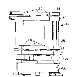
plurality of support structure 25 for joining together
spiders 13 and 14 at the top of the unit and spiders 15 and
16 at the bottom. Support structure 25 is shown in these
figures between adjacent arms 17A and 17B of the two
spiders 13 and 14. Figure 5a is a vertical sectional view
along line A-A of Figure sb, and illustrates an insulating
pad 30 between brackets 31 and 32 welded to the adjacent
edges of arms 17~ and 17B of respective spiders 14 and 13.
The brackets with the insulating pad therebetween are
bolted together by bolt and nut unit 33. As shown in
Figures 5b and 5c, the bolt used to mechanically connect
the two brackets together is elPctrically isolated
therafrom by a nylon or insulative sleeve 34 and a pair of
washers 35 and 3~ each made of an insulative material.
Figure 6 illustrates a simpler alternative
arrangement which may be used at one end only of the
reactor. Here a single spider 50 having a plurality of
arms 51 radiating from a central hub 52 is used in
-- 19 --
..,~
~3~23~
conjunction with a parallel stub arm 60 which is physically
alongside and supported by arm 51A o~ ~he spider, but
electrically isolated there~rom.
:
: - l9a -
Arm 51A has terminal B and stub arm 60 has terminal A.
One of the helices of each package 11 and 12 (as in Figure
2c) is terminated on the stub arm 60, while the other
is terminated on an arm of the spider 50, which is physically
180 away from the stub arm 60. This artifice insures
that adjacent points on conductors of the two helices
of each package differ by one half of a turn voltage,
as in the case where two full spiders are used, as previously
described. It should be noted that the arrangement of
Figure 6 may be used at only one end of the reactor.
In general, each package of the reactor must have a different
number of turns (not normally an integral number of turns)
in order to cause the required current division among
the packages. Thus, although the two helices of all packages
are connected to two common points at one end of the reactor,
as shown in Figure 6, the other ends of the helices must
terminate on various arms as shown in Figure 2c. As shown
in Figure 2c, the ends of the two helices in any package
terminate on dlfferent spiders at points 180 from each
other.
Figures 6A and 6B illustrate further physical
means of providing the equivalent of two spiders and comprise
essentially one structural member with two separate electrically
conductive spiders mounted thereon and carried thereby.
Figure 6A additionally illustrates in partial section
the physical structure of an air core reactor incorporating
the present invention.
Referring to Figure 6A, there is illustrated
a plurality of coil packages, -the two outermost of which
- 20 -
~3~23~
are designated llA and 12A, and are equlvalent t~ ~oil
packages 11 and 12 of Figure 2c or packages 1, ~, ~ of
Figure 4. Each coil package llA and 12A, however, differ
from coil packages 11 and 12 in that they have a number
of layers of windings radially one outside the other with
adjacent layers abutting but electrically insulated from
one another. Each layer has two or more helical windings
wound one on top of the other as shown in Figure 2c, and
designated therein Hl and H2. Each coil package llA and
12A is a rigid unit of glass reinforced plastics material
having the coil layers embedded therein. The coil packages
are radially spaced from one another by spacers ~, which
thus provides a plurality of vertical cooling ducts.
As in Figure 2c, there are two electrical spiders
at the top designated respectively 13A and 14A, and two
at the bottom designated respectively 15A and 16A. In
this embodiment, however, spiders 13A and 14A are supported
by one structural member designated 75. This structural
member can be an insulative material with spiders 13A
and 14A made of electrically conductive material mounted
directly thereon, or alternatively if member 75 is electrically
conductive then spiders 13A and 14A are moun-ted thereon
but separated therefrom by an insulative material. Spiders
15A and 16A at the bottom are similarly mounted on a rigid
structural member 75. The air core reactors of Figures
6A and 2a are the same differing only in construction
of the spiders and the mounting bases. The reactor of
Figure 6A is supported on insulator bushings 90 attached
directly to the arms of the bottom spider.
- 21 -
~3~23~a
In Figure 2a, in addition to this, there is
a glass fiber reinforced plastics material base 80.
Figure 6B is a cross-section through one spider
arm of the general type of spider shown in Figure 6A.
In Figure 6B the rigid member 75A of the spider is metal,
for example stainless steel, and the electrical conductive
portion of the spiders for connecting the coils in parallel
is a pair of channel pieces designated 76 and 77. These
channel pieces are electrically conductive and insulated
from member 75A by an insulator member 78. In this embodiment,
one of the bottom spiders, i.e. 15A in Figure 6A, is provided
by interconnecting at the hub all of channel pieces 76 carried
by the arms of rigid member 75A. Similarly, the spider 16A
associated with spider 15A is provided by interconnected
all of channel pieces 77 at the hub on the lower part of the
rigid member 75A.
Obviously the double spiders can take other
physical forms depending upon the structural requirements
of the unit in question.
The Use of a Double Spider at One End Only
A less sensitive system, but less expensive,
will result if a double spider is used at one end only
of the reactor. The sensitivity of this system may be
seen by considering again the results of Table 1. For
a fault near the mid-plane of the coil, the results of
cases 1 and 2 are valid if one uses the results for one
detec-tor only. For these faults, the simpler system is
half as sensitive as the system where double spiders are
used and the two detector signals added. For the case
~- 22 -
~3~23~
of a fault very close to the double spider, the results
in Table 1 for cases 3 and 4 apply lf one uses the currents
in the top detector only. For this case, the simpler
system has virtually the same sensitivity as the system
with double spiders at both ends. For the case of a fault
near the end of the reactor remote from the double spider,
the results in Table 1 Eor cases 3 and 4 apply if one
uses the currents in the bottom detector only. In this
case, the sensitivi-ty is severely reduced compared to
the full system. This is especially unfortunate since
the fault current is very much larger than the detector
current. The double spider used may be constructed as
described hereinbefore and illustrated in the drawings.
Protection of 3-Phase Reactor Bank
Where a 3-phase wye-connected bank of reactors
is to be protected, a modified scheme may be used as shown
schematically in Figure 7. In this figure, there are
three reactors designated A, B and C, and the two halves
of each reactor are shown for simplicity as a single inductance
rather than as "n" inductances in parallel, where "n"
is the number of packages in the reactor. In, for example,
reactor A the single inductance of one half is designated
LA1 and the other half as LA2. Each reactor is equipped
with double spiders at each end. The spiders at the line
end of each reactor are connected to a differential current
transformer discussed in the previous section and designated
in Figure 7 as CTA, CTB and CTC. The three sets of double
spiders at the other end are connected to form a double
wye, and a simple current transformer designated CTW is
- 23 -
~3~2~
connected between the two halves of the double wye. This
reduces the sensitlvity oE the wye-end detector slightly
but has the advantage that only four instead of six current
transformers and detectors are required. The foregoing
described current transformers as shown each have a detector
associated therewith.
Advantaqes_of the New Fault Detection System
The advantages of the new fault detection system
over those presently being used for air core reactors
are the following:
(1) Since the fault detection scheme detects faults
by comparing the currents into two halves of the reactor,
it is necessary that these two currents be virtually identical
under unfaulted conditions. Because the special construction
used in the protection system disclosed herein, namely
the use of two, identical, interwoven helices in each
package (or 2n, where n is an integer), ensures that the
two halves of the reactor are virtually identical, therefore
the residual difference in currents in the two reactor
halves under balanced conditions is very, very small.
This is necessary in order to detect very small faults
in the reactor.
(2) Because of the sensitivity, small faults may
be detectable long before any damage is done either to
the reactor or to connected equipment. Because the detector
signals are proportional to the fault, the faults are easily
detected and the coil can be disconnected very quickly.
(3) Because, in the preferred embodiment, double
- 24 -
~312~
spiders are used at both ends of the coil and each of
the interwoven helices in every package is connected to
a different set of spiders, it is very easy to check in
a foolproof manner for faults in the completed reactor
before it leaves the factory and at any time in the field
simply by disconnecting the double spiders at each end
and applying a high potential direct voltage between the
two halves of the coil. Because of the unique construction,
any fault will result in a connection between the two
halves which is easily detectable. Furthermore, the exact
location of the fault may be found by disconnecting the
two helices of each package in turn and performing a continuity
test to see if a connection exists between them, which
indicates a fault. Once the fault has been located in
a certain package, the exact position of the fault can
be detected by measuring the resistances between the top
ends and the bottom ends of the two helices comprising
the package.
(4) Because of the great sensitivity and reliability
of the fault detection system it is possible to protect
all types of reactors including those which were hitherto
very difficult to protect, for example smoothing reactors.
The main current in smoothing reactors is direct current
and it is very difficult to apply any protection system
to these coils. However, since DC smoothing reactors
always contain alternating ripple currents the present
system is directly applicable to protecting these reactors.
Furthermore, the reliability and sensitivity of the system
allows reactors to be employed in a more optimum manner
- 25 -
1 3 ~ ~ ~3;~
in some circumstances, for example in VAR protection systems.
It has been traditional in these sytems to build the reactor
in two completely separate pieces and to connect the sensitive
power semi-conductor circuits between the two halves of the
reactor in order to protect them. Using the present system, a
single reactor (which is considerably cheaper) may be used since
the sensitivity and reliability of the system can guarantee
that a reactor fault will be detected before damage can be done.
In the foregoing there is described, with reference
to the drawings, what in general may be described as an
air core reactox with two or more coaxial concentric coils
connected in parallel using a single structurally rigid
and electrically conductive spider at one end, and a structurally
rigid and two electrically conductive spiders at the other
end. The two electrically conductive spiders can be mounted
on one structurally rigid spider unit, or there can be
two separate structural units. In the preferred form,
there are two spiders at each end and all packages are
wound with at least two internested helices, and connections
of such helices to the spiders are offset circumferentially.
This provides an apparatus that can be readily checked
for minor faults, or alternatively the existence of a
~ fault can be used to initiate a shut down of a system
;~ or part of a system in which the reactor is used.
Physically rigid spiders have been described
which are electrically conductive and mounted on top of
one another or internested. As an alternative, the rigid
structural part may be one structural member and two electrical
spider parts mounted thereon.
:::
- 26 -