Note: Descriptions are shown in the official language in which they were submitted.
1312477
27395-8
The object of the invention is centred on prefabricated
construction, or partial prefabrication, of buildings, using basic
panels which are placed in pairs in a parallel manner at a certain
distance between the two, in order to form the external structure
of the building or construction. The panels can also be used
individually to form the internal walls.
The invention provides improvements in the construction
of buildings, comprising prefabricated panel s~ructures provided
with insulating material and having external walls, said panel
structures including panels arranged in pairs and the panels of
each pair being in parallel with each other and positioned at a
predetermined distance therebetween; means for maintaining
relative parallel position of said panels; means for supporting
and coupling said panels to a base of a building; a plurality of
means for coupling said panel structures with each other; means
for coupling said panelæ to a storey of a building immediately
above or below a storey formed of said panel structures, said
panels in each pair defining therebetween a hollow space filled
with concrete constituting a connecting element to couple the
20 panels of each pair to each other whereby sald panels in each
panel structure serve as a container for said concrete to provide
a stable assembly to simultaneously form an internal and an
external structure of the building, said means for coupling said
panel structures each including a profile element attached to an
external wall of a panel and a connecting member ~otally embedded
in a respective external wall made of concrete, said connecting
member having a base portion, a threaded cylindrical portion which
B
".
:`
.:
1 31 2477
27395-8
projects at right angles from said base portion towards an outer
face of said panel, said cylindrical portion beiny accessible from
an outside of the panel through a hole provided in each panel at
said element, and fastening means received in said cylindrical
portion.
Each of the panels preferably comprises by a framework
of rods to form a rectângular hollow body. The two larger
surfaces of the panel make up the basic framework thereof, and are
joined to each other by means of further rods, which afford
greater strength to the assembly. The hollow body is filled with
an insulating material, such as expanded polystyrene.
Obviously, the outer surfaces of the internal insulating
material lie within the framework, which latter is located
externally .
First of all, foundation footlngs or shoes are placed on
a concrete base or pad fixed on the bullding site, which footings
are provided with a transversal projection which extends upwards
at its upper end with two horizontal projectlons at either side
thereof, and two further horizontal projections.
Pairs of panels are placed on each of the upper
projections of the concrete footing whereas on the lower
projections, and on the inside thereof, are placed the beams which
form the base of the building and, on the outside thereof, the
outer concrete finishing of the building.
The panels are placed in a para]lel manner on the upper
projections, the non-facing surfaces of the panels having been
previously coated with a layer of concrete to provide two s~ooth
2a
B
1 31 2477
273~5-8
surfaces. During this operation, and prior to the laying of the
concrete, special elements for lateral coupling of the panels,
which
r~ `
'~
:; ~
2b
.,
~`
:`
,',
, ..
- 3 - 1 31 2477
shall be d~cl-ibt~d in detail further on, are likewise provided on
the said ou~er ~surfaces of the panels.
The pdlle]S, with coupling elemellts already lodged within the
concreLe-coated surfaced, are arranged to form a hori~ontal framework
over the shoe, each pair of panels being assembled with the aid of
rods which maintain the parallel position between the two panels.
The said rods are easily introduced through the insulating material
of the panels.
The central projection of the shoe in turn receives a Cil~uidl
shaft, corruga~ed, for example, which extends upwards ~hrough ~he
~llow ce~r~ ~r L~ ls.
The number an(l arrangemen~ of rods and the circu]ar shafts depend
on the general dimensions of the building.
Once the assembly has reached a suitable height, with an
appropriate number of panels, concrete is introduced into the hollow
cavity between èach pair of panels, and the mentioned elements for
lateral coupling of the panels are tightened. At the same time
concrete is introduced at the base of the shoe and at the coupling
areas of the beams.
Once a suitable height is reached, such as, for example, the
height of one storey or floor, the foregoing is repeatèd along the
external profi]e of the building to build a further storey. For this
purpose, the beam of this new storey leans on one of the panels of
the frame, specifically on the inner panels thereof, and further
panels are placed thereon.
The circular shafts located in the hollow cavity between the
panels end in h ndles for coupling to the handles of the circular
shafts locsted in ~he respectl~e hol~ow areas ot the upper storey.
,
_ 4 _ 1312477
The beams of said upper storey ~Ire likewise [illed wit:h concrete
aS7 S.llllt' iS introducl?(l be~ween the panels.
To form the corner closures )~ the buildin~, ~he inner l)ai)~'lS
are cut away in order that the concrete may occupy ~auch SpclCe~S.
The compartments or inner w~llc are formed hy ~in~l~ p?n~l~
filled with layers of concrete, this being done at the fac~Gry, which
are then coupled to the panels of the outer frame.
Furthermore, the inner walls are coupled to each other by means
ot single panels which are likewise previously filled with layers
of concrete.
In all connections ol the panel, a special epoxy adhe~sive for
concreLe is used.
To assist in assembly, improYe suitable contact be~wee,l th-
panels, and achieve the superficial alixnment of a certain builn'ing,
tile invention foresees the use of U-shaped angular profiles for inner
and outer corners, and straight pro~iles for smooth surfaces.
The said profiles are provided with holes at their base for
fastening to the panels, and, whenever necessary, are additionally
provided with lateral extensions, likewise provided with hole:., for
fastening of other auxiliary elements thereto.
As has already been mentioned hereinbefore, the panel surfaces
which were covered with concrete at the factory, are provided with
elements for regulating contact and separation between the panels
These regulating elements consist of bodies having a hollow,
cylindrical section with an inner thread, and on the end section
with six projections in the shape of a star, which element is embedded
in the concrete together with a bolt which is threaded thereto and
projects from the concrete layer.
1 31 2477
-- 5 --
The hole~ provi(le(l in the mclltiolle(l profiles in turn en~agl
cylindliccll elellll?~ having a peril)h~ral f]ange which couples to
the hase ot the sald llr~flies. The cyiindric~l ~ection of the sald
elements is iubstantially of the ~ame height as the widtll of the
IJ-shal>e(l profile.
~ ach of the said cylindrical elements i~s provide-i with two
openings which are displaced from the geon1etrical centre tllereof.
One o~ the openings is circular in shape and allows the passage there-
~hrough of the bolt from the panel, the other opening ~eing hexagonal
in ~section.
A workman may act with a spanner on t~ bushings through the
hex.lgonal apertures in order to fasten the pan~-ls together and, once
tllis has been done, the saicl apertures al]ow the washer and nuts
to be ad,usted in order to maintain a constant distance between the
two panels during hardening of the inner concrete.
racl~ of the pro~iles is provided with two holes. The angular
corner profiles are provided with extensions on which the said holes
are located in order to engage two panels at an angle.
The profiles may further serve as support for stays to maintain
the structure of the building during hardening of the concrete,
and may be of a grPater length.
In accordance with a varying embodiment of the invention, the
said paired panels comprising the outer wall may be substituted by
single panels, with a single framework of rods and two layers of
insulating material, leaving a hollow cavity therebetween, of variable
size, equivalent to that determined by the two paired panels of the
preceding embodiment. The rods used in the preceding embodiment are
unnecessary herein, and thus assembly is quicker and more accurate.
As regards all other features of the preceding embodiment, such
as seating on the shoe, filling with reinforced concrete, etc. these
are maintained.
A
.,
- 6 - 1312477
All the mentioned details may be observed in the attached sheets
of drawings, wherein the following are shown in an illustrative and
non-limitillg manner.
FiKure 1 shows an e1evation vlew of the tirst stage ot assembl,v
in accordance with the invention.
Figure 2 shows the second stage of the assembly.
Figures 3, 4 and 5 show different manners in which the panel~
are joined toKether, in accordance with the invention.
Figure 6 shows tlle arrangement for assembly of the externa1
profiles, in accordance with the invention.
Figure 7 shows a cross section along line I-I ot f1Kure 6~.
Figures 8 through 12 show detailed views of assembly of tne
external profiles.
Figures 13 and 14 show two views of the eccentric of separation
between the panels.
Figures 15 and 16 show an elevation and plan view, respectively,
of the element which is embedded in the panels for lateral coupling
thereof.
Figures 17 and 18 show, in similar views to those of figures
l and 2, the different embodiment of the invention based on a single
panel.
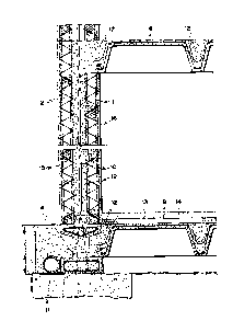
With reference to figure l, it can be observed that panels (l)
and ~2) are arranged parallel to each other on shoe (4). The external
surfaces (16) and (15) of the said panels are coated, in the factory,
with a layer of concrete with a thickness of, for example, 2.5 m/m,
and ti1e wires of each panel (not referenced) as well as the insulating
material contained therein, may be observed.
- 7 - 1312477
~ ach ~ ir of pane1~s is separate(l by rods (3) which maintain
the di~st,lnce tl-erel)etwee~ he number and position thereof d~l~ending
on the re~ irelrl(~llts and dimell.qiolls o~ ~h~ panels.
The shoe (4~ is placed on the lower cube (8) pr~vided on the
bui]ding site, and the base (7) of said shoe (4) in turn serves as
a support for the beams (9) which engage the lower surface of building
plates.
Further beams (6) may be observed on the upper part of the
drawings which beams correspond to a second storey of the building,
and on the inner panels of the framework.
. i
Given t~e above framework of the building, and with reference
to figure 2, the provision of a circular shaft (lo! on shoe (4~ can
be observed, the mass of concrete being introduced between the ~ane1s
to keep the circular shaft (10) in a central position. At the same
time, concrete (12) is likewise provided on the sides of the shoe (4)
and on beam (9). The perimetral drainage system (llj is likewise
shown in Figure 2.
The on-site concrete (12) fills the elevated perimetral hollow,
until it reaches the beam (6) of the first storey of the building,
which, as can be seen, rests on the inner panel. To aid this arrange-
ment, the panel of this storey is interrupted to house the end of
the beam (6).
The circular shaft (10) is interrupted by a handle to engage
the next circular shaft as the building progresses. A polystyrene
plate (13) and the lower floor (14) which completes the assembly
may likewise be observed in figure 2.
The various stages for coupling between panels are shown in
figures 3, 4 and 5. In figure 3, for example, an inner corner
corresponding to the coupling of two panels (1) is cut away to form
the corner, wherein the concrete (12) fills the space cut away and
the outer corner.
- 8 - t3~2477
Fi~ure 4 sllows ~he coupling be~ween a perimetral frame an-l an
internal panel. I30Lh side~ (15) and (16) of the inlern~l panel (17)
are likewi~e coated in the factory. Figure 5 shows the coupling
between internal l)anels, for example, between panels (17) and (17a).
A special epoxy adl-esive, which ai(ls coupling, is provided between
the side~s of ~anrl (17~ and between panels (17) and (17a).
With respect to figure 6, and with reference to the perimetral
frame which is partia11y shown, external corner profiles (20),
internal corner profile 22) and profile (21) should be noted, same
being arranged near each pair of panels in order to ensure coupling
therebetween.
J
The cross-~sections al`ong lines I-I of figure 6 are represented
in figure 7 and show element (27) which is embedded in the mass of
concrete (15) provided in the factory. Such element~s (26) are arranged
near the sides of panels (2), such that profiles (20), (21) and (22)
on being arranged on every ~wo panels, such as, for example, (36)
and (37) of figure 6, lies above elements ~27).
The said elements (27) and bolts (26) project from each panel,
and profiles (20), (21) and (22) are placed thereon, whilst bushings
(25~ are arranged in the apertures (33) thereof (figures 13 and 14).
Upon receiving bushings (25) in apertures (33), the profiles placed
over every two panels, and the bushings allow bolts (26) to cross
same through circular apertures (30) thereof.
In this respec~, figures 13 and 14 likewise show the two
apertures of bushing (25), which are displaced with respect to the
centre. Bushing (25~ fits tightly within the apertures (33) of the
profiles (20), (21) and (22) such that the blind hexagonal apertures
(29) may be acted upon in order to brin8 closer panels (36) and (37)
of figure 6, before d~finitive tithtening of threaded bolt (~6).
:
- 9 ~ 1 31 2477
Profile~s (2()~, ~21) and (25) may be provided with exten.sions
or plates, such a~s (35) an(l (23) with openings for receiYing auxiliary
elements connected t(! stays which are fixed to the base, in order
to hold the complete assemb1y.
Finally, ~igures 15 and l6 show element (27) embedded in the panels,
and wherein the cylindrical portion (31, and rear projections (32
thereof, may be observed.
In the varying embodiment of figures 17 and 18, it has been
foreseen that each wall or modular wall, of the external structure
is comprised by a single pane~ 1', arranged on the same shoe ~4~,
and compri~ed l)y the same two~ thermal1y insu1ating layers l and 2,
provided on their external su~rfaces with coatings 15 and 16 of
concrete reinforced with respective trusses, but with the particular-
ity that same are joined to each other by means of single rod
structure 5, which ohviously crosses the inner hollow of the ~anel,
thereby coupling and stiffening the two halves thereof, wherefore
in this case rods 3 of the front embodiment are not required.
Apart from this single panel structure of the wall modulus,
the remaining structural features are the same as those of the
preceding embodiment.
The essential advantages afforded by the invention over
traditional techniques are obvious; for the cost thereof is consider-
ably lower than that of conventional constructions, both as a result
of the materials used and of the quickness in assembly. In turn,
insulation is total from both the outside and the inside of the
building, for both surfaces have insulating properties. A greater
soundproofing is likewise obtained, this being important for good
habitability.