Language selection

Search

Patent 1312509 Summary

Third-party information liability

Some of the information on this Web page has been provided by external sources. The Government of Canada is not responsible for the accuracy, reliability or currency of the information supplied by external sources. Users wishing to rely upon this information should consult directly with the source of the information. Content provided by external sources is not subject to official languages, privacy and accessibility requirements.

Claims and Abstract availability

Any discrepancies in the text and image of the Claims and Abstract are due to differing posting times. Text of the Claims and Abstract are posted:

  • At the time the application is open to public inspection;
  • At the time of issue of the patent (grant).
(12) Patent: (11) CA 1312509
(21) Application Number: 1312509
(54) English Title: CUBICLE SEPARATION
(54) French Title: CLOISON
Status: Expired and beyond the Period of Reversal
Bibliographic Data
(51) International Patent Classification (IPC):
  • A01K 1/00 (2006.01)
(72) Inventors :
  • SPINDER, PIETER
(73) Owners :
  • REDNIPS HOLDING B.V.
(71) Applicants :
  • REDNIPS HOLDING B.V.
(74) Agent: KIRBY EADES GALE BAKER
(74) Associate agent:
(45) Issued: 1993-01-12
(22) Filed Date: 1988-12-21
Availability of licence: N/A
Dedicated to the Public: N/A
(25) Language of filing: English

Patent Cooperation Treaty (PCT): No

(30) Application Priority Data:
Application No. Country/Territory Date
87 03133 (Netherlands (Kingdom of the)) 1987-12-24

Abstracts

English Abstract


- 1 -
A B S T R A C T
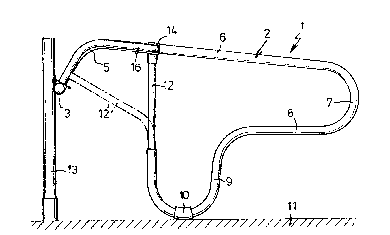
By laterally connecting the shoulder beam of a cubicle separation
to the separation that is bent in mushroom-shape and by bending it
towards the head beam that serves as the fulcrum for the complete
structure of separation and shoulder beam, and extremely simply
constructed tiltable cubicle separation is obtained.


Claims

Note: Claims are shown in the official language in which they were submitted.


Claims:
1. A cubicle separation including a head beam, a
separation pivotally attached to the head beam, and a
shoulder beam having one end connected to the separation and
an opposite end pivotally connected to the head beam such
that an animal can raise the separation by lifting the
shoulder beam.
2. The cubicle separation of claim 1, wherein the
shoulder beam includes two portions extending substantially
at right angles to one another.
3. The cubicle separation of claim 2, wherein the two
portions are integrally formed.
4. The cubicle separation of claim 1, 2, or 3,
wherein the shoulder beam extends rearwardly and upwardly
from the head beam.
5. The cubicle separation of claim 1, 2 or 3, wherein
the shoulder beam comprises a substantially horizontal
portion with opposite first and second ends, and a bent
portion with opposite first and second ends, the horizontal
and bent portions being substantially perpendicular to one
another; the first end of the horizontal portion being
connected to the first end of the bent portion; the second
end of the horizontal portion being fixed to the separation
such that the horizontal portion extends substantially
perpendicular thereto; and the second end of the bent
portion being pivotally attached to the head beam.
6. The cubicle separation of claim 1, wherein the
separation includes a leg portion for supporting the
separation on a support surface.
7. The cubicle separation of claim 6, wherein the leg
portion is formed integrally on the separation.

Description

Note: Descriptions are shown in the official language in which they were submitted.


131250q
Cubicle separation
The invention relates to a cubicle separation for use with
animals, such as cattle.
Such a cubicle separation is known from ~uropean patent
application of Donkers published under No. 090470 October 5,
1983. The measures to make the shoulder beam upwardly
movable consist in this known cubicle separation in slidable
connections between the shoulder beam and the separations
disposed on either end thereof. These connections have to
compensate the extension of the shoulder beam if this would
not remain parallel to it~elf when moving it upwardly. This
arrangement entails extra costs, both with respect to
manufacture and with respect to maintenance.
The invention aims to improve the above-describsd situation
and consists of a cubicle separation including a head beam,
a separation pivotally attached to the head beam, and a
shoulder beam having one end connected to the separation and
an opposite end pivotally connected to the head beam such
that an animal can raise the separation by lifting the
shoulder beam.
In a preferred embodiment the connection comprises a
three-dimensional clamp to which also a tube portion,
extending substantially vertical in its rest position, of
the separation is connected.
:
The invention will be further elucidat~d hereafter on the
basis of the drawing, showing as an example an embodiment of
a cubicle separation according to the invention. In the
drawing:
J :;~

1312509
figure 1 shows a side view of ~he invented device and
figure 2 shows a top view of figure 1.
The cubicle separation shown in the drawing comprises a separation
1 of tube material that is bent in mushroom-shape, constructed of
a long tube 2 that at its one outer end is connected to a sleeve 4
that is rotatable about a head beam 3. The long tube 2 in its po-
sition shown in the drawing extends upwardly with an arcuate tube
portion 5 and from khere rectilinearly downwards in a top portion
6, sloping towards a semi-circularly and downwardly bent end por-
tion 7 that merges into a horizontal bottom portion 8. However, it
is a].so possible that the top poxtion 6 sloping downwardly in the
(drawn) rest position extends substantially horizontally. About
halfway its length the long tube 2 of the separation 1 has a por-
tion 9 bent in reversed U-shape. At the lowest point oE the por-
tion 9 bent in U-shape a rubber or plastic sleeve 10 is disposed,
with which the separation 1 rests on the floor 11. This sleeve
; serves in the first place as a buffer stop, but it may also serve
to protect the tube from corrosion due to the animals' excrements.
'
In the free end of the portion 9 bent in U-shape a short tube 12
of smaller diameter is welded tightly, which tube connects the end
of the long tube 2 to its arcuate tube portion 5.
At the usual distance from the head beam 3, which is supported on
the floor 11 by means of poles 13, clamps 14 have been mounted on
the top portions 6 of the separations, to which clamps a shoulder
beam 16 is connected by means of a bolt 15.
In the preferred embodiment the short tube 12 extends substan-
tially vertical in the rest position of the separation and the
clamp 14 is a three-dimensional clamp. However, the short tube may
also be deflected, as drawn by the dotted line, to a portion of
the tubular tube section 5 that is closer to the head beam 3, and
welded thereto. The shoulder beam 16 may then be connected by

1312509
3 --
means of a T-clamp 1~ to the top portion 6/ but this embodiment
appears to be less stable.
The shoulder beam 16 comprises a piece of tube material that is
bent in such a manner that a horizontal portion 17 is created that
merges into a rearwardly and downwardly bent portion 18 that at
its end is connected to a sleeve 19 that is pivotable about the
head beam and that is in the vicinity of the sleeve ~ of a next
separation. The shoulder beam is at such a distanc~ from the floor
11 that the cattle cannot crawl through under it; for cows this is
+ 80 cm. The shoulder beam 16 is then + 110 cm above the floor. If
a cow should walk against it with its neck, it would lie down. If
the animal wants to get up, it can move one of the separa-tions 1
of its cubicle 1 upwards by means of the shoulder beam 16.
Other embodiments than the one shown in the drawing are also with-
in the scope of the claims.

Representative Drawing
A single figure which represents the drawing illustrating the invention.
Administrative Status

2024-08-01:As part of the Next Generation Patents (NGP) transition, the Canadian Patents Database (CPD) now contains a more detailed Event History, which replicates the Event Log of our new back-office solution.

Please note that "Inactive:" events refers to events no longer in use in our new back-office solution.

For a clearer understanding of the status of the application/patent presented on this page, the site Disclaimer , as well as the definitions for Patent , Event History , Maintenance Fee  and Payment History  should be consulted.

Event History

Description Date
Time Limit for Reversal Expired 2003-01-13
Letter Sent 2002-01-14
Grant by Issuance 1993-01-12

Abandonment History

There is no abandonment history.

Fee History

Fee Type Anniversary Year Due Date Paid Date
MF (category 1, 5th anniv.) - small 1998-01-20 1997-12-17
Registration of a document 1998-09-17
MF (category 1, 6th anniv.) - small 1999-01-12 1999-01-07
MF (category 1, 7th anniv.) - small 2000-01-12 2000-01-10
MF (category 1, 8th anniv.) - small 2001-01-12 2001-01-02
Owners on Record

Note: Records showing the ownership history in alphabetical order.

Current Owners on Record
REDNIPS HOLDING B.V.
Past Owners on Record
PIETER SPINDER
Past Owners that do not appear in the "Owners on Record" listing will appear in other documentation within the application.
Documents

To view selected files, please enter reCAPTCHA code :


To view images, click a link in the Document Description column. To download the documents, select one or more checkboxes in the first column and then click the "Download Selected in PDF format (Zip Archive)" or the "Download Selected as Single PDF" button.

List of published and non-published patent-specific documents on the CPD .

If you have any difficulty accessing content, you can call the Client Service Centre at 1-866-997-1936 or send them an e-mail at CIPO Client Service Centre.


Document
Description 
Date
(yyyy-mm-dd) 
Number of pages   Size of Image (KB) 
Cover Page 1993-11-09 1 14
Claims 1993-11-09 1 39
Abstract 1993-11-09 1 10
Drawings 1993-11-09 1 22
Descriptions 1993-11-09 3 94
Representative drawing 2000-08-11 1 11
Maintenance Fee Notice 2002-02-11 1 179
Examiner Requisition 1992-01-28 1 66
PCT Correspondence 1992-11-02 1 39
Prosecution correspondence 1992-05-28 2 93
Fees 1997-01-06 1 63
Fees 1996-01-02 1 56
Fees 1994-12-14 1 54