Language selection

Search

Patent 1313060 Summary

Third-party information liability

Some of the information on this Web page has been provided by external sources. The Government of Canada is not responsible for the accuracy, reliability or currency of the information supplied by external sources. Users wishing to rely upon this information should consult directly with the source of the information. Content provided by external sources is not subject to official languages, privacy and accessibility requirements.

Claims and Abstract availability

Any discrepancies in the text and image of the Claims and Abstract are due to differing posting times. Text of the Claims and Abstract are posted:

  • At the time the application is open to public inspection;
  • At the time of issue of the patent (grant).
(12) Patent: (11) CA 1313060
(21) Application Number: 1313060
(54) English Title: PRESSURE TRANSDUCER WITH CONDUCTIVE POLYMER BRIDGE
(54) French Title: TRANSDUCTEUR DE PRESSION AVEC PONT POLYMERIQUE CONDUCTEUR
Status: Expired and beyond the Period of Reversal
Bibliographic Data
(51) International Patent Classification (IPC):
  • G01L 9/04 (2006.01)
  • G01L 1/22 (2006.01)
  • G01L 9/00 (2006.01)
(72) Inventors :
  • FRANK, THOMAS P. (United States of America)
(73) Owners :
  • MEDEX, INC.
(71) Applicants :
  • MEDEX, INC. (United States of America)
(74) Agent: MACRAE & CO.
(74) Associate agent:
(45) Issued: 1993-01-26
(22) Filed Date: 1988-11-25
Availability of licence: N/A
Dedicated to the Public: N/A
(25) Language of filing: English

Patent Cooperation Treaty (PCT): No

(30) Application Priority Data:
Application No. Country/Territory Date
132,014 (United States of America) 1987-12-14

Abstracts

English Abstract


Abstract of the Disclosure
A pressure transducer is produced by molding a
diaphragm from a high temperature thermoplastic. The diaphragm
is molded in a cup shape having thick edges and a thin,
flexible central portion onto which the strain gauge is to be
formed. A Wheatstone bridge of conductive polymers is screen
printed onto the surface of the thin central diaphragm of the
molded element. The conductive polymers can be trimmed to a
desired resistance value using a Nd-YAG laser or abrasive-type
trimmers. The conductive polymers are baked onto the substrate
and metal conductors are printed on the surface of the
substrate at the ends of the resistor elements. These metal
conductors are connected by a conductive epoxy to lead wires by
which the sensor is connected into its monitoring circuit.


Claims

Note: Claims are shown in the official language in which they were submitted.

THE EMBODIMENTS OF THE INVENTION IN WHICH AN EXCLUSIVE
PROPERTY OR PRIVILEGE IS CLAIMED ARE DEFINED AS
FOLLOWS:
1. A pressure transducer comprising:
a molded high temperature, thermoplastic
substrate having a thin flexible section,
at least one conductive polymer resistor
printed on said flexible section,
said resistor changing its resistance when
said substrate is flexed.
2. A pressure transducer comprising:
a molded substrate formed from a high
temperature thermoplastic material having a thick
border and a thin central section,
a resistance bridge formed of conductive
polymer resistors printed and baked on said thin
central section, said resistors having ends,
and conductors connected to the ends of said
resistors.

-7-
3. A transducer as in claim 2 in which said
conductors are printed on said substrate and leads are
connected to said conductors with a conductive epoxy.
4. A transducer as in claim 2 in which said
thick border is circular.
5. A transducer as in claim 2 in which said
thick border is circular and the center of said
central section has a thick integrally-molded boss
forming a rigid center.
6. A transducer as in claim 2 in which said
thin central section has a thickness in the range of
about 5 to 15 mils.
-7-

Description

Note: Descriptions are shown in the official language in which they were submitted.


13~306~
This invention relates to a pressure sensor
of the type that is used in a blood pressure
transducer.
Blood pressure transducers are known which
employ a silicon sensor. The silicon sensor is very
small, being a fraction of a square inch in area. It
is circular in cross section and has a Wheatstone
bridge strain gauge formed of piezo-resistive elements
diffused into the silicon substrate. The silicon
substrate is chemically etched away on the surface
opposite the Wheatstone bridge so as to form a thin
silicon diaphragm that flexes when subjected to
pressure causing the resistors in the Wheatstone bridge
strain gauge to be stressed to produce an indication of
the applled pressure. The manufacturing process for
the silicon sensor is necessarily expensive.. Further,
the sensor is temperature-sensitive and therefore
requires a temperature compensation circuit.
sd/~

`` 1313~6~
Strain gauges have been formed in other
ways. It is known to form a strain gauge by deposit-
ing a thick film resistor on alumina. The resistor
must be baked at a high temperature of the order of
800F. Hence, a ceramic such as alumina is required
as the substrate.
It is also known to form strain gauges from
conductive polymers, again using alumina as a sub-
strate. These thick film resistor and conductive
polvmer strain gauges have all been massive compared
to the tiny silicon sensor.
An objective of the present invention has
been to provide a less expensive sensor to replace the
silicon sensor.
This objective of the invention is attained
by molding a diaphragm from a high temperature thermo-
plastic. The diaphragm is molded in a cup shape
having thick edges and a thin, flexible central
portion onto which the strain gauge is to be formed.
With the molding of the plastic, the expensive
diffusion process and etching steps required with a
silicon sensor are eliminated.
A Wheatstone bridge of conductive polymers
is screen printed onto the surface of the thin central
diaphragm of the molded element. The conductive
polymers can be trimmed to a desired resistance value
using a Nd-YAG laser or abrasive-type trimmers. The
conductive polymers are baked onto the substrate at

` _3_ ~31306~
over 400F. Metal conductors are printed on the
surface of the suhstrate at the ends of the resistor
elements. These metal conductors are connected by a
conducti~e epoxy to lead wires by which the sensor is
connected into its monitoring circuit.
Among the advantages of the invention are
that it is much less expensive than the silicon
sensor, being a small fraction of the cost of the
silicon sensor. The sensor of the present invention
is substantially temperature-insensitive and hence
requires no temperature compensation network as is
required with the silicon sensor.
The several features and advantages of the
present invention will become more readily apparent
from the following detailed description taken in
conjunction with the accompanying drawings in which:
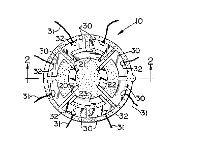
Fig. 1 is a plan view of a sensor of the
present invention;
Fig. 2 is a cross-sectional view taken along
lines 2-2 of Fig. l; and
Fig. 3 is a cross-sectional view similar to
that of Fig. 2~of an alternative embodiment.
Referring to the drawings, the sensor is
indicated at 10 and has a substrate 11 formed of a
thermoplastic resin. The preferred material for the
substrate is Ryton R4 (40% glass, polyphenylene
sulfide) manufactured by Phillips Chemical Co. Divi-
sion of Phillips Petroleum. Other materials are
*trade-mark
-3-
.. . .. .
- .
. :
,

_4_ 1 313060
polyethersulfone (VITREX PES by Imperial Chemical
Industries), polyetheretherketone (VITREX PEEK ) by
Imperial Chemical Industries, polyetherimide (ULTEM
1000 by General Electric) and liquid crystal polymer
(Vectra A150 by Celanese Advanced Technology Company).
The substrate has a thick perimeter 12 having a series
of stress-relieving cavities 13 spaced around its
circumference. The perimeter is preferably about
0.150" thick.
The central portion consists of a thin
diaphragm 15 that has a thickness in the range of 5 to
15 mils. The thickness of the diaphragm is governed
by two major conslderations. The thicker the dia-
phragm, the greater is the linearity of the output.
The thinner the diaphragm, the greater is its sensi-
tivity. Therefore, a thickness of about 10 mils
producing a sensitivity of 15 ~v/v/mmHg is preferred.
J
The diaphragm is preferably about 0.500" in diameter.
The diameter of the entire substrate is about .800".
Referring particularly to Fig. 1, conductive
polymer resistors 20, 21, 22 and 23 are screen-printed
on the diaphragm.
Printed conductor material such as paladium
silver is applied as at 30 to the ends of each of the
resistive elements 21-23. Leads 31 are connected to
the printed conductor material by a conductive epoxy
32.
*trade-mark

` - ~313060
In the alternative embodiment of Fig. 3, the
element differs only from the element of the previous
embodiment in the thick center portion 40. The center
portion is preferably a thickness in the range of
0.080" to 0.090" and is l/4" in diameter. Sensors
having rigid centers are known. The rigid centers are
used for increasing the effective area and for gen-
erating high stresses in the diaphragm at lower
deflection levels, thus improving the overall per-
formance of the diaphragm.
From the above disclosure of the general
principles of the present invention and the preceding
detailed description of a preferred embodiment, those
skilled in the art will readily comprehend the various
modifications to which the present invention is
susceptible. Therefore, I desire to be limited only
by the scope of the following claims and equivalents
thereof:
,

Representative Drawing
A single figure which represents the drawing illustrating the invention.
Administrative Status

2024-08-01:As part of the Next Generation Patents (NGP) transition, the Canadian Patents Database (CPD) now contains a more detailed Event History, which replicates the Event Log of our new back-office solution.

Please note that "Inactive:" events refers to events no longer in use in our new back-office solution.

For a clearer understanding of the status of the application/patent presented on this page, the site Disclaimer , as well as the definitions for Patent , Event History , Maintenance Fee  and Payment History  should be consulted.

Event History

Description Date
Inactive: IPC from MCD 2006-03-11
Time Limit for Reversal Expired 1998-01-26
Letter Sent 1997-01-27
Grant by Issuance 1993-01-26

Abandonment History

There is no abandonment history.

Owners on Record

Note: Records showing the ownership history in alphabetical order.

Current Owners on Record
MEDEX, INC.
Past Owners on Record
THOMAS P. FRANK
Past Owners that do not appear in the "Owners on Record" listing will appear in other documentation within the application.
Documents

To view selected files, please enter reCAPTCHA code :


To view images, click a link in the Document Description column. To download the documents, select one or more checkboxes in the first column and then click the "Download Selected in PDF format (Zip Archive)" or the "Download Selected as Single PDF" button.

List of published and non-published patent-specific documents on the CPD .

If you have any difficulty accessing content, you can call the Client Service Centre at 1-866-997-1936 or send them an e-mail at CIPO Client Service Centre.


Document
Description 
Date
(yyyy-mm-dd) 
Number of pages   Size of Image (KB) 
Cover Page 1993-11-09 1 17
Abstract 1993-11-09 1 22
Drawings 1993-11-09 1 26
Claims 1993-11-09 2 33
Descriptions 1993-11-09 5 140
Representative drawing 2002-03-19 1 16
PCT Correspondence 1992-10-27 1 21
Prosecution correspondence 1992-07-02 3 96
Examiner Requisition 1992-03-31 1 61
Prosecution correspondence 1991-05-03 4 92
Examiner Requisition 1991-03-20 1 59
Fees 1996-01-08 1 39
Fees 1994-12-28 1 59