Note: Descriptions are shown in the official language in which they were submitted.
1313~7g
Film Cassette
The invention relates generally to the
field of photography, and particularly to a film
cassette containing roll film.
In convsntional 35mm film manufacturers'
cRssettes, such as manu~actured by Eastman Kodak Co.
and Fu~i Photo Film Co. Ltd., the filmstrip ls wound
on a flanged spool which is rotatably supported
within a cylindrical shell. A leading end section
of the filmstrip approximately 2 1/3 inches long,
commonly referred to as a "~ilm leader", protrudes
from a light-trapped slit or mouth of the cassette
shell. One end of the spool has a short axi~l
extension wh~ch pro~ects from the shell, enabling
the spool to be turned by hand. If the spool ls
initially rotated l-n an unwinding direction, the
film roll inside the shell will tend to expand
radlally since the inner end of the ~ilmstrip is
attached to the spool, and ths fogged leader section
protruding from the slit will remain st~tionary.
The film roll can expand radially until a
~; non-slipping relatlon is establishe~ between its
outermost convo~ution and the inner curved wall of
the shell. Once this non-slipping relation exists,
2~ there is ~ binding ef~ect between the film roll and
the shell which prevents further rotatlon of the
spool in the unwinding directiDn. Thus, rotation of
the spool in the unwinding direction cannot serve to
advance the filmstrip out of the shell, and it is
necessary ln the typical 35mm still camera to engage
the protruding leader section to draw the filmstrip
out of the shell.
A 35mm film cassette has been proposed
which, unlike conventlonal ~ilm cassettes, can be
operated to Automatically advance the filmstrip out
-
' . ..
,
~L3~3~79
of the cassette shell by rotating the film spool in
the unwinding direction. The film leader normally
does not protrude from the cassette shell.
Spec~lcally, in prlor art U.S. Pat. No. 4,423,943,
S granted January 3, l9B4, there is disclosed a ~ilm
cassette wherein the outermost convolutlon of the
~ilm roll wound on the film spool is radially
constrained by respective circumferentlal llps of
two axially spaced flanges of the spool to prevent
the outermost convolution from contacting an inner
curved wall of the cassette shell. The traillng end
o~ the filmstrip is secured to the ~llm spool, and
the leading end of the filmstrip is slightly tapered
along one longitudinal edge purporkedly to allow it
to extend from between the circumferential lips and
rest against the shell wall. Durin~ initial
unwinding rotati~n ~f the film spool, the leading
;~ end ~f the filmstrip is advanced along the shell
wall until it reaches an entry to a film pAssageway
in the cassette shell. Then, it is advanced into
and through the film passageway to the outside of
the cassette shell. The passageway ha~ a width
which iR slightly less than the width of the
~ilmstrip, thus resulting in the ~ilmstrip being
transversely bowed as it is uncoiled ~rom the film
spool, and thereby facilitating movement of the
~ longitudinal ~llm edges under the circumferenti~l
; lips o~ the respective flanges. However, transverse
bowing of the filmstrip to move its longitudinal
edges under ~he circumferential lips results in
increased friction between the filmstrip and the
~ilm spool which will impede advance of the
f~lmstrip from the cassette shell and may damage the
filmstrip.
~ 35 The invention relates to a film cassette
: '
~3~L3~79
wherein ~ ~ilm spool when rotated in the unwinding
direction ~utomatically advances a ~ilm leader out
o~ the c~ssette shell. However, in contra-
distinction to prior art U.S. Pat. No. 4,423,943,
this is done without po sibly damaging the filmstrip.
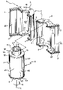
FIG. 1 ls ~n exploded perspect~ve vlew o~
an i~proved film cassette ~ccording to a preferred
embodiment of the invention;
FIG. 2 is an elevation view in cross-
sect~on o the improved film c3ssette; and
~ IG. 3 is an end view in cross-section of
the improved ~ilm c~ssette.
According to a preferred embodiment of the
invention, there is provided a film cassette (1)
wherein a film spool (S) ls rotatable lndependently
of a pair of coaxiaily spaoed disks (51, 53). The
two disks (51, 53) have respective annula~
circumferential l~ps (59, 61) which prevent the
outermost leader convolution (47) of a f~lm roll
~ (37) wound on the spool core (23~ from
clock-sprlnging into con~act wi~h the cassette shell
~: (3). When the spool core (23) is initially rotated,
the disks ~51, 53) c~n remain substantially
~ stationary and the fllm roll (37), since its inner
;~ 25 end (39) is secured to the spool core, tends to
expand radially to ensure a non-slipping relation
between the outermost le~der convolution (47) and
the circumferenti~l lips (59, 61). Then, rotation
o~ the spool core (23) must rotate the disks (51,
53) and st3tionary internal spreaders (S5, 67) will
deflect successive portions (59', 61') o~ lips (59,
61) to an ~xi31 dimension excseding the film width,
thereby allowing corresponding portions of the
;: outermost leader convolution ~47) to exit from the
r~dial conf1nement of the lips. Stationary intern~l
guides (73, 75) direct the ~reed ~orward end (45) of
~ ., ~ . . .
,: :
13~307~
the outermost leader convolution (47) to the
c*ssette opening (25). Su~icient film thrust ls
provlded by the spool core (23) as lt is rotated, to
thread the Film leader (43) along the cassette
opening ~2S) to the outside o~ the cassette shell
(3).
The invention is disclosed as being
~mbodied pre~erably in a 35mm film cassette.
Because the features of this type of f~lm cassette
~re generally well ~nown, the description which
follow~ is directed in particular to elements
forming part o~ or cooperating directly with the
disclosed embodiment. It ls to be understood,
however, that other elements not speci~ically shown
or described may take various forms known to persons
of ordinary skill in the art.
Re~erring now to the drawings, FIGS. 1-3
depict an improved 35mm fil~ cassette 1 comprising a
light-tight c~ssette shell 3 and a ~ilm spool 5
rotatable about an axis X within the c~ssette
shell. The cassette shell 3 consists of two shell
halves 7 ~nd 9 which are mated along respective
grooved and stepped ~dge portions ll and 13. The
; 25 mated halves 7 ~nd 9 de~ine upper and lower ali~ned
openings 15 and 17 ~or relatively longer and shorter
opposite end extensions 19 and 21 of a spoo~ core or
hub 23. Also, they de~ine a light-trapped film
passage slit or mouth 25. The light-trapping means
for preventing amblent light ~rom enter~ng ~he film
passage slit Z5, although not shown, may be a known
black velvet or plush ma~erial which lines the
interior of the sllt.
The spool core 23 as shown in FIGS. 1-3
includes rel2tively longer and shor~er coaxial holes
j
,
~3~
27 ~nd 29 opening at the respective longer ~nd
shorter opposite end extensions 19 ~nd 21 o~ the
spool core. A pair of spaced keying ribs 31 and 33
integrally Formed with the spool core 23 are located
within the longer coaxial hole 27, and a single
keying rib 35 similarly formed wtth the spool core
is located within the shorter coaxial hole 29. The
several keying ribs 31, 33, and 35 according to
custom may be engaged to rotate the film spool ~n an
unwinding dlrection indicated by the arrow U in FIG.
: 1, or to rotate the spool in winding direction
opposite to the unwinding direction.
A roll 37 o~ convoluted 35mm film having ~
substantially uniform width is wound about the spool
core 23~ ~s indic~ed in F~G. 3, the film roll 37
h~s an inner or trailing end 39 attached to the
spool core 23 by a suitable piece of adhesive t~p8
41 and a leader sectlon 43. The leader section 43
has a leading or orward end 45 and comprises 2-3
convolutions of the film roll 37. One of these
convolutions is the outermost convolution 47 and
:: ~no~her o~ them is the next inward succeed~ng
convolution 49.
A pair o~ ~lexible identical flanges or
disks 51 and 53 ~re coaxially spaced alon~ the spool
core 23 to lightly rest against the opposite flat
ends of the film roll 37. The two disks 51 and 53
cover the opposite ends of the ~llm roll 37 and they
have respective central holes 55 and 57 through
whlch the spool core 23 lon8itud1nally extends in
loose rela~ion to permi~ rot~tion of the spool core
relative to the disks. Although not shown, it ls
possible for ~he spool core 23 to include integral
radially extending ~langes disposed between the
opposite ends o~ the film roll 37 and the respective
~3~ 9
disks 51 and 53. The two disks 51 and 53 have
respect1ve continuous circumferential annular lips
59 and 61 which extend at right angles to the
peripheries of the disks to radially confine the
outermost convolution 47 of the film roll 37,
thereby to prevent the fllm roll from radially
expanding or clock-springing into contact with an
inner curved wall 63 of the cassette shell 3. As
shown in FIG. 1, the leading end 45 of the film roll
37 is similarly confined by the circumEerential lips
59 snd 61. However, the leadin~ end 45 may be
tapered to allow it to slightly protrude from
between the two lips 59 and 61.
A pair o~ rigid identical spreader surfaces
65 and 67 are Eixed to the cassette halF 9 at
separate locations inwardly of the film passa~e slit
25 as shown in FIGS. 2 and 3. The two spreader
sur~aces 65 and 67 de~lect opposite llmited portions
; 59' and 61' of the respective lips 59 and 61
ttogether with the disks 51 and 53~ axially away
~rom each other to ~n axial dimension slightly
exceedlng the f~lm width. See FIG. 2. In essence,
the deflected portions 59' and 61' of th~ two lips
59 and 61 are axially spaced suf f iciently to pre~ent
25 thos~ portions o~ the l~ps from radia~ly con~inin~
corresponding portions of the outermost convolut~on
47 of the ~ilm roll 37. As indicated in FIGS. 1 and
- 2, the remaining portions of the two lips 59 and 61
~re maintained in place via inner semi-circular flat
support sur~aces 69 and 71 o~ the cassette shell 3,
which abut the respective disks 51 and 53 except in
the general viclnity of the ~wo spreader surfaces S5
and 67. Thus, the remaining portions o~ the two
llps 59 ~nd 61 must con~inue to radially conflne the
outermost convolution 47.
13~L3~79
When the spool core 23 is initially rotated
ln the unwinding direction ~, the two disks Sl and
53 c~n remain substantially stationary snd the film
roll 37, since its inner end 39 ls attached to the
spool core, tends to expand radially to ensur~ a
fi~m non-slipping relat~on between the outermost
convolution 47 of the film roll ~nd the circum-
ferential lips 59 and 61 of the disks. Then,
rotation ~f the spool core 23 in the same direction
will similarly rotate the two disks 51 and 53. ~s
result, the two spreader surfaces 65 and 67 will
d~flect successive portions of the circumferential
lips 59 and 61 axially away from each other as the
respective portions are rotated past the spre~der
surfaces. The deflected portions ~9' and 61' of the
two lips 59 and 61 are returned to their original
non-de~lected cond1tion by means of the semi-
circular ~lat support surEaces 69 and 71 bearing
agains~ the respective disks 51 ~nd 53 at locations
: 20 remote ~rom the spreader surfaces 65 and 67. As can
be apprecl~ted from FI~. 3, the leading end 4~ of
the film roll 37 will be ~reed from the radial
conflnement o~ the two lips 59 and 61 in the general
: ~iclnity Qf the spreader sur~aces 65 and 67 and it
will be advanced against a pair of r~gid identical
stripper-guide surfaces 73 and 75 integrally ~ormed
wl$h the respective spreader surfaces. The two
~ stripper-guide surfaces 73 and 75 operate to direct
.~ the leading end 45 1nto the film passage slit 25,
thereby allowing succeeding portions o~ the
outermost convolution 47 to be freed from
corresponding portions o~ the two lips 59 and 61 as
those portions o~ the lips are deflected by the two
spreader sur~aces 65 and 67. Consequently,
contlnued rot~tion of the spool core 23 will thrust
'~
-` ~3~L3~'79
the leader section 43 of the film roll 37 ~rom the
cassette shell 3.
The invention has been described with
reference to a preferred em~odiment. However, it
will be appreciated that variations snd
modifications can be effected within the ordinary
skill in the art without departing from the scope of
the invention. ~or example, the leading end 45 of
the film roll 37 could ini~ially be located within
the film passage slit 25 rather than be radially
confined by the circum~erential lips 59 and 61 o~
the two disks 51 and 53.
~5
" 30
'''
~ 35