Note: Descriptions are shown in the official language in which they were submitted.
1 31 ~259
-- 1 --
CASS~TT~ TYP~ R~CO~DIN~ AND/OR R~PRODUCING APPr~AT~S
BAC~G~O~D QF ~H~ T~V~ION
The present invention relates generally to a
cassette type recording and/or reproducing apparatus
and, more particularly, to a cassette type recording
and/or reproducing apparatus having a chassis capable of
mounting a casse-tte on an upper part thereof. More
particularly, this invention relates to a thin cassette
recording apparatus having a chassis with a recess
wherein the tape reels and the mode-changing mechanism
are mounted within the recess. Still more particularly,
this invention relates to a thin cassette recording
apparatus wherein a recessed chassis and the arrangement
of parts facilitates easy assembly primarily from a
direction above the chassis.
In a conventional cassette type tape recorder,
in which a cassette ls mounted on an upper part of a
chassis to which a pair oE left and right reel beds are
attached, the reel beds are mounted above a chassis on
an upper portion or an upper surface of the chassis.
Gears to rotate the reel beds are mounted below the
chassis on a lower part of the chassis. Hence, it is
difficult to mount the cassette compactly on the upper
surface of the chassis. Therefore, it is re~uired to
float the cassette with respect to the upper surface of
the chassis. Consequently, it is difficult to achieve a
thin structure Eor the cassette type recording and/or
; reproducing apparatus.
In addition, since the reel beds and gears
must be assembled above and below the chassis
resplectively on the upper and lower portions of the
chassis separately, a reduced assembly efficiency
results.
The applicants have proposed a thin structure
for a cassette type recording andJor reproducing
1313259
-- 2
apparatus in a pending United States Patent Application
Serial No. 06/578,011 filed on February 8, 1984
(corresponding to published United Kingdom Application
Open No. 2,136,191-A). In the above-identified Patent
Application, a chassis for mounting a cassette thereon
is provided with two holes for the two reel beds and khe
two reel beds are supported on another chassis.
Nevertheless, it has remained a problem to
provide a thin cassette-type recording apparatus wherein
the parts are conveniently arranged and assembled in a
chassis while the cassette remains quite thin and the
functions of the apparatus are conveniently performed.
S~MMARY OF T~ INVE~TION
It is an object of the present invention to
provide an improved cassette type recording and/or
reproducing apparatus.
It is yet another overall object of this
invention to provide a cassette-type recording apparatus
having a recessed chassis and an arrangement of
components which facilitates assembly primarily from a
direction above the chassis.
It is another object of the present invention
to provide a cassette type recording and/or reproducing
apparatus having a remarkably thin profile construction.
It is still another object of this invention
to provide a recessed chassi.s for a cassette-type
recording apparatus to contain the reel beds and the
mode-changing apparatus in the recess.
The above-described objects can be achieved by
providing a cassette type recording apparatus,
comprising: ta) chassis means capable of mounting a
cassette on an upper surface thereof; (b) a pair of reel
means mounted within a recess on the upper surface of
the chassis means; and (c) actuation change means
moun_ed within the recess for actuatins the reel means.
1 3 1 3259
-- 3
The actuation chanse means comprise drive
means for respectively actuating selected ones oE the
reel means to operate the cassette in various modes.
~RI~F DESCRIP~IO~ OF T~E D~AWI~GS
A more complete understandins of the present
invention may be obtained from the following description
taken in conjunction with the attached drawings in
which;
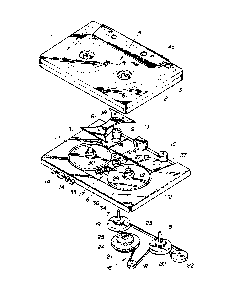
Fig. 1 is an overall exploded perspective view
of a preferred embodiment of a cassette type recording
and/or reproducing apparatus according to the present
invention;
Fig. 2 is an exploded perspective view of an
essential part of the cassette-type recording and/or
reproducing apparatus shown in Fig. l;
Fig. 3 is a top plan view of the essential
part of the cassette-type recording and/or reproducing
apparatus shown in Figs. 1 and 2;
Fig. 4 is a sectional view of the cassette-
type recording and/or reproducing apparatus taken along
line IV~IV in Fig. 3; and
Fig. 5 is a sectional view of the cassette-
type recording and/or reproducing apparatus taken along
line V-V in Fig. 3.
DETAILED DESCRIPTIO~ OF TH~ PREFERRED E~BOD M~TS
Reference will hereinafter be made to the
drawings in order to facilitate an understanding of the
present invention.
Figs. 1 through 5 show a cassette tape
recorder as a cassette-type recording and/or reproducing
apparatus to which the present invention is applicable.
The cassette tape recorder is an automatically-reversing
type of a dual capstan system using a compact cassette.
As shown in Fig. 1, a magnetic tape 3 wound on
a pair of reel hubs 1, 2 is housed in a cassette,
designated generally by the reference numeral 4. The
~ 4 ~ ~313259
cass2t~e 4 is ~orizontally mounted for recording and
playback or. an uppcr part of a chassis ~ cooperating
with reco-Aing and re?roducing compc~ents (not showm~ 25
a part o~ an overall ap~aratus. The chassis 6 is
structurally adapted to cooperate with a ~rive mechanism
for rotating the reel hubs for the respective tape reels
in the casset.~ in a forward or in a reverse direction,
at various speeds, to record and playback information on
the tape 3.
The upper part or top surface of the chzssis 6
contains a pa~r of left and right capstans 7, 8, pinch
rollers 9, 10, reel beds 11, 12, and a magnetic head 13.
The pair of lert and right reel hubs 1, 2 are
respectively engaged with the corresponding reel beds
11, 12. The ~agnetic tape 3 is extended through the
capstans 7, 8 and the magnetic head 13. A plurality of
operating buttons 14 for a play back or record mode, a
fast forward mode, a rewind mode, a stop mode, and so on
are attached to a side surface of the chassis 6 to
control the mode of operation of the cassette 4.
An actuation device 16 for actuating the pair
of capstans 7, 8 to rotate in mutually reverse
directions and for selectively actuating the pair of
reel beds 11, 12 is installed on a lower part or bottom
surface of the chassis 6. A change in thP direction of
rotation of the pair of reel beds 11, 12 is accomplished
by a gear change mechanism 17 installed at an
intermediate space between the reel beds 11, 12 and on
the upper part of the chassis 6. The gear change
mechanism 17 comprises a plurality of gears 27, ~8, 29
and 30.
When the playback butto~, included among the
buttons 14, is depressed with the cassette 4 mounted on
the chassis 6, the pinch roller 9 i5 pressed into
contact w 'h the capstan 7 a.,d the left reel bed 11 is
actuated to rotate in a counterclockwise direction.
`. ~ '~.!
,
. . .
131325q
-- 5 --
With the ma~net c tape 3 running normally to wind on the
left reel hub 1, a normal playback, or normal recording
is cause~ on the tape 3 by the magnetic head 13. When
the end of the tape 3 is reached during the normal run,
the pinch roller 9 is separated from the capstan 7~
After actuation of the reel bed 11 has ceased, the other
plnch roller 10 is pressed into contact with the other
capstan 8. At this time, the right reel bed 12 is
actuated to rotate in a clockwise direction and the
magnetic tape 3 runs in a reverse direction to wind on
the other or right reel hub 2. Consequently, a reverse
playback or a reverse recording is caused on the tape 3
by the magnetic head 13~ When a fast forward or a
rewind button among the operation buttons 14 is
depressed, a fast forward or rewind of the magnetic tape
3 is caused with the reel beds 11, 12 selectively
actuated to rotate at a high speed, i.e. at a speed
higher than used for normal or reverse recording or
playback.
The rotation actuation device 16, as shown in
Fig. 1, comprises a drive pulley 18 actuated by means of
a motor, to be described later, a pair of capstan
pulleys 19, 20 attached to a lower end of the capstans
7, 8, and a belt 23 wound about an intermediate pulley
21 and a direction change pulley 22~ A Fast Forward and
Rewind (FR) drive gear 24 is integrally and coaxially
mounted on an upper part of -the intermediate pulley 21.
Furthermore, a Normal and Reverse ~NR) drive gear 25
actuated via a torque limiter (not shown) is also
coaxially mounted on an upper portion of the FR drive
gear 24~ The gear change mechanism 17 is provided with
the Normal and Reverse (NR~ gears 27, 28 and Fast
Forward and Rewind (FR) gears 29, 30. A pair of reel
axles 31, 32 are respectively installed on the upper
portions of centers of the reel beds 11~ 12,
respectively. A pair of reel bed gears 33, 34 are
- 6 - 1 31 3259
-espectively lnstalled on the peripheries of the reel
beds 11, 12.
The structure of the chassis 6 and the
mounting states of the reel beds 11, 12 and gears 27
through 30 will be described with reference to Fig. 2
through Fig. 5.
A shown in Fig. 2, the chassis 6 is made of a
metallic plate. An upper surface 6a of the chassis 6
has a recess 36 substantially in the form OL an ellipse
(as best seen in Fig. 3) at substantially a center
portion of the upper surface 6d and another recess 37
substantially in the form of a trapezoid at a rear
portion of the upper surface 6a with respect to the side
surface on which the plurality of operating buttons 14
are mounted. These recesses are formed by a pressing or
drawing process. It should be noted that the recesses
36, 37 act to reinforce the chassis 6 so that the
chassis 6 becomes extremely rigid through the pressing
of the recesses 36, 37.
The reel beds 11, 12 and gears 27 through 30
are mounted on the upper portion of the chassis 6 and
within the recess 36 so as to be positioned on left and
right sides and at a center position within the recess
36. The upper surfaces lla, 12a of the reel beds 11, 12
and the upper surfaces 27a through 30a of the gears 27
through 30 are located at substantially the same level
as, or lower than, the upper surface 6a of the chassis
6, as can be seen in Figs. 2, ~, and 5. In addition,
a cover plate 38 (as best seen in Figs 1, 2, and 3),
substantially in a double concave shape, is screwed
substantially on the same plane as the upper surface 6a
of the chassis 6 at an upper portion o~ a center portion
of the recess 36, as seen in Fig. 5. The cover plate 38
is used to cover the above-described gears 27 through
30. The pair or capst2ns 7, 8 is moun_ed within the
rearward, generally-trapezoidal recess 37.
1 3 1 3259
As shown in Fig. 4, the reel bed 11 is
rotatably mou~ted on an outer periphery of z supporting
pole 40 which is installed on the upper portlon of the
recess 36 in the chassis 6. At this time, the reel bed
11 is inserted into the recess 36 with its center
opening penetrated by the supporting pole 40.
The other reel bed 12 is rotatably mounted on
an outer periphery of a supporting pcle 44 which is
installed on the upper portion of a casing 43 of the
motor 42 attached from a lower side of the chassis at an
opening 41 installed in the recess of the chassis 6. At
this time, the other reel bed 12 is inserted into the
recess 36 with its center hole penetrated by the
supporting pole 44. A suitable structure for the motor
42 is exemplified in the United States Patent
Application Serial No. 06/578,011 filed on February B,
1984 by the same applicants, which application
corresponds to the published United Ringdom Patent
Application Open No. 2,136,191-A.
As shown in Figs. 3 and 5, a supporting lever
47 is mounted on a supporting pole ~6 mounted coaxially
on an outer periphery of the NR drive gear 25 placed
below the chassis 6 so as to enable the lever 47 to
swing on the supporting pole 46. A supporting pin 48
installed on an upper portion of a tip of the supporting
lever 47 projects toward an upper portion oE the recess
36 ~rom the opening 49 of the recess 36 of the chassis
6. The NR gear 27 is rotatably supported on the outer
periphery of the supporting pin 48. At this time, the
one NR gear 27 is inserted into the recess 36 from the
upper direction of the chassis 6 during assembly. The
other NR gear 28 is rotatably supported on the outer
periphery of the supporting pin 50 fixed on the upper
portion of the recess 36 o~ the chassis 6, as seen in
Fi~s. 2 and 3. At this time, the other ~R gear 28 is
inserted onto the supporting pin 50 thereinto from the
- 8 - 13132sq
upper part of the chassis 6. The other NR gear 28 is
always -ngaged with the reel bed gear 33 of the one reel
bed 11. The one NR gear 27 can be engaged with or
disengased ~rom the other NR gear ~8 and reel.bed gear
34 of the other reel bed 12, while the one NR gear 27 is
alwavs engaged with the NR drive geax 25.
In addition, the FR gears 29, 30 are rotatably
mounted on mounting pins 53, 54 mounted on the lower
part of a tip of a supporting lever 52 arranged within
the recess 36 of the chassis 6. The supporting lever 52
is inserted onto a supporting pin 55 fixed on the upper
part of the recess 36 of the chassis 6 via an elongated
hole 56 during the assembly, is free to swing axound the
supporting pin 55 and is movable in the elongated
direction of the elongated hole 56. The FR gear 29
comprises a wide gear projected from the opening 57 of
: the recess 36 of the chassis 6 toward a lower direction
of the recess 36 and is detachably engaged with the reel
bed gear 34 of the reel bed 12 and the FR dxive gear 24.
In addition, the other FR gear 30 is always meshed with
the FR gear 29 so as to engage detachably with the reel
bed gear 33 of the one reel bed 11.
As shown in Figs. 2, 3 and 5, the cover plate
38 has three holes 59 each located substantially at a
vertex of an isosceles triangle formed by the cover
plate 38. On the other hand, on the upper part of the
recess 36, two supporting pins 50, 55 extend vertically
from the NR gear 28 and the elongated hole 56,
respectively, while another supporting pin 58 extends
vertically from the upper surface of the recess 36O In
addition, three female threaded holes 60 are provided on
upper central portions of the three supporting pins 50,
55, 58, respectively. When the screws 61 are fitted
into the corresponding female threaded holes 60 via the
correspondlng holes i9 in the cover plate 38, the cover
plate 38 is positioned horizontally with respect to the
recess 36 and detachably screwed to the chassis 6.
1 3 1 3259
_ 9 _
As shown in Figs~ 4 and 5, the cassette 4
denoted by a dot-and-dash line is mounted horizontally
on the ch2ssis 6. When the reel hubs l, 2 are engaged
wi~h the reel axles 31, 32 of the reel beds 11, 12 and
S the magnetic tape 3 is set so as to pass about the
capstans 7, 8 and in contact with the magnetic head 13,
the cassette 4 can be brought in close contact with the
upper surface 6a of the chassis 6. Consequently, the
entire tape recorder can be remarkably compacted
especially for its height. At this time, as shown in
Fig. 5, an extended portion 4a, which is
trapezoidally-shaped and located at the rear surface of
the cassette, is fitted to the recess 37 of the
chassis 6.
Since, in the above-described construction,
the reel beds ll, 12 and the plurality of gears 27
through 30 can be assembled on the upper portion of the
chassis 6 within the recess 36 from a single direction,
i.e. from above the upper part of the chassis 6, the
reel beds ll, 2 and gears 27 through 30 can be assembled
extremely simply. In addition, since a single cover
plate 38 can serve to prevent the N~ gears 27, 28
inserted from the upper direction and attached to the
supporting pins 48, 50 from drawing out toward the upper
direction as well as to prevent the FR gears 29, 30
inserted from the upper direction and attached to the
supporting pin 55 via the supporting lever 52 from
drawing out toward the upper direction, it is not
necessary to attach washers for preventing the gears
from drawing out toward the upper direction to the
individual upper ends of the supporting pins 48, 50, 55.
Hence, the number of parts to be used for assembl~ and
the labor ~ime required therefor can be reduced
remarkably. In addition, a mere removal o the single
c~ver plate 38 screwed to the upper surface of the
chassis can facilitate the replacement of the gears 27
through 30 and achieve better service.
, .,, ". .
1 31 325q
-- 10 --
The change of rotation in the dlrertion of the
reel beds ll, 12 by means of the gear change mechanism
17 will be described below with reference to Fig. 3.
When the magnetic tape 3 is in the normal
playback or record mode, the NR gear 27 is meshed with
the NR gear 28 as denoted by a solid line and the NR
drive gear 25 actuates the reel bed ll to rotate in a
counterclockwise direction as viewed from Fig. 3 via the
NR gears 27/ 28 and the reel bed gea 33. On the other
handl when the magnetic tape 3 is in a reverse playback
or record mode, the NR gear 27 is meshed with the reel
bed gear 34 as denoted by a dot and-dash line and the NR
drive gear 25 actuates the other .reel bed 12 to rotate
in a clockwise direction via the NR gear 27 and the reel
bed gear 34~ When the magnetic tape 3 is in the fast
forward mode, the FR gears 29, 30 are respectively
meshed with the FR drive gear 24 and reel bed gear 33 as
denoted by solia lines, and the F~ drive gear 24
actuates the one reel bed ll to rotate in the
counterclockwise direction via these gears 29, 30, 33 at
a high speed. When the magnetic tape 3 is in the rewind
mode, the FR gear 29 is meshed with the FR drive gear 24
and the reel bed gear 34 as denoted by the dot-and-dash
line, so as to actuate the other reel bed 12 to rotate
at a high speed via these gears 29, 34.
Since according to -the present invention
recesses are formed on the upper surface of the chassis
and the pair of left and right reel beds and associated
gears to actuate these reel beds are attached on the
upper surface of the one recess in a direction from
above the chassis, the cassette can be mounted on the
upper surface of the chassis with the entire surface of
the cassette brought in close contact with the upper
surface of the chassis. Consequently, the entire
cassette tape recorder of cassette-type recording and/or
reproducing apparatus can remarkably be compacted.
1 3 1 3 25 9
In addition, since the reel beds and g2ars can be
assembled only on the upper side of the chassis Lrom a
direction from above the chassis, the assembly OL the
reel beds and gears can be carried out in a very simple
manner as compared with the conventional structure in
which the reel beds and gea~s are assembled separately
on the upper and lower surfaces or the chassis.
Therefore, an easy assembly operation can be achieved.
The recesses formed on the upper surrace of the chassis
also provide a reinforcement structure for the chassis.
Therefore, the chassis becomes very rigid.
As described in the above embodiment, the
single cover plate 38 serves to prevent draw out of the
plurality of gears 27 through 30 so that the number of
parts to be used for the assembly of the cassette type
recording and/or reproducing apparatus and labor time
required to assembly can remarkably be achieved.
The present invention is applicable to the
other types of cassette type recording and/or
reproducing apparata such as cassette-type Video Tape
Recorders tVTR's) as well as to the cassette tape
recorder.
It will clearly be appreciated by -those
skilled in the art that the foregoing description is
made in terms of the preferred embodiment and various
changes and modifications can be made without departing
from the scope of the present invention which is to be
defined by the appended claims.