Note: Descriptions are shown in the official language in which they were submitted.
G~
1 31 4620
SPECIFICATION
TITLE OF THE I~ENTION
Multiplex TV signal processing apparatus
BACKGROUND OF THE INVENTION
1. Field of the Invention
This invention relates to an apparatus for multiplexing a
specific signal with an amplitude modulated television signal,
transmitting and receiving the multiplexed signal, and extracting
the specific signal from the, multiplexed signal.
2. Description of the Prior Art.
More than 30 years have passed since the color television broad-
casting of the current NTSC (National Television System Commit-
tee) system began in 1960. RecentLy, in search of finer defini-
tion and hi~her performance television system, several new sys-
tems including HDTV (High Definition Television) system developed
by NHK( The Japan broadcasting Corpora-tion) have been proposed.
At the same time, the contents of the programs presen-ted to
vie~ers have been changed from the mere studio programs to pro-
grams providing higher quality images and more realistic feeling
such as cinema-si~e movies.
The current NTSC broadcasting is standardized by 2:1 interlaced
c~
6 2 0
525 scanning lines, luminance signal bandwidth of ~.2MEz, and as-
pect ratio of 4:3. (See, for example, Pritchard, "US Color
Television Fundamentals -~ Review", I~EE Trans. Consumer Elec-
tron.~ vol. CE-23, pp.467-478, Nov. 1977.)
In this background, several television slgnal composition
methods aiming at compatibility with the current broadcasting
system and enhancement of horizontal resolution have been pro-
posed. One of such examples is presented in a paper of Fukinuki
and Hirano, "Extended Definition TV Fully Compatible with exist-
ing Standards", IE~E Trans. Commun., vol. COM-32, pp.948-953,
Aug. 1984. Considering the NTSC television signal expressed on a
t~o-dimensional plane of temporal frequency fl and vertical fre-
quency f2, chrominance signals C are present in the second and
fourth quadrants due to the phase relations to the chrominance
subcarrier fsc. The Fukinuki et al example uses the vacant first
and third quadrants or multiplexing the high frequency com-
ponents of luminance signal. The chrominance signal and the mul-
tiplex high frequency components are separated and reproduced at
the receiving end, thereby enhancing the horizontal resolu-tion.
In this example, the conventional NTSC receiver would be inter-
ered by the multiplex signal, because the example has no ability
for separating the chrominance signal from the multiplex high
frequency components.
In the current television broadcast, as clear from the descrip-
tion above, signal bandwidth is limited by the standard, and it
is not easy to add some new information in good quality. For ex-
! 6 ~ ~
ample, other methods to enhance the horizontal resolution are
proposed (M. Isnrdi et al, "A single Channel NTSC Compatible
Widescreen EDTV System", HDTV Colloquim in Ottawa, Oct., 1987),
but many problems are left unsolved from the viewpoint of the
compatibility with the current television broadcasting and
deterioration of demodulation characteristics of high frequency
components in a moving picture. Besides, from the standpoint of
effective use of the frequency resources, the transmission band
cannot be extended as an easy way.
The present inventors have previously invented a method of
superposing a signal by using quadrature modulation of the video
carrier. (U.S. Patent No. 4,882,614) By this method, various
signals can be transmitted using newly established ~uadrature
channel and the interference to the conventional NTSC receiver is
very small in principle. But the interference can be detected in
practice, because of the incompleteness of characteristics of
filters at the receiver and transmitter.
This invention is on~ of solutions to this practical problem
when quadrature modulation is carried into practical use. Even
if the incompleteness of such circuits as filters occurs, the
interference to the conventional NTSC receivers can be reduced
down to the acceptable level. In this sense, this invention is
very useful when ~uadrature modulation of the video carrier is
implemented.
SUMMARY OF THE INVENTION
@-- ~
1 31 4620
It is a primary object of this invention to provide a multiplex
signal processing apparatus for multiplex transmission of a large
~uantity of information in a limited bandwidth without interfer-
ence to the current receiver.
According to this invention, a multiplex signal processor at a
transmitter side replaces hidden portions of the main NTSC signal
(the portions which are not displayed on a screen by over-
scanning of a receiver) and front porch of horizontal synchronous
signal of the main NTSC signal uith a first specific multiplex
signal, amplitude-modulates a main video carrier by the main sig-
nal to obtain a vestigial side band (VSB) signal, and amplitude-
modulates a carrier which is same in frequency as and shifted in
phase by 90 degrees from the main carrier by a second specific
multiplex signal to obtain a double side band signal. The modu-
lated multiplex signal is passed through an inverse Nyqùist
filter to obtain a vestigial side band (VSB) signal, and then su-
perposed on the modulated main signal to obtain a multiplexed
signal, which is transmitted.
A multiplex signal processor at a receiver side has a synchro-
nous detector and a quadrature distortion eliminating filter for
demodulating the main and multiplex signals from the multiplexed
signal received.
~ y this constitution, it is possible to obtain not only the con-
ventional television broadcasting images but also multiplex in-
formation at the receiver, by generating a television signal ca-
1 3 1 Ll 6 2 0
pable of multiplex trans~ission of o-ther information within the
standard band of the existing television broadcasting.
As an example, if side panels (signals which correspond to -the
left and right sides of a whole image) of a wider aspec-t picture
than the conventional 4:3 are transmitted as the first and second
multiplex signals, the ~ider aspec-t picture can be generated at a
receiver end from the main signal(4:3 NTSC) and the multi21ex
signals(side panels). In this case, low and high frequency com-
ponents of the side panels can be transmitted as the first and
second multiplex signal, respectively. DC component of -the first
multiplex signal can be easily transmitted, so as to keep con-
tinuity between the side panels and center panel ( signal which
corresponds to the ~:3 aspect ratio image). On the other hand,
the second multiplex signal can be easily scramoled to reduce the
interference to the conventional receivers.
3y employing the above mentioned techniques, when the multiplex
signal is received by an e~isting television receiver, -there is
almost no interference by the mul-tiplex signal. In other words,
-the compatibility with the existing television receivers c~n be
main-tained. Furthermore, the fea-ture that multiplex transmission
of other information is possible in a fre~uency band determined
by the standard is very advantageous also from the viewpoi.nt of
effec-tive use of frequency resources.
BRIEF DESCRIPTIO~T OF THE DR~WINGS
1 3 1 4 62()
Fig. 2, Fig. 12 ~a), Fig. 16(a), and Fig. la(a) are block di-
agrams each showing a multiplex signal processor at the transmis-
sion side embodying this inven-tion;
Fig. 4(c), Fig. 12(b~, Fig. 18(b), and Fig. 16(b) are block di-
agrams each showing a multiplex signal processor at the reception
side embodying this invention;
FigsO 1 (a)-(c) and Figs. ll(f)-(j) are spectral diagrams show-
ing the processing method OI the multiplex signal processor at
the transmission side according to this invention;
FigO 4~a) is a spectral diagram showing the processing method of
the multiplex signal processor at the reception side according to
this invention;
EigO 4(b) is a vector diagram to explain the principle of the
multiplex signal processor at the reception side according to
this invention;
. .
Figs. 3(a), (~), and (c) are block diagram, spectral diagram,
and vector diagram s~o~ing a conventional television receiver
. _ ~ .. . .
when receiving the composite signal generated by the mul-tiplex
signal processor;
Fig. 5 shows wave forms to explain the function of the signal
separator;
Fig. 6 is a block diagram of the signal separator;
Figs. ll(a)-(e) are signal waveform diagrams showing the signal
processing steps in Fig. 6 according to this invention;
Fig. 7 is a block diagram of the signal composer;
Fig. a is an example of display screen of existing television
¢ - -
~31~62~
and a time-axis e~pression of composite video signal;
Fig. 9 is an example of display screen with aspect ratio of 5:3
and time-axis expression of composite video signal;
FigO 10 is a picture composi-tion at different aspect ratio;
Fig. 13(a) is an internaL circuit composition of a signal gen~
erator 125 in Fig. 12(a);
Fig. 13(b) shows an example of discriminating signal;
Fig. 14 is an internal circuit composition of a signal separator
131 in Fig. 12(b),
Fig. 15 is an internal circui. composition OI a signal selector
137 in Fig. 12tb).
Figs. 17(a) and (c) are block diagrams of IWo e~amples of the
scramblerO
Fig. 17(b) is a figure to explain the scrambled picture.
DETAIL~D DESCRIPTION OF THE PREFERRED EMBODIMENTS
Figs. 1 ta)- (c) are spec-tral diagrams to show a television sig-
nal processing method at the transmission side. More specifical-
ly, Fig. lta) is a spectral diagram of a vestigial side band, am-
plitude modulated television signal in the NTSC television sys-
tem, in which the lower side band of a video carrier P1 is the
vestigial side band. In this case, the signal may be an~ -televi-
sion signal amplitude rnodulated, and thus it is not limited to
the NTSC television slgnal.
Fig. l(b) is a spec~rum of a signal which is obtained by ampli-
1 3 1 ~ ~20
tude modulating a multiplex signal by a carrier P2 which is same
in frequency as and different in phase by 90 deyrees from the
video carrier Pl and passing the modulated signal -through a spe-
cial filter which is called "inverse Ny~uist filter". The fre-
~uency characteristic of the inverse Nyquist filter is -6dB at
frequenc~ P2, infinite attenuation at P2+1.25MHz, and no attenua-
tion at P2-1.25MHz. Preferably, the carrier P2 is removed in the
blanking period of the main television signal.
The signal shown in Fig. l~b) is multiple-~ed with the main
television signal shown in Fig. l(a) to obtain a composite signal
as shown in Fig. l(c). The multiplex signal may be either analog
signal or digital signal.
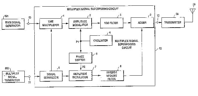
Fig. 2 is a block diagram showing a television multiplex signal
processor at the transmission side as an embodiment of this in-
vention. A main signal generator 601 genera~es a main signal
such as a video base band signal. A multiplex signal generator
602 generates a multiplex signal which is either analog or digi-
tal signal. The main and multiplex signals are fed -to a multi-
plex signal superposing circuit 13 through input terminals 10 and
11, respectivel~l.
In the multiplex signal superposing circuit 13, the multiplex
signal is separated at a signal separator 6 into two parts, one
of which is multiplexed with the main signal at a time multipler
1, and the other is amplitude-modulated at an amplitude modulator
7.
~ig. 5 shows the function of the time multiplexer 1 in the case
l3~ .a
that -the main signal is the video base band signal. In Fig. 5, a
wave form (a) shows a composite video base band signal with a
horizontal synchronous signal and a burst signal of chrominance
subcarrier, (b) shows a multiplex signal from -the signal separa-
tor 6, and (c) shows a time multiplexed signal which is outputted
from the time multiplexer 1~ In this case -the multiplex signal
from -the signal separator 6 is multiplexed at the hidden portions
of over-scanning and front porch of hori~ontal synchranous signal
of the main video base band signal. By the main signal coming
from the time mul-tiplexer 1, the video base band signal multi-
plexed with a part of multiplex signal, a carrier Pl generated by
an oscillator 4 is amplitude- modulated at an amplitude modulator
2. The obtained modulated signal is filtered by a VSB filter 3
to become a vestiaial side band signal, which is fed to an adder
9. The VSB filter 3 is a filter to transform a dcuble side band
signal into a vestigial side band signal. The carrier Pl from
the oscillator 4 is shifted in phase by 90 degrees a-t a phase
shif-ter 5 to be a carrier P2.
Fig. 6 shows an example of the signal separa-tor 6.
In Fig. 6, -the multiplex signal generated by the multiplex sig-
nal generator 602 is fed to a low-pass filter 610 and a subtrac-
tor 611. Low frequency component of the multiplex signal from the
low-pass filter 610 is fed to a time compression circui-t 612 and
the subtrac-tor 611. The low frequency component is time-
compressed at the time compression circuit 612 and fed to the
time multiplexer 1. On the other hand, high frequency component
1 3 1 4 ~21~)
of the multiplex signal is ob-tained at -the subtractor 611 and
time-expanded at a time expanding circuit 613 to a narrower
bandwidth signal, which is fed to the amplitude modulator 7. In
this example, the input multiplex signal is separated by its fre-
quency. Alternatively, any other attribute such as an amplitude
and time of the input signal can be a factor of the signal
separator.
Referring back to FigO 1, by one of the two parts of the mul-ti-
plex signal separated by the signal separator 6, the carrier P2
is amplitude-modulated in double side band at the amplitude modu-
lator 7, and preferably in the blanking period the carrier is
suppressed. The phase shift direc~ion of the phase shifter 5 may
be either fixed or varied at intervals of horizontal scanning
period, field or frame. The modulated multiplex signal is limit-
ed in the band by an inverse ~yquist filter 8, and then fed to
the adder 9. The amplitude rrequency charac-teris~ic of the in-
verse Nyquist filter 8 is symmecrical to an amplitude frequency
charactsristic immediately before video detection at -the receiver
with respect to the video carrier.
The output of the adder 9 is a composite signal. That is, the
modulated multiplex signal is su~erposed on the modulated video
base band signal at the adder 9 to obtain the composite signal.
The composite signal appearing at an output terminal 12 of the
multiplex signal supe:rposing circuit 13 is transmitted from a
transmitter sa with an an-cenna 59. The transmission path is not
limited to the wireless sys-tem, but may be a wired system. In
1 0
1 3 1 L!7~20
this example, the composite signal is obtained by adding the out-
puts of the VS~ filter 3 and the inverse Nyquist fil-ter 8, but it
is also possible to feed the sum of the outputs of the amplitude
modulator 2 and the inverse Myquist filter 8 into the VSB filter
3 to obtain the composite signal.
On the other hand, a television multiplex signal processor at
the reception side is as follows. The following example refers
to terrestrial broadcasting of the NTSC television system, but is
is not intended as limitation. Fig. 3(a) is a blocl~ diagram of
an e~isting television receiver with a synchronous video detec-
tor. The signal transmitted from the transmission side is re-
ceived by an antenna 21, converted in frequency to an intermedi-
ate frequency band by a tunner 22, and limited in the band by a
Nyquist fil-ter 23. The band-limited signal is fed in-to a video
detector 24 and a carrier regenerator 25. In the carrier regen-
erator 25, the video carrier I1 or synchronous detection is re-
generated. The band-limited signal is synchronously detected by
the carrier I1 at the video detector 24 to obtain the main sig-
nal, that is the video base band signal, at an output terminal
26.
The frequency characteristic of the Nyquist filter 23 is as fol-
lows. Referring to Fig. 3(b) which shows the frequency charac-
teristic of the Nyquist filter 23, the amplitude is attenuated by6dB at the video carrier I1, and the Nyquist filter characteris-
tic possesses nearly an odd~symmetrical amplitude property with
respect to the video carrier I1.
1 3 i ~620
On the other hand, as shown in Fig. l(b), when the multiplex
signal is limited in band by the inverse Nyquist filter 8 in the
transmitter having an inverse characteristic to the frequency
characteristic of the Nyquist filter 23 in the receiver, the mul-
tiplex signal components in the shaded area in ~ig. 3(b) is near-
ly double side band. This can be expressed by a vector diagram
as shown in Fig. 3(c), in which Il is the video carrier of the
main signal, tha-t is, the video base band signal, and I2 is the
carrier of the multiplex signal which carrier is same in frequen-
cy as but dif erent in phase by 90 degrees from Il. The video
base band signal is a vestigial side band with respect to the
carrier Il, so that the upper and lower side bands are vector aU
and vector aL, respectively, which are Veclor al and vector a2,
respectively, when decomposed into orthogonal vectors. Since the
upper and lower side bands of the multiplex signal are expressed
by vector bU and vector bL, respectively, their synthetic vector
is b2, which is only the component to intersect with vector Il
orthogonally.
That is, when the main signal is synchronously de-tected by the
carrier Il, quadrature distortion due to the vector a2, vector b2
components does not occur. Thus, the impairment by the multiplex
signal to the existing television receiver performing video syn-
chronous de-tection does not occur in principle.
Next, detection of the multiplex signal at the reception side is
described below. The signal of the video intermediate frequency
band which is the output of the tuner 22 is limited in band by a
1314~
band-pass filter, as shown in ~ig. 4(a), so that the main signal,
that is, the video base band signal, becomes double side band.
Its vector expression is shown in Fig. 4(b). Since the multiplex
signal is vesticTial side band, the upper and lower side bands are
vector bU and vector bL, respectively, their synthetic vector is
al, which is only the component intersecting orthogonally with
the vector I2.
That is, ~hen the multiplex signal is synchronously detected by
the carrier I2, quadrature distortion due to the vector al, vec-
tor bl components does not occur. Thus, oniy the multiplex sig-
nal components can be demodulated.
Fig. 4(c) shows an example of television multiplex signal pro-
cessor for demodulating the multiplex signal as ~ell as the main
signal. The multiplexed signal transmitted from the transmission
side is received by an antenna 31, converled in frequency into an
intermediate fre~uency band by a tuner 32, and fed to a multiplex
signal separator 44 through an input terminal 41 thereof. The fed
signal is limited in the band by a ~Tyauist filter 33. The band-
limited signal is ~ed to a video deteclor 34 and a carrier regen-
erator 35. In the carrier regenerator 35, the video carrier Il
for synchronous detection is regenerated. The band-limited sig-
nal is synchronously detected by the carrier Il in the video
detector 34, and fed to a time demultiplexer 36. In the time
demultiplexer 36 the main signal and the first multiplex siynal
are separated. This processing is just the opposite to that of
the time multiplexer 1 in the multiplex signal superposing cir-
1 3 1 L'l ) 2 0
cuit 13 at the transmission side. The first multiplex signal isfed into a signal composer 40 and the main signal, -the base band
video signal, goes to an ou-tput terminal 42 of the multiplex si~-
nal separator 44.
The main signal is converted into, for example, R, G, B sisnals
by a main signal processor 603, and displayed on a CRT screen
1000 .
The output of the tuner 32 is band-limi-ted also as shown in rigO
4(a) b~ a band-pass filter 37. By the carrier I2 obtained by 90
degrees phase shifting the carrier I1 by a phase shifter 3a (that
is, by the carrier I2 in the same phase as the carrier for mul~i-
plex signal modulation used at the transmission side), the band-
limited signal is synchronously detected in a multiplex signal
detector 39 to obtain the second multiplex signal. The second
multiplex signal is composed into the original multiplex signal
together with the i-irst multiplex signal a-t the sisnal composer
40.
Fig. 7 shows an example of the signal composer 40. In this fig-
ure, the first multiplex signal from the time demultiple:rer 36 is
time-expanded at a time expansion circuit 401. The second multi-
plex signal from the muLtiplex signal de-tector 39 is added to the
time-expanded first multiplex signal at an adder 402. The com-
posed multiplex signal, which is the output of the adder 402, is
fed to an output terminal 43 of the multiplex signal separa~or
44. In the multiplex signal generator 604, the composed multi-
plex signal is subjected to the reverse processing to the pro-
1 3 1 4 ~20
cessing by the multiplex signal generator 602 at the transmissionside.
As described above, in the existing receiver, since the multi-
plex signal is substantially canceled by the synchronous detec-
tion by the video carrier I1, the main signal is not interfered
by the multiplex signal. Further, in the recsiver capable of
demodulating the multiplex signal, not onl~ the main signal, that
is, the video base band signal, is obtained in the same way as
above, but also the multiplex signal can be also obtained without
quadrature distortion by filtering and synchronous detaction by
the carrier I2. This is not limited to the ~TSC television sys-
tem, and can be applied to any system as far as the main signal
is amplitude-modulated in the vestigial side band.
Fig. 8 and Fig. 9 show the conce?t of a wide-screen television
system. In these figures, the as~ect ratio of the wide-screen
television system is assumed to be 5:3 bu~ it may not be limited
to such ratio. In Fig. 8, the present NTSC picture (a) and its
corresponding wave form (b) are depictad, in which a circle and 2
arcs are displayed on the 4:3 frame. Fig. 9 shows 5:3 picture
(a) and its corresponding wave form (b), in which 3 circles are
displayed. Only when we see 5:3 picture in Fig. 9, 3 circles are
recognized. For this purpose of clear recognition, side panels
should be transmitted as the multiplex signal.
Fig. 10 shows the difference between the aspect ratios of the
conventional NTSC system and the wide-screen television system.
In this figure, (s) means side panels which is treated as one
-- 15--
1 31 4620
signal and transmitted as the multiplex signal and (M) means
c~nter panel which corresponds to the present 4:3 frame (the main
signal).
These side panels and cen-ter panel have the same frequency band,
but the band width of the mul-tiplex signal should be, at most,
1.25MHz according to the above explana-tion. Figs. 11 (a)-(j)
show wave forms and power spectrums of various points of the
signal separator 6 in Fig. 6. Fig. ll(a) is the multiplex signal
which corresponds to the two parts of side panels. Fig. ll(f)
shows a typical power spectrum of the above multiplex signaln
First, the input multiplex signal (Fig. ll(a)) is fed to the
low-pass filter 610, where the low freauency component (Fig.
ll(b) shows its wave form and (g) shows its power spectrum) is
obtained. This signal is time-compressed at the time compression
circuit 612 which bandwidth is increased up to that of the origi-
nal signal. Fig. ll(c) shows this time-com~ressed signal and (h)
shows its power spectrum. On the other hand, the high frsauenc~
component (Fig. ll(d) shows its wave forn and (i) shows its power
spectrum ) is obtained at the subtractor 611. This signal is
time-expanded at the time expanding circuit 613. Fig. 11 (e)
shows the wave ~orm o-f -the time-expanded signal and (j) shows its
bandwidth which is, at most, 1.25~Hz.
Thus, the multiplex signal is subjected to time-a;~is processing
to be separated to two parts, one of which is transmitted through
the main channel replacing the hidden portion of over scanning
and front porch of synchronous signal, and the other is transmit-
1 3 1 4~2'J
ted through ~uadrature modulation of the video carrier.
Fig. 12(a) is a block diagram showing a television multiplexsignal processor with a wide aspect ratio at the transmission
side. In Fig. 12(a), the signal fed to an input terminal 111 is
a luminance siynal Y obtained from a signal picked up by a camera
having a wider aspect ratio (for instance, 16:9) than the exisl-
ing one, the signal fed to an input terminal 114 is a wide band
chrominance difference signal I obtained from the same picked-up
signal, and the signal fed to an input terminal 117 is a narrow
band chrominance
The luminance signal Y enters a signal distributor 112, to be
distributed into a time-axis expanding circuit 113 and an adder
123. Similarly, the wide band chrominance difference signal
and the narrow band chromlnance signal Q enter respective signal
distributors 115 and 113, to be distributed into time-axis ex-
panding circuits 116 and llg, respectively, and a balanced modu-
lator 122. EacA of the time-axis expanding circuits tlme-expand
the entered signal by, for example, varying the writing and read-
ing clocks of a memory provided therein.
When the original picture is picked up at an aspect ratio of m:3
(m is a real number not smaller than 4 ) stretcned laterally, the
picked-up signal corresponding to the portion displayed on the
screen of the existing television receiver is expanded in the
time-axis by m/4 times in the time-axis expanding circuits 113,
116, 119.
~ext, of the chrominance difference signals distributed by the
--17-
1 31 462a
signal distriDutors 115, 118, the remaining chrominance differ-
ence signals other than those expanded by the time-axis expandinc
circuits 116, 119 are modulated by the halanced modula-tor 122 r
and are combined with the remaining luminance component other
than the luminance signal expanded by the time-axis expanding
circuit 113 by the adder 123. The output of the adder 123 is fe(l
into the multiplex signal superposing circuit 13 through the mul-
tiplex signal input terminal 11 as a multiplex signal.
The output signals of the time-axis expanding circui-ts 116, 119
are modulated by a halanced modulator 120, and the outpu-c of -the
balanced modulator lZ0 is added by an adder 121 to the output
signal from the time-axis expanding circuit 113 and a synchronous
signal, a burst signal and a discriminating signal which are pro-
duced at a signal generator 125. The discriminating signal is
for distinguishing -the composite television signal of this pro-
cessor from the conventional television signal. The discriminat-
ing signal may be, for example, superposed in the vertical blank-
ing period.
The ou-tpu-t of the adder lZ1 is fed into the multiplex signal su-
perposing circuit 13 through the main signal input terminal 10 as
a main signal. The output of the multiplex signal superposing
circuit 13 appearing at the terminal 12 is a composi-te signal in
which the multiplex signal is superposed on the video base band
main signal. The composite signal is transmitted -through -the
transmitter 58 and the antenna 59.
Fig. 13(a) is a block diagram of the signal genera-tor 125 in
-18-
1 31 4~20
Fig. 12(a~, in which a synchronous signal generator 126 and a
burst signal generator 127 generate a synchronous signal and a
burst signal, respectively, which are the same as those in the
conventional broadcasting system.
A discriminating signal generator 12a generates a discriminating
signal to distinguish whether a picture o~ the wide aspec-t ratio
is sent out or not. The discriminating signal is, for example, a
pilot signal OI the like superposed in -the blanking period as
shown in Fig. 13(b). The sum o~ the outputs of these three gen-
erators 126, 127, 12a, is delivered as an output from t~e signal
generator 125.
Fig. 12(b) is a block diagram showing a television multiplex
signal processor with a wide aspect ratio at the reception sideO
The composite signal transmitted from the transmission side like
~he one as shown in ~ig. 12~a) and received via an antenna 31 and
a tuner 32 is separated at a multiplex signal separator 44 into
the main signal and the multiplex signal, which are respectively
delivered from a main signal output terminal 42 and a multiplex
signal output terminal 43 of the multiplex signal separator 44.
The video base band signal which is the main signal is separated
in-to the luminance signal Y and the chrominance signal C by a ~C
separator 132. The signal Y is compressed in the time-axis by a
time-axis compression circuit 134 to become a signal Y1. The
signal C is separated into the chrominance difference signals I,
Q by an I,Q demodulator 133. The signal I is compressed in the
time-a-xis by a time-axis compression circuit 135 to become a sig-
--19-
4620
nal I1. The signal ~ is compressed in the time-axis by a time-
axis compression circuit 136 to become a signal Q1. The multi-
plex signal is compressed in the time-axis by a time-axis
compression circuit 138, and then is separated into siynals Y2~
I2 and Q2 by a YC separa-tor 139 and an I,Q demodulator 140. The
signals Y1, I1, Q1, Y2, I2 and Q2 are fed into a signal selector
137, in which the signals Y1, I1 and Q1 are selected -for the por-
tion corresponding to the center panel of the conventional telev-
ision receiver with aspect ratio of 4:3. For the remainina por-
tion of one horizontal scanning period, the blanking signal or
the like is generated and selected when receiving the convention-
al television signal, and the signals Y2, I2 and Q2 are selected
when receiving said wide television sisnal. A matrix circuit 141
produces R, G, B signals from the selected signals outputed from
the signal selector 137. The R, G, B signals are fed into the
CRT 1000.
Incidentally, the time-axis compression circuits 13~1, 135, 13O,
138 are provided to receive the convenlional -television signal
without any trouble, and to reproduce the television signal by
compressing the time-axis expanded portion of the wide television
signal having an aspect ratio stretched laterally. That is, as
clear from the comparison between Fig. 8~b) and Fig. 9(b), it is
necessary to compress the time-acis of the conventional televi-
sion signal in order to receive the picture o-f the existing
broadcasting without changing the aspect ratio. The compression
ratio is determined by the aspect ratio.
-20-
131462n
The signal separator 131 separatest from the video base band
signal, the discriminating signal for distinguishing the televi-
sion signal of the existing broadcasting from the synchronous
signal, color burst signal, and the wide television signal. The
signal selector 137 is controlled according to this discriminat-
ing signal.
Fig. 14 is a block diagram of the signal separator 131 in Fig~
12(b), which comprises a gate circuit 144. The video base bancl
signal which is the main signal is fed to the gate circuit 144.
The discriminating signal is separated from -the video base band
signal by the gate circuit 144. Since the discriminating signal
is superposed, for example, in the blanking period of the video
base band signal, its separation is easy.
Fig. 15 is a block diagram of the signal selector 137 in Fig~
12(b). If it is judged that the received signal is not ~or a
picture with wide aspect ratio by the discriminating signal, the
signals Y1, I1 and ~1 are selected by selec~ors 1~5 and 147, and
a blanking signal generated by a blanking signal generator 14a is
selected in the blanking period. If it is judged tha-t the re-
ceived signal is for a picture with wide aspect ratio by the
discriminated signal, the signais Y2, I2 and ~2 are selected by
the selectors 146, 147.
The signal expanded in the time-axis is widened in the band when
it is time-axis-compressed at the reception side, and therefore
the resolution is not lowered even if the aspect ratio becomes
larger. The multiplex signal not appearing on the screen of as-
-21-
~-.~
1 3~ 4i~)20
pect ratio of 4:3 is nearly canceled in the conventional receiver
by synchronous detection using the video carrier, so that in-
terf~rence by the multiplex signal hardly occurs. In the
widescreen receiver, the multiplex signal containing video signal
to be displayed on the side portions of a wide aspect ratio
screen is reproduced by filtering and synchronous detection using
the phase-controlled carrier without quadrature distortion. When
the television signal having the conventional asoect ratio of 4:3
is received, it is displayed near the middle of the screen OI as-
pect ratio of 5:3, and the both sides of the screen are, Eor ex-
ample, blanked.
Fig. 16(a) is a block diagram OI another multiplex sisnal pro-
cessor at the transmission side. The difference be~ween Fig. 2
and Fig. 16(a) is the presence of a scrambler 51. The main func-
tion of this scrambler is to reduce the interference to the con-
ventional television receiver uith an envelope video detector or
quasi-synchronous video detec-tor caused by the quadrature modula-
tion by the multiplex signal. This scrambler is also used to use
wide-screen television system as a pay television. There are many
methods of scrambling, such as frequenc~ inver-ting, time-axis in-
verting, e~changing line(s) by line(s), changing left side panel
and righ-t side panel, changing polarity of the multiplex signal
line by line, and changing polarity of the multiple~ signal field
by field.
A multiplex signal generated by the multiplex siynal generator
60~ is fed to the signal separator 6 and separated , for example,
1 3 1 4` 6 ~ O
by frequency to two parts. The first part, low frequency com-
ponent, of the multiplex signal is fed to the time multiplexer 1
and processed as described before, and the second par-t, high fre-
~uency component, of the multiplex signal is fed -to -the scrambler
51.
Fig. 17(a) shows a block diagrarn of a first example of the
scrambler 51. In this example, the input multiplex signal is
stored in a frame memory and retrieved therefrom according to a
control signal from a timing generator 514. The multiplex sig-
nal, normally high frequency component, comes to -two frame store
buffers 511 and 512, and retrieved therefrom according to the
control signal from the timing generator 514. The control signal
is superposed in the vertical blanking period of the multiplex
signal, for example.
Fig. 17(b) shows a displa-~ screen of scrambled multiplex signal.
The left screen is the original multiplex signal at the input of
this scrambler and the right screen is the ou-tpu~ of the scram-
bler. In this example, the original multiplex signal is separat--
ed into three parts which are transposed wi-thin a field or frame.
With the same block configuration as -that shown in Fig. 17(a),
other scramble rnethod sucn as exchange of the left side and right
side, polarity change line by line and so on, can be possible
only if the ad~ress to frame buffers is changed.
Fig. 17(c) is another example of the scrambler 51 in Fig. 16(a).
In this example, the input multiplex signal is fed to a modulator
515 and modula-ted by a subcarrier fs from a subcarrier generator
2 0
517. rrhis modulator may be an amplitude modulator and fs rnay be
fsc/3 (fsc: subcarrier of chIominance si~nal, 3.5795~5MHz). The
modulated multiplex signal is fed to a band-pass filter 516. In
this case, if fs is about l.ZMHz and the pass-band frequenc~ of
the band-2ass filter 516 is from 0.16MHz to 1.2~Hz at -6d~
points, the output signal from the band-pass filter is jus-t fre-
quency inverted to the original multiplex signal.
The power spectrum of the original multiplex signal is just like
the one shown in Fig. ll(j), so the inverted multiplex sisnal has
lower power at low fre~uency componenl and higher power at high
frequency component.
From the spectral diagram shown in Eig. 3(b), the power of the
quadrature multiplex signal at an existing television receiver is
low at higher component and high at lower component. From this
reason, the effect of this example is that the possible cross~alk
to an existing receiver from the multiplex channel is smaller
than the original superposing circuits in Fig. 2.
In the example shown in Fig. 17(c), subcarrier fs is superpos2d
on the multiplex signal at a superposer 513, for exampLe, in the
vertical synchronous period, in order to descramble at the recep-
tion side.
Fig. 16 (b) is a block diagram o-f a multiplex signal processor
at the reception side for receiving the multiple~ed signal
transmitted -from the transmission side such as the one shown in
~ig. 16(a). The multiplexed signal transmitted from the
-transmission side is received by the antenna 31, conver-ted in
-24-
1 3 ~ '~ 6 ,` ~3
fre~uency into the intermediate frequency band by the tuner 32,
and limited in the band by the ~Jyquist ~ilter 33. The band-
limited signal is supplied into the video detector 34 and the
carrier regenerator 35. In the carrier regenerator 35, a video
carrier Il for synchronous detection is regenerated. The band~
limited signal is detected by the carrier Il in the video detec-
tor 34, and fed to the time demultiple~er 36. In this demulti-
plexer the main signal and the first multiplex signal are
separated. The first multiplex signal is, for example, superposed
in the hidden portion of over scanning of -the television recei~er
and/or the front porch of the horizontal synchronous signal~
This processing is just the opposite of those of the time mul_i-
plexer 1 in -the multiplex signal superposing circuit 13 a-t the
transmission side shown in Fig. 16 (a). The second multiplex
signal is fed into a descrambler 52 and descrambled. This pro-
cessing is just the opposite to that a~ the scramnler 51 of the
transmission side and per~ormed according -to the superpose~d con-
trol signal, for example, the signal showing which line(s) is
transposed to which line(s). After -the multipls~ signal is
descrambled at the descrambler 52, it is fed in~o the signal com-
poser 40 and composed with the first multiplex signal. Finally,
-the composed multiplex signal goes to the output terminal 43.
Fig. la(a) shows a block diagram of still another multiplex sig-
nal processor at the -transmission side. This figure shows another
version of the multiplex signal superposing circuit 13 uhich per-
forms an alternative ~uadrature amplitude modulation. By chanq-
-25-
1 31 ~S2(~
ing the polarity of amplitude modulation line by line, or field
by field, the interference to an existing television receiver is
reduced, or at least it becomes less sensitive to vie~ers. In
Fig. 18(a), an amplitude modulator 55 is added and a selector 56
switchs modulated signals Erom the amplitude modulator 7 and the
amplitude modulator 2 according to the defined seqùence.
Fig. 18(b) sho~s a bloc~. diagram of a multiplex signal processor
at the reception side for receiving the multiplex signal generzt-
ed by the processor such as the one shown in Fig. 18(a). This
figure shows another version of the multiplex signal separator 44
which includes an alternative detector. By detecting the
amplitude-modulated signal as a positive modulation or a negative
modulation alternatively, the multiplex signal is success~ully
demodulated. The modulated signal from the band-pass filter 37
is fed to both of a multiplex signal detector 39 and a multiplex
signal detector 57 and detected.
The generated carrier I2 is fed to both of the two multiplex
signal detectors 39, 57. The detected multilex signals, one of
which is positive and another is negative, are fed to a selector
5a and selected according to the defined sequence. This sequence
is either to be transmitted as a ~ontrol signal or -to be generat-
ed within the reception side.
From the selector 5a, the original multiplex signal is outputed
and processed as mentioned be~ore.
When the multiplex signal has no DC component, negative and po-
sitive modulations are performed by changing the polarity of the
c~
1 31 ~620
original multipLex signal- Changing the polarity of tAe multi-
plex signal and changing the polarity of the carrier is und~r-
stood to be equivalent.
_ _ .~ . ._ ...................................... .... , .. __ . __ .__.
... .