Language selection

Search

Patent 1314693 Summary

Third-party information liability

Some of the information on this Web page has been provided by external sources. The Government of Canada is not responsible for the accuracy, reliability or currency of the information supplied by external sources. Users wishing to rely upon this information should consult directly with the source of the information. Content provided by external sources is not subject to official languages, privacy and accessibility requirements.

Claims and Abstract availability

Any discrepancies in the text and image of the Claims and Abstract are due to differing posting times. Text of the Claims and Abstract are posted:

  • At the time the application is open to public inspection;
  • At the time of issue of the patent (grant).
(12) Patent: (11) CA 1314693
(21) Application Number: 1314693
(54) English Title: FERRITE CORE PLACEMENT METHOD AND APPARATUS
(54) French Title: METHODE DE MISE EN PLACE DE NOYAU MAGNETIQUE ET DISPOSITIF CORRESPONDANT
Status: Expired and beyond the Period of Reversal
Bibliographic Data
(51) International Patent Classification (IPC):
  • G11B 5/105 (2006.01)
  • B23Q 3/154 (2006.01)
  • B25B 27/14 (2006.01)
  • G11B 5/48 (2006.01)
  • G11B 5/60 (2006.01)
(72) Inventors :
  • KATZ, MARAT GREGORY (United States of America)
  • GORI, GINO EGIDIO (United States of America)
(73) Owners :
  • SEAGATE TECHNOLOGY INTERNATIONAL
(71) Applicants :
  • SEAGATE TECHNOLOGY INTERNATIONAL (United Kingdom)
(74) Agent: SMART & BIGGAR LP
(74) Associate agent:
(45) Issued: 1993-03-23
(22) Filed Date: 1988-11-24
Availability of licence: N/A
Dedicated to the Public: N/A
(25) Language of filing: English

Patent Cooperation Treaty (PCT): No

(30) Application Priority Data:
Application No. Country/Territory Date
154,819 (United States of America) 1988-02-11

Abstracts

English Abstract


ABSTRACT OF THE DISCLOSURE
A method and apparatus for placing a ferrite core in
the slot of a pad of a ferrite head. A circular magnet is
mounted below a non magnetic table on a slider slidable
along a line. The pad is clamped on the table with its slot
exposed and aligned along the line and the center of the
magnet. When the ferrite core is placed on the table near
the magnet, it stands on edge, aligned along a radial line
of flux from the magnet. As the magnet is slid towards the
slot, the core follows the center of the magnet, aligned
along the centerline of the slot following the radial line
of flux. The core slides into the slot and is thereafter
bonded to the pad.


Claims

Note: Claims are shown in the official language in which they were submitted.

THE EMBODIMENTS OF THE INVENTION IN WHICH AN EXCLUSIVE
PROPERTY OR PRIVILEGE IS CLAIMED ARE DEFINED AS FOLLOWS:
1. A method of placing a magnetic workpiece in a slot of a
second non magnetic workpiece comprising the steps of
mounting below a non magnetic table a circular magnet
with its center slidable along a line;
clamping a second workpiece having a slot on the table;
with said slot exposed and its centerline aligned
with said line and the center of the magnet;
placing said first magnetic workpiece on the table
adjacent the magnet; and
sliding the magnet towards the slot thereby moving and
aligning the first magnetic workpiece along the
slot centerline until it enters the slot.
2. A method of placing a ferrite core in a slot of a pad
of a ferrite head comprising the steps of
mounting below a non magnetic table a circular magnet
with its center slidable along a line;
clamping a head pad having a slot on the table; with
said slot exposed and its centerline aligned with
said line and the center of the magnet;
placing a ferrite core on the table adjacent the
magnet; and
sliding the magnet towards the slot thereby moving and
aligning the ferrite core along the slot
centerline until it enters the slot.
- 5 -

3. Apparatus for orienting and placing a magnetic workpiece
in a slot of a second workpiece comprising:
a non magnetic table;
a slider mounted below said table and slidable along a
line;
a circular magnet mounted on said slider with the
center of the magnet located on said line; and
means for clamping a second workpiece having a slot on
said table, with the slot exposed and its
centerline aligned with said line and the center
of the magnet;
said circular magnet having a magnetic field
sufficient to cause said first workpiece to be
moved along said centerline as the slider slides
along said line, with the degree of motion along
said line sufficient for said magnet to move said
first workpiece into the slot of the second
workpiece.
4. The apparatus of claim 3 wherein said first workpiece
is a ferrite core and said second workpiece is the
pad of a ferrite head.
- 6 -

Description

Note: Descriptions are shown in the official language in which they were submitted.


1 ~ 3 ~
1 F~RRITE CO~ ~LACEM~ T~OD AND APP~RAT~8
2 1. FIELD OF THE INVENTION
3 The invention relates to manipulating small workpieces
4 and more particularly ts placing ferrite cores into the pads
of ferrite heads.
6 2. BRIEF DESCRIPTION OF THE PRIOR ART
7 The prior method of placing ferrite cores into the slot
8 of the pad of a ferrite head has been to grasp the ferri~e
9 core with a pair o~ tweezers and, with the aid of a
microscope or magnifying glass, manually orient the core and
ll place it into the slot. Ferrite heads are primarily
12 utilized in magnetic recording, especially disk drives.
13
14 ~U~M~RY OF T~E INV~NTION
It is an object of this invention to provide a method
16 and apparatus for placing magnetic cores into the pads of
17 magnetic heads by sliding the core into the slot using a
18 moving magnet.
19 This object is achieved by providing a circular magnet
below a non magnetic table with its center slidable along a
21 line of motion, placing a pad haviny a slot with a
22 centerline onto a table with its slot exposed and centerline
23 aligned with the line of motion and the center of the
24 magnet, placing a ferrite core on the table near the magnet,
whereupon the core stands up on edge under the influence of
26 the magnet's magnetic field, and sliding the magnet towards
27 the pad, moving the now vertically aligned core into the

~ 3 ~ 3
1 slot. The invention encompasses the placement of a magnetic
2 workpiece into the slot of another workpiece.
4 BRIEF DE~CRIPTION OF T~E D~A~INGS
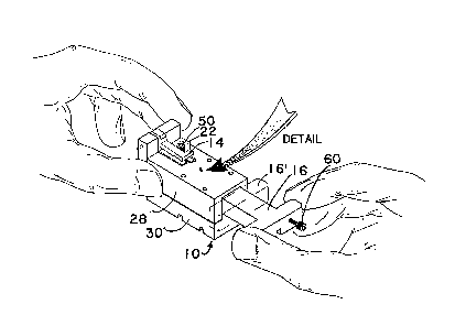
Fig. 1 is a perspective view of a apparatus according
6 to the present invention.
7 Fig. 2 is a detail of the ferrite core and pad from
8 Fig. 1.
9 Fig. 3 is a front plan view of the apparatus.
Fig. 4 is a top plan view of the apparatus.
11 Fig. 5 is a side plan view of the apparatus.
13 DE8ClRIPTION OF q~l~l3 PREF:E:RRED E~lBOl~ ENT
14 Fig.s 1-5 show the preferred apparatus and method of
positioning a magnetic core into a slot of a pad. The
16 apparatus 10 comprises a magnet 18 located on a slider 16.
17 (Fig.s 3 - 5) Slider 16 is located between upper 28 and
18 lower 3 0 members of apparatus 10l and preferably has a
19 retainer (not shown) for preventing the slider from being
entirely withdrawn from the apparatus 10.
21 Nest 22 with clamp 14 holds the pad onto table 24 with
22 the pad's slot 26 exposed and aligned with its centerline
23 aligned with the center of magnet 18.

:~ 3 ~ 3
1 All materials of the apparatus lO, except magnet 18,
2 are non magnetic.
3 When a magnetic core 32 is placed on the table 24 near
4 the magnet, the magnetic field of the circular magnet causes
the core to stand on edge as shown in the figures. When the
6 slider is pushed towards the pad 14, it moves the core 32
7 with it. The coxe follows $he magnet aligned in the
8 direction of motion. Because a circular magnet's flux
9 fields are radial, the core tends to align with the magnetic
field along a radial. The moving motion gradually causes
11 the core to move to align along the radial in the direction
12 of motion. As magnet's center is mounted along the
13 centerline of the pad's slot, it eventually moves the core
14 into the slot. No other orientation or placement is
required.
16 Also shown in Fig. 1 are a set screw 50 which may be
17 loosened to adjust the pad nest 22 so that the slot 26 of
18 pad 12 i5 in perfect alignment along the center of the
19 magnet. As well, a stop screw 60 is provided to terminate
the motion of the slider 16 at a position 16', after the
21 core is fully placed in the slot. The magnetic field of the
22 magnet is useful to hold the core in place in the slot
23 during subse~uent operations wherein the core is bonded to
24 the pad. The set and stop screws are not shown in
subsequent figure~.
26 Fig. 3 is a front plan view of the apparatus lO. In
27 this figure magnet 18 i5 visible, mounted on slider 16 just
28 below table top 24. Also shown in the figure (in phantom
29 line) is a runner 20 for guiding the motion of the slider
16. The other elements shown in the figure have previously
31 been discussed. They are clamp 1~, pad 12 having a slot 26
32 aligned on the center of the magnet lB by pad nest 22, and
33 upper 28 and lower 30 members of apparatus 10.
- 3 -

1 Fig. 4 is a top plan view of the apparatus showing in
2 phantom line the other portions of slider 16 not heretofore
3 visible and circular magnet 18~ When moving the core 32
4 towards slot 26, the core, as above discussed, follows the
center of the circular magnet 18 along a radial line of
6 flux.
7 Figure 5 is a side plan view of apparatus 10. This
8 view snows the other elements previously discussed and as
9 well the runner 20 upon which slider 16 runs and is guided.
As well, the figure shows the handle of clamp 14, which
11 pivots on rod 15. The clamp shown in the figure is a simple
12 lever. The invention contemplates more elaborate clamps,
13 including cams, etc. It is important to note in this figure
14 that core 32 trails the center of circular magnet 18.
While the description of the embodiment of this
16 invention pertains to particular materials and structures,
17 the invention is not restricted to these particular
18 materials and structures. It is unders -d that other
19 arrangements may be devised with the scope of the invention.

Representative Drawing
A single figure which represents the drawing illustrating the invention.
Administrative Status

2024-08-01:As part of the Next Generation Patents (NGP) transition, the Canadian Patents Database (CPD) now contains a more detailed Event History, which replicates the Event Log of our new back-office solution.

Please note that "Inactive:" events refers to events no longer in use in our new back-office solution.

For a clearer understanding of the status of the application/patent presented on this page, the site Disclaimer , as well as the definitions for Patent , Event History , Maintenance Fee  and Payment History  should be consulted.

Event History

Description Date
Inactive: IPC from MCD 2006-03-11
Time Limit for Reversal Expired 1998-03-23
Letter Sent 1997-03-24
Grant by Issuance 1993-03-23

Abandonment History

There is no abandonment history.

Owners on Record

Note: Records showing the ownership history in alphabetical order.

Current Owners on Record
SEAGATE TECHNOLOGY INTERNATIONAL
Past Owners on Record
GINO EGIDIO GORI
MARAT GREGORY KATZ
Past Owners that do not appear in the "Owners on Record" listing will appear in other documentation within the application.
Documents

To view selected files, please enter reCAPTCHA code :


To view images, click a link in the Document Description column. To download the documents, select one or more checkboxes in the first column and then click the "Download Selected in PDF format (Zip Archive)" or the "Download Selected as Single PDF" button.

List of published and non-published patent-specific documents on the CPD .

If you have any difficulty accessing content, you can call the Client Service Centre at 1-866-997-1936 or send them an e-mail at CIPO Client Service Centre.


Document
Description 
Date
(yyyy-mm-dd) 
Number of pages   Size of Image (KB) 
Cover Page 1993-11-10 1 13
Claims 1993-11-10 2 54
Abstract 1993-11-10 1 17
Drawings 1993-11-10 4 69
Descriptions 1993-11-10 4 126
Representative drawing 2002-03-28 1 12
Examiner Requisition 1992-02-20 1 49
Prosecution correspondence 1992-05-14 2 50
PCT Correspondence 1992-12-31 1 20
Fees 1996-02-14 1 35
Fees 1995-02-02 1 73