Language selection

Search

Patent 1314721 Summary

Third-party information liability

Some of the information on this Web page has been provided by external sources. The Government of Canada is not responsible for the accuracy, reliability or currency of the information supplied by external sources. Users wishing to rely upon this information should consult directly with the source of the information. Content provided by external sources is not subject to official languages, privacy and accessibility requirements.

Claims and Abstract availability

Any discrepancies in the text and image of the Claims and Abstract are due to differing posting times. Text of the Claims and Abstract are posted:

  • At the time the application is open to public inspection;
  • At the time of issue of the patent (grant).
(12) Patent: (11) CA 1314721
(21) Application Number: 1314721
(54) English Title: LEVELING MECHANISM FOR TRIPOD BASE
(54) French Title: MECANISME DE MISE AU NIVEAU POUR BASE DE TREPIED
Status: Expired and beyond the Period of Reversal
Bibliographic Data
(51) International Patent Classification (IPC):
  • A47G 23/02 (2006.01)
  • F16M 07/00 (2006.01)
  • F16M 11/20 (2006.01)
(72) Inventors :
  • HASTINGS, THOMAS C. (Canada)
(73) Owners :
  • THE COLEMAN COMPANY, INC.
(71) Applicants :
  • THE COLEMAN COMPANY, INC. (United States of America)
(74) Agent: HAROLD C. BAKERBAKER, HAROLD C.
(74) Associate agent:
(45) Issued: 1993-03-23
(22) Filed Date: 1989-05-03
Availability of licence: N/A
Dedicated to the Public: N/A
(25) Language of filing: English

Patent Cooperation Treaty (PCT): No

(30) Application Priority Data:
Application No. Country/Territory Date
249,701 (United States of America) 1988-09-27

Abstracts

English Abstract


LEVELING MECHANISM FOR TRIPOD BASE
Abstract of the Disclosure
A leveling mechanism is provided for a campstove which
includes a base and a plurality of legs which are pivotally
attached to the base. The leveling mechanism is a ring-shaped
band which is inserted between the legs and the base. A camming
ramp extends over a portion of the circumference of the band and
progressively increases the thickness of the band. The band is
rotatable to position the camming ramp between one of the
pivoting legs and the base for pivoting the leg away from the
base,


Claims

Note: Claims are shown in the official language in which they were submitted.


THE EMBODIMENTS OF THE INVENTION IN WHICH AN EXCLUSIVE
PROPERTY OR PRIVILEGE IS CLAIMED ARE DEFINED AS FOLLOWS:
1. A leveling mechanism for a base having a plurality
of legs pivotally attached to the base, the leveling mechanism
comprising a ring-shaped band, means for securing the band on the
base, and a camming ramp on the band which extends over a portion
of the circumference of the band for increasing the thickness of
the band, the thickness of the band being substantially uniform
except in the area of the camming ramp.
2. The leveling mechanism of claim 1 in which the band
is segmented and includes a pair of opposed end portions, said
securing means comprising means for holding the opposed end
portions together.
3. The leveling mechanism of claim 2 in which said
securing means comprises a pin which extends from one of the
opposed end portions of the band through the other opposed end
portion.
4. The leveling mechanism of claim 1 in which the band
has a frusto-conical shape and includes a circular lower edge and
a circular upper edge which has a larger diameter than the lower
edge.
5. In combination, a base having a plurality of legs
pivotally attached to the base and a leveling mechanism,
each of the legs having a pivot portion which is
pivotally attached to the base and a stop portion which is
engageable with the base for maintaining the leg in a supporting
position,
the leveling mechanism comprising a ring-shaped band
having a camming ramp which extends over a portion of the
circumference of the band for increasing the thickness of the
band, the band being rotatably mounted on the base and positioned
between the base and each of the stop portions of the legs,

whereby the camming ramp can be rotated into engagement with one
of the stop portions to pivot said one stop portion away from the
base.
6. The structure of claim 5 in which the base and the
band each have an inverted frusto-conical shape,
7. The structure of claim 5 in which the band is
segmented and includes a pair of opposed end portions, and a pin
which extends from one of the opposed end portions through the
other opposed end portion whereby the band is releasably mounted
on the base.
8. The structure of claim 7 in which the pin is molded
integrally with said one opposed end portion.
9. The structure of claim 5 in which the length of the
camming ramp is less than the distance between adjacent legs so
that the camming ramp cannot engage more than one leg at a time
and can be positioned between adjacent legs so that the camming
ramp does not engage any leg.

Description

Note: Descriptions are shown in the official language in which they were submitted.


_c~
This invention relates to a leveling mechanism for a
tripod base. The invention en~oys particular utility with a
campstove which has three pivoting legs. It will be understood,
however, that the leveling mechanism can be used with other
products. Further, the leveling mechanism can be used with bases
which include four or more legs, and the term Wtripod~ as used
herein is not meant to be limited to a three-legged support.
A campstove, particularly a backpacking campstove, is
of~en used on rugged terrain. Such terrain i~ usually not 1QVe1
and it is often difficult to make the stove stand upriaht. I~
the burner asse.nbl~ of the stove is not level, the cooking
utensil which is supported on the stove is apt to fall off. In
that event, the user could ~e injured by hot liquid or food, and
the meal could be lost or rende~ed inedible.
summ~ry of the Invention
The leveling mechanism consists of a ring-shaped band
whic~ is sized to fit between the pivoting legs of a campstove
and the base of the campstove. A camming ramp extends over
portion of the circumference of the band and progressively
increases the thickness of the band. The band is rotatable to
pGsition a desired portion oE the camming ramp between one of ;he
legs and the base. The camming ramp pivots the leg and changes
the inclination of the leg celative tO the other legs, t~lereby
lowering the oottom of the leg.
Description of the Drawing
The invention will be explained in conjunction with an
illustrative embodiment snown in the accompanyin~ drawing, in
which --
Fig. 1 is a perspective view of a campstove;
; _ 1 _

- 1 31 ~721
Fig. 2 is a perspective view of a leveling band for use
with the campstove;
Fig. 3 is a top plan view of the leveling band~
~ ig. 4 is a bottom plan ~iew of the levelin.~ band;
Fig. 5 is a perspecti.ve ~iiew .showing the leveling ~and
being positioned on the campstove;
Fig. 6 is a perspective view showing the leveling band
being adjusted;
Fig. 7 is a fragmentary side elevational view showing
all three legs of the campstove in a level position;
Fig. 8 is a fragmentary elevational view showing the
leveling band rotated to pivot one of the legs below the other
two legs;
Fig. 9 is a fragmentary sectional view taken along the
line 9-9 of Fig. 7; and
Fig. 10 is a fragmentary sectional view ~aken along the
line 10-10 of Fig. 8,
Description of Specific ~mbodiment
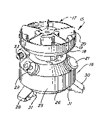
Referring to Fig. 1, a campstove 15 includes a base 16
and a burner assembly 17. The particular campstove illustrated
is a compact single burner stove which is suitable for use by
backpackers.
The burner assembly 17 includes a reflector bowl 18, a
burner box 19, and a plurality of grids 20 which are adapted to
support a cooking utensil such as a pot or a pan. The base 16
provides a fuel tank, and a fill spout for the tank is closed by
a cap 21. The tank is pressurized by a hand pump 22, and fuel
flow to the burner box is controlled by a valve 23.
The base i~,cludes a cylindrical side wall 25, a
frusto-conical wall 26 which conveLges downwardly, and a ~lat
bottom wall 27 (Fig. 8). Three support legs 28, 29, and 30 are
pivotally attached to the frusto-conical wall 26 by U-shaped
--2--

1 ~ 1 r 7 2 1
brackets 31. Each bracket includes a bight portion 32 (Figs. 9
and 10) which is spotwelded to the frusto-conical wall and a pair
of end portions 33 A pin 34 extends through the end portions
and through the leg ~or pivotally securing the leg.
Each leg includes a foot portion 35 which engages the
supporting surface and a stop portion ~6 (Figs. 9 and 10) which
engages the frusto-conical wall 26. In the particular embodiment
illustrated, the stop portions 36 are V-shaped, and the foot
portions have a serrated bottom surface. When the legs are in
their supporting position as illustrated in Fig. 1, the stop
portions of the legs engage the frusto-conical wall, and the legs
e~tend angularly outwardly from the base at an angle relative to
~he vertical centerline or axis of the campstove.
The campstove which has been described is conventional
and was available prior to the invention of the leveling
mechanism which is described herein.
The leveling mechanism comprises a ring-shaped band 38
(Figs. 2-4). The band is segmented or split and includes a pair
of opposed end portions 39 and 40 which extend radially
outwardly A pin 41 is molded integrally with the end portion 3~3
and is adapted to be snapped into an opening in the end porticn
40 to hold the opposed end portions together.
The band 38 is generally frusto conical and includes a
circular top edge 42, a circuiar bottom edge 43 which has a
smaller diameter than the top edge 42, and inside surface 44
which is adapted to mate with the frusto-conical wall 26 of the
campstove, and an outside surface 45. The thickness of the band
is uniform over a major portion of its circumference, but the
ou~side surface 45 extends outwardly away from the top and bottom
edges to form a camming ram~ 46. The camming ramp includes top
and bottom walls ~7 and 48 which extend outwardly from th~ top
and bottom edges 42 and 43, respectively, and generally radially
--3--

1 3 ~ ;7 ~ 1
extending end wall 49O The band may be injected molded in one
piece from plastic.
The leveling band is mounted on the campstove by
positioning the band around the frusto-conical wall 26 of the
campstove as shown in Fig. 5. The legs 28-30 can be pivoted away
from the wall 26 to permit the band to be positioned between the
stop portion 36 o~ the legs and the wall 26. The opposed end
portions 39 and 40 are pulled together, and the pin 41 is snapped
through the opening in the end portion 40 to retain the band
around the campstove. The band can rotate relative to the
frusto-conical wall 26, and the brackets 31 prevent the band from
slipping downwardly away from the frusto-conical wall.
The arcuate length of the camming ramp 46 is less than
the length of the arcs between the legs 28-30. The band can
therefore be positioned so that the camming ramp is between
adjacent legs and does not engage any legs as shown in Fig. 7.
In that position the portion of the band having constant
thickness is positioned between the frusto-conical wall 26 and
the stop portion 36 o~ each of the legs 28-30. Each leg
therefore extends at the same angle relative to the vertical axis
or centerline of the campstove, and the campstove will be
maintained level when the supporting surface S is level as
illustrated in Fig. 7.
When the supporting surface S is uneven as illustrated
in Fig. 8, the leveling band is rotated to bring the camming ramp
46 into engagement with the stop portion 36 o~ one of the legs.
In Fig. 8 the camming ramp engages the leg 28 and causes that leg
to pivot downwardly so that its foot portion 35 is below the foot
portions 35 of the legs 29 and 30. The vertical distance between
the foot portion of the leg 28 and the foot portions of the other
legs can be adjustea as heeaea ~y rotatlng the camming ramp. The
legs 29 and 30 engage portions of the supporting surface which
have the same elevation, and the position of the leg 28 is
adjusted to level the campstove.
--4--

7 ~ 1
While the invention has been described in combination
with a campstove, it will be understood that the leveling band
can be used with other devices which are supported by pivoting
legs. A detailed description of a specific embodiment of the
invention has been set forth for purposes of illustration, but
many of the details herein given may be varied considerably by
those skilled in the art without departing from the spirit and
scope of the invention.

Representative Drawing
A single figure which represents the drawing illustrating the invention.
Administrative Status

2024-08-01:As part of the Next Generation Patents (NGP) transition, the Canadian Patents Database (CPD) now contains a more detailed Event History, which replicates the Event Log of our new back-office solution.

Please note that "Inactive:" events refers to events no longer in use in our new back-office solution.

For a clearer understanding of the status of the application/patent presented on this page, the site Disclaimer , as well as the definitions for Patent , Event History , Maintenance Fee  and Payment History  should be consulted.

Event History

Description Date
Time Limit for Reversal Expired 2008-03-25
Letter Sent 2007-03-23
Inactive: IPC from MCD 2006-03-11
Inactive: CPC removed 2001-05-18
Inactive: CPC assigned 2001-05-18
Grant by Issuance 1993-03-23

Abandonment History

There is no abandonment history.

Fee History

Fee Type Anniversary Year Due Date Paid Date
MF (category 1, 5th anniv.) - standard 1998-03-23 1998-03-04
MF (category 1, 6th anniv.) - standard 1999-03-23 1999-03-10
MF (category 1, 7th anniv.) - standard 2000-03-23 1999-12-22
MF (category 1, 8th anniv.) - standard 2001-03-23 2000-12-27
MF (category 1, 9th anniv.) - standard 2002-03-25 2002-01-24
MF (category 1, 10th anniv.) - standard 2003-03-24 2002-11-04
MF (category 1, 11th anniv.) - standard 2004-03-23 2003-10-28
MF (category 1, 12th anniv.) - standard 2005-03-23 2004-11-04
MF (category 1, 13th anniv.) - standard 2006-03-23 2006-02-06
Owners on Record

Note: Records showing the ownership history in alphabetical order.

Current Owners on Record
THE COLEMAN COMPANY, INC.
Past Owners on Record
THOMAS C. HASTINGS
Past Owners that do not appear in the "Owners on Record" listing will appear in other documentation within the application.
Documents

To view selected files, please enter reCAPTCHA code :


To view images, click a link in the Document Description column. To download the documents, select one or more checkboxes in the first column and then click the "Download Selected in PDF format (Zip Archive)" or the "Download Selected as Single PDF" button.

List of published and non-published patent-specific documents on the CPD .

If you have any difficulty accessing content, you can call the Client Service Centre at 1-866-997-1936 or send them an e-mail at CIPO Client Service Centre.


Document
Description 
Date
(yyyy-mm-dd) 
Number of pages   Size of Image (KB) 
Claims 1993-11-09 2 57
Abstract 1993-11-09 1 14
Drawings 1993-11-09 2 71
Descriptions 1993-11-09 5 161
Representative drawing 2000-08-13 1 10
Maintenance Fee Notice 2007-05-06 1 172
Fees 1997-03-04 1 28
Fees 1996-02-19 1 29
Fees 1995-02-09 1 27
PCT Correspondence 1989-08-14 1 36
Courtesy - Office Letter 1989-08-01 1 74
Courtesy - Office Letter 1989-11-16 1 16
Courtesy - Office Letter 1990-04-09 1 16
Courtesy - Office Letter 1990-11-06 1 18
Courtesy - Office Letter 1992-10-22 1 14
Prosecution correspondence 1992-06-22 1 26
PCT Correspondence 1992-11-08 1 26