Note: Descriptions are shown in the official language in which they were submitted.
13149(~5
BACKGROUND OF THE INVENTION
Field of the Invention
This invention relates to an optical head of
an optical recording and reproducing device for
optically carrying out the recording and the repro-
duction of in~ormations or either of them.
Description of the Prior Art
An optical head is disclosed, for example,
in Japanese Utility Model Appln. Laid-Open No.
142829/1985. In that Utility Model, a housing member
for housing a light source, an optical detector and the
like are shown with the housing member being provided
with a guide hole formed therein, and the guide hole
being provided with a cylindrical holder, which is
provided with at least one optical element fixedly
disposed thereon, movably engaged therewith in the
axial direction. A fixing screw is screwed in a tapped
hole which is a through hole formed in the housing
member whereby the holder is fixed to the housing
member.
The holder is put in the guide hole. Then,
the holder is moved in the axial direction to be posi-
tioned so that the optical element, which is fixedly
disposed on the holder, may be disposed at the
appointed position determined in view of the optical
design. Finally, the fixing screw is screwed into tha
tapped hole to fix the holder.
-- 1 --
~314'~ 5
Usually, accurac~ of micron order is
required for the positioning of the optical element.
Howevex, since the pointed end of the fixing screw i5
in general unevenly shaped, with the above-described
conventional optical head, when the fixing screw is
screwed up, the position, at which the holder is first
engaged with the fixing screw, does not come on the
central axis of the fixing screw, whereby the holder is
moved by the fixing screw until the appointed value of
torque, at which the rotation of the fixing screw is
stopped, is obtained. Accordingly, the conventional
optical head has a problem in that it is difficult to
dispose the optical element, which is fixedly disposed
on the holder, at the appointed position.
SUMMARY OF THE INVENTION
The present invention was achieved for
solving the above-described problem. In the optical
head according to the present invention, a tapped hole
is not a through hole reaching a guide hole but an
opening with a bottom portion left and a fixing screw
having a conical end is provided which is screwed into
such a tapped hole and the end of the screw presses the
bottom portion to deform the same causing the deformed
portion to engage the holder and thereby fix the holder
to the housing member.
Thus, it is a first object of the present
invention to provide an optical head capable of easily
-- 2
. ~, '
1 3 1 4935
fixedly disposing an optical element, which is fixedly
disposed on a holder, at an appointed position.
It is a second object of the present
invention to provide an optical head without requiring
readjustment since the holder, which has finished the
positional adjustment of the optical element, is not
moved when fixed.
An optical head, in accordance with the
present invention, i5 provided with a housing member
for housing a holder, which holder is provided with an
optical element which is fixedly disposed in a light
path between a light source and an optical detector and
is movable in the direction of an optical a~is in a
guide hole formed therein. ~he optical head is
provided for condensing a light from the light source
onto a medium, condensing a re~lected light ~rom the
medium onto the optical detector and detecting the
reflected light by the optical detector. The optical
head is characterized in that the housing member is
provided with a tapped hole formed in a direction
meeting substantially at right angles with the axial
direction from a surface 50 as not to reach the guide
hole -to leave a bottom portion having a thickness such
that a screw screwed into the tapped hole fi~es the
holder to the housing member by pressing a circum-
ference of the holder.
The above and further objects and features
of the invention will more fully be apparent from the
3 -
1 3 ~ 5
following detailed description with accompanyingdrawings.
BRIEF DESCRIPTION OF THE DRAWINGS
Fig. 1 is a perspective view showing
principal parts of the conventional optical head;
Fig. 2 is an enlarged sectional view showing
principal parts o~ the conventional optical head;
Fig. 3 is a sectional view showing an
optical head according to the present invention;
Fig. 4 is an enlarged perspective view
showing principal parts of an optical head according to
the present invention; and
Fig. 5 is an enlarged sectional view showing
principal parts of an optical head according to the
present invention.
DESCRIPTION OF THE PREFERRED EMBODIMENTS
Fig. 1 and Fig 2 are a perspective view and
a sectional view, respectively, showing the principal
parts of the conventional optical head disclosed, for
example, in Japanese Utility Model Appln. Laid-Open No.
14282g/1985. Referring now to Figs. 1 and 2, reference
numeral 1 designates a housing member for housing a
light source, an optical detector and the like (not
shown) therein, the housing member 1 being provided
wlth a guide hole 2 formed therein, and the guide hole
2 being provided with a cylindrical holder 3, which is
provided with at least one optical element ~not shown)
fixedly disposed thereon, movably engaged therewith in
;
1 3 1 1~ 9 i 1 ~1
the axial direction. And, a fixing screw 4 is screwed
in a tapped hole 16 which is a through hole formed in
the housing member 1, whereby the holder 3 is fixed to
the housing member 1.
Next, the procedure for fixing the holder 3
to the housing member 1 is described.
At first, the holder 3 is put in said guide
hole 2. Then, the holder 3 is moved in the axial
direction to be positioned so that the optical element,
which is fixedly disposed on the holder 3, may be
disposed at the appointed position determined in view
of the optical design. Finally, the fixing screw 4 is
screwed into the tapped hole 16 to fix the holder 3.
Usually, accuracy of micron order is
required for the positioning of the optical element.
However, since the pointed end of the fixing screw 4 is
in general unevenly shaped, with the above-described
conventional optical head, when the fixing screw 4 is
screwed up, the position, at which the holder 3 is
first engaged with the fixing screw 4, does not come on
the central axis 4a of the fixing screw 4, whereby the
holder 3 is moved by the fixing screw 4 until the
appointed value of torque, at which the rotation of the
fixing screw 4 is stopped, is obtained, as shown in
Fig. 2. Accordingly, the conventional optical head has
a problem in that it is difficult to dispose the
optical element, which is fixedly disposed on the
holder 3, at the appointed position.
- ~a -
1 3 1 ~ 5
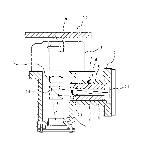
Fig. 3 is a sectional view showing an
optical head according to the present invention, and
Fig. 4 is a partial perspective view shawing the
optical head shown in Fig. 3. Referring to Figs. 3 and
4, reference numeral 1 designates a housing member
provided with a guide hole 2 formed therein~ reference
numeral 8 designating an actuator, and reerence
numeral 10 designating a medium. The housing member 1
is provided with a light source 7 disposed on an opened
portion thereof, a prism 14 serving as a half mirror
and a lens 13 for turning a light from the light source
7 into a parallel light bein~ disposed with optical
axes thereo~ coincided with each other, and an
objective lens 9 for condensing the parallel light from
the lens 13 onto the medium 10 to form an image being
housed in the actuator 8.
The housing member 1 is provided with an
optical detector 11 for detecting a reflected light
from the medium 10 on the opened portion of the side on
which the guide hole 2 is
- ~b -
1 3 1 4 9 ~ ~
formed therein, and a cylindrlcal holder 3 provided with a
lens 12 for condensing the reflec-ted light from the medium
10 onto the optical detector 11 fixedly disposed thereon be-
ing put in the guide hole 2 so as to be movable in the a.~ial
direction. The housing member 1 is provided with a tapped
hole 6 formed on the circumference of -the guide hole 2 not
so as to reach the guide hole 2, in short, so as to leave a
bottom portion 5 having -the appointed -thickness and a fixing
screw 4 is screwed into said tapped hole 6 to fix the holder
3 in the guide hole 2 of the housing member 1.
Next, the optical path in such an optical head is de-
scribed.
~ light emi-tted from the light source 7 is passed
through -the prism 14 to be turned into a parallel light by
means of the lens 13 followed by focusing on the medium 10
in the form of a condensed spot by means of the objective
lens 9 disposed within the actuator 8. The light focused on
the medium 10 is reflec-ted and then turned into a parallel
light by means of the objective lens 9 followed by bein~
condensed by means of -the lens 13 alld reflected by the prism
1~ to change a course thereof by 90 . The light reflected
by the prism 1~ is collected onto the optical detector 11 by
means of the lens 12.
In this time, it is necessary to adjust the position of
the lens 12 so tha-t the ligh-t led to the optical detector 11
1 31 ~5
may be accurately focused on the optical detector 11. And,
since the lens 12 is fixedly disposed on -the holder 3, the
holder 3 is fixed to the housing member 1 and then -the posi-
tion of the lens 12 is finally determined.
Next, the method of determining the posi-tion of the
lens 12 and the method of fixing the holder 3 in the optical
head according to the presen-t invention are described with
reference to Fig. 5 in detail showing the fixed condition.
At first, the holder 3 is moved in the axial direction
to adjust the position of the lens 12 so -that the light -to
led to the optical detector 11 may be accurately focused on
-the optical detector 11. After finishing the posi-tional ad-
justment of the lens 12 the fixing screw 4 is screwed up
along the tapped hole 6 provided in the housing member 1.
Thus, since the tapped hole 6 is formed with the bottom por-
tion 5 left, the bottom portion 5 of the tapped hole 6 is
deformed as the fixing screw 4 is screwed up to some extent
and the deformed bottom portion 5 is pressed by the fixing
screw 4, whereby the holder 3 is fixed to the housing member
1 (refer to Fig. 5).
As above described, according to the present invention,
since the holder 3 is pressed by the fixing screw ~ throu~h
the bottom portion 5 of the tapped hole 6 when the holder 3
is fixed to -the housing member 1, the torclue of rotation
generated when -the fixing screw 4 is rotated is absor~ed in
131~9~5
the bottom por-tion 5 of -the -tapped hole 6, whereby only the
fastening force is transmitted to the holder 3. Thus, the
holder 3, of which posi-tional adjustment of -the lens 12 was
finished, is not. moved when fixed, so -that the position of
the optical element is not changed and the optical element
can be easily disposed at the appointed position. Accord-
ingly, it is unnecessary to readjust the position of tne
holder 3.
In addition, although the lens 12 for condensing a
light onto the optical de-tector 11 is fixedly disposed on
the holder 3 in the above described preferred embodiment,
the construction is not limited by this. The lens 13 for
turning the light from the light source 7 into a parallel
ligh-t may be fixedly disposed on the holder ~. .
In addition, in the cases where other optical elements,
such as 1/2 wavelength plate, 1/4 wavelength plate and re-
fractive lattice, are housed in the housing member 1, one or
some of said other optical elements may be fixedly disposed
on the holder 3.
As this invention may be embodied in several forms
without departing from the spiri-t of essential characteris-
tics thereof, the present embodiment is therefore il].ustra-
tive and not restrictive, since the scope of -the invention
is defined by the appended claims rather than by the de-
scri.ption preceding them, and all changes that fall within
1 3 1 ~9~5
the meets and bounds of the claims, or equivalence of such
meets and bounds thereof are therefore intencled to be em-
braced by the claims.