Note: Descriptions are shown in the official language in which they were submitted.
1315105
Back~round of the Invention
This invention relates to improvements in fishin~ devices
and more particularly to the novel arran~ement of a plu~ type
artificial fishing lure provided with a harness for holding a
fish bait.
ln the sport of fishing, the bait is generally either in
the form of well known artificial lures fabricated in various
forms and shapes such as plugs, spinners, flies and the like
designed to simulate the natural action of what they represent
or in some form of edible substance of hhich a pppular form is
a fish bait, live or dead, from small minnows to larger species
as ma)~ be desired. For fish bait fishing, many forms of a
bait harness have been devised and used which generally include
some form of a blade or needle on whi~h to impale the bait and
1~ which is secured to the fishing line. Examples of different
forms of a fish bait harness are illustrated in U. S. Patents
2,010,598, 2,157,333, 2,894,351, 4,067,135, 4,126,956 and
4,233,771. The use of fish bait as bait has the advantage of
providing a scent for the prey and this feature is often en-
hanced by scent creating formulations which are commerciallyavailable and can be applied not only to the fish bait but
to artificial lures, themselves, where scent is normally not
present.
Disadvantages observed in the use of some forms of bait
harness as presently used is that the bait is often dis-
lodged by the predator fish OT water friction and snags and
13lsl~
that it is difficult to obtain desired ac~ion of the bait in
trolling, casting and deep and shalloh fishing.
hith the above observations in mind, it is one of the
important objects of this invention to provide a new and
improved fishing device in the form of a plug type artificial
fishing lure normally capable of use independently as bait
but in accordance with the present invention is mounted to a
jaws type fish bait harness.
Another object herein is to provide a fishing de~ice of
the above class wherein the fish bait harness includes movable
jaws with bait penetrating prongs to securely hold the fish
bait when casting or trolling.
A further object is to provide a fishing device as
characterized that includes a bar upon which the fish bait is
impaled or skewered that is easily and quickly movable to a
position perpendicular to the plug type lure so as to be free
and clear to facilitate the impaling of the bait.
Still another object is to provide a device of the above
type where the impaling bar is bendable to an arcuate shape
to produce a desired side to side action of the bait in simu-
lating the natural action of a fish bait.
A further object is provide a fishing device as character-
ized in which the plug type lure is buoyant and serves to keep
the fish bait in an appropriate position to perform in a
natural manner.
Still another object herein is to pro~ide an improved
fishing device including a relatively flat bottomed artificial
131~105
plu~ lure to ~hich there is mounted a fish bait harness
adapted to impale the fish bait and securel~ hold it hith its
side flat against the bottom of the plug so as to offer less
resistance when pulled through the water and thus facilitate
the side to side action of the plug and fish bait.
Another object is to provide an improved fishing device
in the form of a plug t~pe artificial lure mounted to a fish
bait harness for securing a whole bait fish or a filet or
strip of bait fish whereby the plug is provided with the
element of a scent.
Summary
In accordance with the present invention, an elongated
buoyant plug type artificial fishing lure is mounted to a
bait harness adapted to hold a fish bait, filet or strip of
lS fish bait. The harness is mounted longitudinall)~ to the under-
side of the lure and includes opposed jaw members pivotally
connected at one end under spring tension and provided with
opposed spaced prongs at the opposite end. The jaws are nor-
mall~ closed ~ith the prongs in overlapping position. An
elongated flexible bar disposed in longitudinal alignment to
the underside of the lure has a free end extending intermediate
the closed prongs and is pivotally secured at the opposite end
intermediate the jaws. hhen the jaws are opened, the rod is
swingable on its pivot point to be perpendicular to the lure
to facilitate its being impaled or skewered lengthwise through
the fish bait from the head to protrude from the tail thereof.
The rod with skewered fish bait is returned to longitudinal
-3-
1315105
alignment ~ith the lure and the ja~s are returned to closed
position where the prongs penetrate the fish bait to hold it
securely against the underside oi the lure. The closed prongs
embrace the bar so that the bar and the fish bait are main-
tained against lateral displacement relative to the longi-
tudinal alignment with the lure. The lure keeps the fish bait
positioned so it has a side to side action simulating a natural
action of the bait and, prefera~ly, the lure is provided with
a well kno~n lip on its leading end for directing it under
water. The bar is bendable to bend the tail of ~he fish bait
down~ardly to cause the lure to dig deeper ~ith more side to
side action.
The foregoing objects and such further objects as may
appear herein, or be hereinafter pointed out, together with
the advantages of this invention will be more fully discussed
and developed in the more detailed description of the accompany-
~ ing drawings.
Description of the Drawings
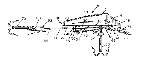
Fig. 1 is a side elevational view of a fishing device in
the form of a fishing plug mounted to a fish bait harness ac-
cording to this invention,
Fig. 2 is a bottom view of the device in Fig. 1 showing
a fish bait in phantom secured to the harness,
Fig. 3 is a top view of the device in Fig. 1,
Fig. 4 is a fragmentary side elevational view of this
invention illustrating the open position of the jaws forming
a part of the bait harness, and
-4-
13~510~
Fi~. 5 is a fra~mentary bottom vie~ of this invention
to illustrate the mo~able position of the bait impalin~ bar
and shohing a fish bait to be impaled.
Description of the Preferred Embodiments
Referring to the drawings, this ne~ fishing device
designated by the numeral 10 includes a buoyant artificial
plug type lure 12 of any desired configuration such as body 13
and, while not required, preferably is pro~ided with a con-
cave nose 14 at its leading end 16. Lure 12 may be in any
form common to such de~ices normally capable of use independ-
ently as bait but in accordance with the present in~ention is
mounted to a ja~s type fish bait harness 18. By this arrange-
ment, device 10 varies materiall~ from prior harness de~rices
identified earlier which, though sometimes identified as a lure,
are in fact only a bait harness attached to a fishing line and
do not include the feature of an independent lure in combination
with a harness as a part of the overall de-~ice. Plug 12 is
provided with a smooth or flat bottom 20, although this is not
required, to which harness 18 is secured as follows.
A rigid plate 22 of any suitable material and conforming
generally to the configuration of plug bottom 20 is preferably
secured thereto by an~ suitable means for which I have preferably
used a commelcially available adhesive (not shown). Preferabl~,
though not required for this invention, plate 22 at plug end 16
extends first downwardly as at 24 and then forhardly to form
a lip 26 which is a well known feature on many artificial
lures for directing them under water and for which no invention
--5-
131~
is claimed. Lip 26 is provided with an arcuate outer end 28.
Harness 18 includes an elongated fixed upper jaw 30
secured in longitudinal alignment with plate 22 by any suit-
able means such as rivets 32 and an opposed elongated movable
lower jaw 34. The openable ends of jaws 30, 34 are oriented
towards the trailing end 36 of plug 12 as at 38 (Fig.l) and
at their opposite ends, jaws 30, 34 are provided with nesting
ears 40, 42 which are pivotally connected by a spring loaded
pin 44 to normally hold said jaws in closed position and whereby
the lower jaw 34 at end 38 can be moved a~a~ fro~ jaw 30 by
pressure on the lip or lever 46 extending from ear 42 on jaw
34.
Spaced depending fixed sharp pointed prongs 48 (Figs.1,2,5)
are preferably mounted to plate 22 near end 38 of the upper
jaw 30 but can also be made integral with such jaw end if desired
and on end 38 of the lower jaw 34, there are spaced upstanding
sharp pointed pTongs 50 secured by a suitable fastening means 52
as best seen in Fig. 4. In this arrangement, prongs 48, 50
oYerlap each other in closed position as seen in Fig. 1 for
securely holding the fish bait 54 as will later appear.
A pin 56 is secured to and depends from plate 22 through
jaws 30, 34 adjacent jaw ears 40, 42 (Fig.l) and is pro~ided
with an eye 57 ~elow jaw 34 to carry any selected form of a
fish hook 58. An elongated flexible bar or rod 60 has a fTee
end 62, preferably sharpened as at 64, pTovided with a hole 66
and at its opposite end is pivotally attached to pin 56 inter-
mediate jaws 30, 34 (Figs.1,4). In the closed position of jaws
-6-
13151~5
30, 34 (Fig.l), bar 60 is disposed in longitudinal alignment
with plug 12 and extends intermediate prongs 48, 50 which serve
to hold bar 60 against lateral displacement from such alignment.
In the open position of jaws 20, 34, bar 60 is swingable on its
pivot connection to pin 56 to a position perpendicular to plug
12 as best seen in Fig. 5 where it is free and clear for hand-
ling to facilitate its being impaled or skewered through a fish
bait 54 from the mouth thereof to exit at the tail (Fig.2). Wi~h
the impaled or skewered bait, bar 60 is returned to longitudinal
alignment and in juxtaposition with plug 12 and when the jaws
30, 34 are closed, prongs 48, 50 will penetrate the bait 54 to
secure it to plug 12 for casting and trolling and hold it against
being pulled loose by the predator fish, water friction or snags.
Bar 60 is bendable to adjust the position of bait 54 and par-
ticularly to incline the tail downwardly causing the lure todig deeper with more side to side action. On bar end 62 pro-
truding from the tail of the bait 54, a suitable clip 68 carry-
ing another fish hook 70 is removably attached to bar end 62
- - - .. . . . .
through hole 66. It will be understood that the size and length
of lure 10 may be varied without change in its construction ac-
cording to the size of the predator fish and that additional fish
hooks may be imposed intermediate hooks 58, 70 if deemed desirable.
An eye hook 72 on portion 24 of lip 26 is provided to receive a
fishing line (not shown). The buoyancy of plug 12 serves to
support and maintain the fish bait 54 in a position resulting
in a natural side to side action thereof.
131~10~
hhen im~aling bar 60 through the fish bait 54, it is
recornmended that bait 54 be on its side (Fi~.5) relative to
lon~itudinal alignment with bar 60 so that ~hen such bar ~ith
the impaled bait is returned to longitudinal alignment ~ith
plug 12, the side of bait 54 will be flush against the bottom
20 of the plug 12 and securely held in this position when jaw
34 is closed. hith this arrangement, bait 5~ offers less resist-
ance in the ~ater and increases the side to side action hhich is
desired. The effectiveness of securing the cide of bait ~4 to
plug 12 hill be enhanced if bottom 20 is smooth or flat as
suggested earlier and l preferably use a plug 12 in such form.
~he results of using this device in this manner have been most
satisfactor) and appear to be an ad-~antage o~er fish bait harnesses
presently in use which generally secure the fish bate in an up-
right position. It will be understood, however, that while
securing the side of the fish bait to a flat bottomed plug has
produced satisfactory results, this is not required for the effect-
ive use of this invention. Accordingly, in view of the foregoing,
it is thought a full understanding of the construction and opera-
tion of this invention will be had and the advantages of the samewill be appreciated.
-8