Note: Descriptions are shown in the official language in which they were submitted.
A T~G ATTACHMENT SYSTEM
This invention concerns a tag attachment system
for the attachment of tags to the necks of bottles and
like necked articles by mechanical means.
According to this invention in one aspect there
is provided a tag attachment system comprising a carrier
strip having adhesive on one surface thereof and a
plurality of tags releasably secured at spaced intervals
lengthwise of the strip by said adhesive, each tag
having an aperture adjacent one end thereof for
engagement about the neck of a necked article, the face
of the tag facing said one surface having thereon a
coating of release material, and the areas of the strip
not covered by the tags being non-adhesive.
According to a preferred feature of the
invention, the end of each tag remote from said one end
has mean~ whereby said remote end can be adhesively
secured to the article. Preferably said means
comprises a portion at said remote end a surface of
which portion facing the strip carries an adhesive
operative to secure said portion releasably to the
strip.
The tag may have a folded leaflet attached
thereto. The leaflet may be held closed against the
tag by a cover sheet detachably secured to the tag at
25 opposite ends of the folded leaflet.
The invention also provides a method of
attaching tags to the necks of respective necked
containers moving in succession along a flow path with
the necks of the containers projecting at right angles
30 to the flow path, comprising feeding a carrier strip, in
the same general direction as the movement of the
containers, along a path which is inclined towards the
tops of the necks of the containers and which at a
location adjoining the flow path of said tops extends
35 about a guide from where the strip moves in a direction
generally opposite to the direction of movement of the
~k
13~5~
containers, which strip has adhesive on its surface
remote from the guide and a plurality of said tags
releasably secured at spaced intervals lengthwise of the
strip by said adhesive, each tag having a hole therein
adjacent its leading end with respect to the movement of
the strip for engagement over the neck of a container,
the face of each tag facing said surface of the strip
having thereon a coating of a release material, and the
areas of the strip not covered by the tags being non-
adhesive, whereby the leading end of each tag as it
comes to the guide peels from the strip so that the hole
is in the path of movement of and becomes engaged about
the top of the neck of one of the containers and the tag
becomes attached to the container.
The invention will now be described in more
detail with reference by way of example to the
accompanying diagrammatic drawings in which:
Figure 1 is a plan view of a tag application
~ystem according to the invention,
Figure 2 is a sectional view on the line 2-2 of Figure
1 ,
Figure 3 is a fragmentary view similar to Figure 1 of a
tag incorporating an additional feature,
Figure 4 is a view in the direction of the
arrow 4 of Figure 3,
Figure 5 illustrates a method according to the
invention of employing the tag application system, and
Figure 6 illustrates a modification of the
Figure 5 method.
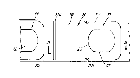
3 Referring to Figures 1 and 2 the system
employs a common strip to form a succession of tags 11
each formed with an aperture 12 near its leading end by
which the tags are to be looped over the necks of
bottles flowing along a conveyor line.
3 The carrier strip 10 is coated with a layer 14
of pressure-sensitive adhesive by which the tags 11 are
i315~6
-- 3 --
secured to the strip. Each tag has a coating 15 of a
silicone or other release material on its face secured
to the carrier strip.
A leaflet 16 attachment is adhesively bonded to
the upper face of the tag and overlies the whole area of
the tag except for a narrow strip 11a at the trailing
end of the tag. The leaflet is in this instance formed
from a strip of paper material the leading part 17 of
which is a single layer and overlies the corresponding
part of the tag and the trailing part 18 of which is
folded inward. The leading part 17 of the leaflet has
an aperture in register with the aperture 12 in the tag
and is secured to the tag by three spaced parallel
transversely extending lines of adhesive spaced apart
lengthwise of the tag. Thus there is a double
thickness of paper about the neck of the bottle for
strength while at the same time, the use of the
transverse parallel lines of adhesive improves the
flexibility of the leading part for reeling of the
strip~ The trailing part 18 of the leaflet comprises a
top part 19 which is a continuation of the leading part
17, a first continuation part 20 underlying the top part
19 and connected to the top part along a fold line 21,
and a second continuation part 22 which is connected
along a fold line 23 to the first continuation part and
which lies between the top and first continuation parts.
A transverse line of adhesive 24 along the trailing edge
of the first continuation part 20 secures the trailing
end of the leaflet to the tag. A line of perforations
3 25 is provided between the leading and trailing halves
and when torn open gives access to the inner parts of
the leaflet. These inner parts may or may not be
separable from the outer parts, whichever is desired.
Initially the whole upper surface of the carrier
strip is coated with adhesive 14 but the adhesive in the
areas not covered by the tags is subsequently rendered
" ~:
131~
-- 4 -
inactive by a varnish applied to these areas and exposure
to ultra-violet light in the known manner, so that the
strip carrying the tags can be formed into a roll.
Preferably a narrow band extending under the periphery
of the tag is similarly treated to render its adhesive
inactive.
A notch 26 is formed in the top sheet 19 at each
end of the line of perforations 25 and straddles the
line so as to show the position of the line.
In use, referring now to Figure 5, the strip is
fed, with the apertured ends of the tags leading, along
a downwardly inclined path towards the tops of a
succession of bottles 30 standing on a conveyor and
moving in the same general direction as the strip. At
the lower end of the path is a roller 31 of small
diameter about which the strip is led, the tags being on
the face of the strip remote from the roller.
At the downstream side of the guide roller the
strip is engaged in a clutch and brake mechanism 28
which feeds the strip forward stepwise one tag at a time
in response to a signal from a sensor 29 actuated by the
passing of a container on the conveyor. When the
clutch is thus operated the strip beneath a tag
commences to move about the roller, and the relative
stiffness of the tag and the release material on its
lower surface cause the tag 11 to commence to part from
the strip 10, and a bottle 30 on the conveyor is
arranged to pass under the roller 30 at the same time so
that its neck engages in the aperture in the tag and the
3 tag with its leaflet is transferred to the neck of the
bottle. The strip less the tags is fed to a take-up
spool (not shown) for discarding.
In a development illustrated in Figures 3 and 4
means is provided whereby the trailing end of the tag
can be adhesively secured to the bottle. A piece of
paper material 33 carrying a pressure-sensitive adhesive
131~
-- 5 --
34 is placed partly overlapping and secured to the
trailing end 1la of the tag, and the portion not
attached to the tag is releasably bonded to a
deactivated area of the strip, the varnish operating as
a release material when the tag is detached from the
strip so that the adhesive surface on the piece of paper
material can be used to secure the trailing end of the
tag to the bottle.
Referring now to Figure 6 a modified form of the
apparatus and method is illustrated. In this
apparatus, a vacuum box 35 is disposed above the guide
roller 31 and has an apertured bottom plate 36 which is
inclined downward towards the tops of the containers.
When the previous tag has become attached to its
container, the mechanism 28 actuates a forward step of
the strip, and as the strip is drawn about the roller
31, the leading tag peels off and becomes attached to
the underside of the plate by vacuum applied to the
vacuum box at an instant such that the apertured leading
end of the tag projects beyond the plate and comes to
rest in the path of the top of a container. The neck
of the container thus engages in the aperture and the
tag becomes engaged on the container. The container
may drop the tag from the plate, overcoming the vacuum,
or air may be blown into the vacuum box to discharge the
tag from the plate, as desired.
Holes in the vacuum plate may be blocked off to
give the exact pattern required.
It will be understood that the leaflet may
3 incorporate as many sheets as desired, may be in any
desired form and may be detachably or non-detachably
secured to the tag and with or without detachable parts,
and that the leaflet is omitted entirely.