Language selection

Search

Patent 1315558 Summary

Third-party information liability

Some of the information on this Web page has been provided by external sources. The Government of Canada is not responsible for the accuracy, reliability or currency of the information supplied by external sources. Users wishing to rely upon this information should consult directly with the source of the information. Content provided by external sources is not subject to official languages, privacy and accessibility requirements.

Claims and Abstract availability

Any discrepancies in the text and image of the Claims and Abstract are due to differing posting times. Text of the Claims and Abstract are posted:

  • At the time the application is open to public inspection;
  • At the time of issue of the patent (grant).
(12) Patent: (11) CA 1315558
(21) Application Number: 1315558
(54) English Title: CORRUGATED PLATE HEAT EXCHANGER
(54) French Title: ECHANGEUR DE CHALEUR EN TOLE FORTE ONDULEE
Status: Expired and beyond the Period of Reversal
Bibliographic Data
(51) International Patent Classification (IPC):
  • F28F 03/08 (2006.01)
  • F28F 19/00 (2006.01)
(72) Inventors :
  • GOLDSTEIN, VLADIMIR L. (Canada)
(73) Owners :
  • SUNWELL ENGINEERING COMPANY LIMITED
(71) Applicants :
  • SUNWELL ENGINEERING COMPANY LIMITED (Canada)
(74) Agent: MCCARTHY TETRAULT LLP
(74) Associate agent:
(45) Issued: 1993-04-06
(22) Filed Date: 1987-08-11
Availability of licence: N/A
Dedicated to the Public: N/A
(25) Language of filing: English

Patent Cooperation Treaty (PCT): No

(30) Application Priority Data:
Application No. Country/Territory Date
897,806 (United States of America) 1986-08-19

Abstracts

English Abstract


ABSTRACT OF THE DISCLOSURE
An ice-making machine includes a plurality of heat
exchangers disposed inside a housing and each having an inlet and
an outlet to permit circulation of coolant therethrough. Each of
the heat exchangers includes a pair of oppositely directed,
corrugated heat exchange surfaces to transfer heat from the fluid
within the housing to the coolant. Ice-making regions are
disposed between the heat exchangers. These regions each have an
inlet and an outlet to enable fluid to circulate therethrough.
Blade assemblies are provided in each of the ice-making regions
to co-operate with the heat exchangers to inhibit deposition of
ice on the heat exchangers. These blade assemblies each include
at least one blade of complementary shape to the corrugated heat
exchange surfaces to contact respective ones of the surfaces.
The blade assemblies are rotatable about an axis generally
perpendicular to the plane containing the surfaces. Drive means
rotate the blade assemblies at a rate such that the interval
between successive passes of the blades is insufficient to permit
crystallization of ice on the surfaces.


Claims

Note: Claims are shown in the official language in which they were submitted.


We claim:
1. An ice-making machine comprising a housing, a plurality
of heat exchangers disposed in said housing and each having an
inlet and an outlet to permit circulation of coolant
therethrough, each of said heat exchangers including a pair of
oppositely directed heat exchange surfaces at least one of which
is corrugated to transfer heat from fluid within said housing to
said coolant, ice-making regions disposed between said heat
exchangers each having an inlet and an outlet to enable fluid to
circulate therethrough, blade assemblies located in each of said
ice-making regions to co-operate with said heat exchangers to
inhibit deposition of ice on said heat exchangers, said blade
assemblies each including at least one blade of a complementary
shape to said heat exchange surfaces to contact respective ones
of said surfaces, each of said blade assemblies being rotatable
about an axis generally perpendicular to a plane containing said
surfaces, and drive means to rotate said blade assemblies at a
rate such that the interval between successive passes of said
blade assemblies is insufficient to permit crystallization of ice
on said surfaces.
2. An ice-making machine according to claim 1 wherein one
surface of one of said heat exchangers is directed toward one
surface of another of said heat exchangers and each of said blade
assemblies includes two pairs of blades supported on a common
carrier and rotatable in unison, one pair of blades being
directed toward one of said heat exchangers and the other pair of
blades being directed toward the other of said heat exchangers.
3. An ice-making machine according to claim 2 wherein each
of said blades are moveable about an axis parallel to said heat
exchange surface into engagement with said surface.
4. An ice-making machine according to claim 3 wherein said
common carrier is an arm supported by a rotatable shaft extending
through said housing.

5. An ice-making machine according to claim 4 wherein said
blades are inclined to the plane of the heat exchange surfaces.
6. An ice-making machine according to claim 5 wherein said
blades are pivotally mounted on said arm.
7. An ice-making machine according to claim 5 wherein each
of said blades is biased towards said heat exchange surfaces by
biasing means.
8. An ice-making machine according to claim 7 wherein each
pair of blades comprises a blade extending across the entire
length of said arm.
9. An ice-making machine according to claim 7 wherein each
pair of blades comprises a plurality of blade segments, each
segment extending across only a portion of the length of said arm
and being pivotally connected to said arm, said segments
extending across the entire length of said arm.
10. An ice-making machine according to claim 9 wherein said
blade segments comprise a plurality of flat plate strips formed
to correspond to the shape of said heat exchange surface, each
strip being connected at one edge to said arm by a coil spring
such that said edge contacts said heat exchange surface.
11. An ice-making machine according to claim 1 wherein said
blade is a flat plate having edges corresponding in shape to the
shape of said heat exchange surfaces and lip portions depending
from said edges, said blade extending between opposed heat
exchange surfaces in said ice-making region at an angle.
12. An ice-making machine according to claim 11 wherein
said blade is connected to an end portion of reduced width which
is mounted on a rotatable shaft extending through said housing,
said end portion extending at an angle to said blade and imposing
a torsional force on said blade to bias said blade towards said
heat exchange surfaces.

13. An ice-making machine according to claim 2 wherein said common
carrier comprises a sleeve mounted on a rotatable shaft, said sleeve having friction
means associated therewith to allow for rotation thereof with the shaft and to allow
for decoupling of said shaft and said sleeve for relative rotation therebetween when
said sleeve is inhibited from rotating with said shaft.
14. An ice-making machine according to claim 13 wherein said friction
means comprises a shear pin connecting said sleeve to said shaft.
15. An ice-making machine according to claim 13 wherein said friction
means comprises a friction coupling.
16. An ice-making machine according to claim 13 wherein said friction
means comprises a pair of brake pads, one of said pads being keyed to said sleeve
and the other of said pads being keyed to said shaft.
17. An ice-making machine according to claim 2 further including a
scraper assembly rotatable with said common carrier to scrape excess ice deposited
on said heat exchange surfaces.
18. An ice-making machine according to claim 17 wherein said scraper
assembly is complementary in shape to said heat exchange surface and is spaced
therefrom.
19. A blade assembly suitable for scraping a corrugated heat transfer
surface of a heat exchanger, said blade assembly including at least one blade of a
complementary shape to the corrugated heat exchange surface to contact said
surface, and biasing means to bias said blade towards said surface to maintain
contact therebetween, said blade assembly being rotatable about an axis generally
perpendicular to a plane containing said heat transfer surface.
11

20. A blade assembly according to claim 19 wherein said blade assembly
includes two pairs of blades supported on a common carrier and rotatable in
unison.
21. A blade assembly according to claim 20 wherein each of said blades
are moveable about an axis parallel to said heat exchange surface into engagement
with said surface.
22. A blade assembly according to claim 21 wherein said common
carrier is an arm supported by a rotatable shaft extending through said housing.
23. A blade assembly according to claim 22 wherein said blades are
inclined to the plane of the heat exchange surfaces.
24. A blade assembly according to claim 23 wherein said blades are
pivotally mounted on said arm.
25. A blade assembly according to claim 24 further including a pair of
arms wherein each of said arms has a blade extending across the entire length
thereof.
26. A blade assembly according to claim 24 further including a pair of
arms wherein each of said arms comprises a plurality of blade segments, each
segment extending across only a portion of the length of said arm and being
pivotally connected to said arm, said segments extending across the entire length
of said arm.
27. A blade assembly according to claim 26 wherein said blade segments
comprise a plurality of flat plate strips formed to correspond to the shape of said
heat exchange surface, each strip being connected at one end to said arm by a coil
spring such that said edge contacts said heat exchange surface.
12

28. A blade assembly according to claim 19 wherein said at least one
blade is a flat plate having edges corresponding in shape to the shape of said heat
exchange surfaces and lip portions depending from said edges, said at least one
blade extending between opposed heat exchange surfaces in said ice-making regionat an angle.
29. A blade assembly according to claim 28 wherein said at least one
blade is connected to an end portion of reduced width which is mounted on a
rotatable shaft extending through said housing, said end portion extending at anangle to said at least one blade and imposing a torsional force on said blade to bias
said at least one blade towards said heat exchange surfaces.
30. A blade assembly according to claim 20 wherein said common
carrier comprises a sleeve mounted on a rotatable shaft, said sleeve having friction
means associated therewith to allow for rotation thereof with the shaft and to allow
for decoupling of said shaft and said sleeve for relative rotation therebetween when
said sleeve is inhibited from rotating with said shaft.
31. A blade assembly according to claim 30 wherein said friction means
comprises a shear pin connecting said sleeve to said shaft.
32. A blade assembly according to claim 30 wherein said friction means
comprises a friction coupling.
33. A blade assembly according to claim 30 wherein said friction means
comprises a pair of brake pads, one of said pads being keyed to said sleeve and the
other of said pads being keyed to said shaft.
34. A blade assembly according to claim 20 further including scraper
elements rotatable with said common carrier to scrape excess ice deposited on said
heat exchange surfaces.
13

35. A blade assembly according to claim 34 wherein said scraper
elements are complementary in shape to said heat exchange surface and are spacedtherefrom.
14

Description

Note: Descriptions are shown in the official language in which they were submitted.


131~5~
This invention relates to ice-making machines
and more particularly to a corrugated plate heat
exchanger for use in an ice-making machine.
Canadian patent application number 485,911
filed on June 29, 1985 discloses a heat exchanger
suitable for making ice. ~his heat exchanger consists
of a housing having a fluid inlet and outlet. Disposed
in this housing are a plurality of heat exchangers, each
having an inlet and an outlet to permit circulation of
coolant therethrough. Each heat exchanger has a pair of
oppositely directed heat exchange surfaces to allow heat
exchange between the fluid within the housing and the
coolant. A blade assembly is mounted on a rotatable
shaft extending through the centre of the housing. The
blade assembly consists of a disk with a plurality of
blades attached on either side thereof by hinges. The
blades on one side are directed towards the surface of
ons heat exchanger, and the blades on the other side are
directed towards the surface of another heat exchanger.
These blades scrape the surface of the heat exchangers
to inhibit crystallization of ice thereon.
It ~s an object of the present invention to
improve the efficiency of the heat exchangers described
above.
Accordingly, the invention provides an ice-
maklng machine which includes a plurality of heat
exchangers disposed inside a housing, each having an
inlet and an outlet to permit circulation of coolant
~herethrough. Each of the heat exchangers includes a
pair of oppositely directed, heat exchange surfaces at
least one of which is corrugated to transfer heat from
the fluid within the housing to the coolant. Ice-making
A ~

1 3 ~
regions are disposed between the heat exchangers. These
regions each have an inlet and an outlet to enable fluid
to circulate therethrough. Blade assemblies are
provided in each of the ice-making regions to co-operate
with the heat exchangers to inhibit deposition of ice on
the heat exchangers. These blade assemblies each
include at least one blade of complementary shape to the
corrugated heat exchange surfaces to contact respective
ones of the surfaces. The blade assemblies are
rotatable about an axis generally perpendicular to the
plane containing the surfaces. Drive means rotate the
blade assemblies at a rate such that the interval
between successive passes of the blades is insufficient
to permit crystallization of ice on the surfaces.
Preferably, biasing means are provided to bias
the blade assemblles towardq the surfaces to maintain
contact therebetween.
The use of a corrugated heat exchanger in the
present invention provides the advantage of increased
heat transfer area and improved rigidity for the
surface. The corrugated heat exchange surface does not
tend to warp as easily as a flat heat exchange surface,
thus wear on the blades is reduced. The complementary-
shaped blades are used to scrape the heat transfer
surfaces to ensure that no ice crystallizes on the
surface of the heat exchanger.
An embodiment of the present invention will
now be described, by way of illustration only, with
reference to the following drawings in which:
Figure 1 is a front view of a heat exchanger
ln partial cross-~ection;

1 3 ~
- 2a -
Figure 2 is a side view of the heat exchanger
of Flgure l;
Figure 3 is a cross-sectional view of a
portion of the heat exchanger of Figure 1;
Figure 4 is a view in the direction of the
arrow A in Figure 3;
Figure 5A is a front view of a blade assembly
to be used in the heat exchanger of Figure 2;
Figure 5B is a front view of an alternative
embodiment of a blade assembly to be used in the heat
exchanger of Figure 1;
Figure 5C is a front view of another
alternative embodiment of a blade assembly to be used in
the heat exchanger of Figure 1;
Figure 5D is a perspective view of the blade
assembly of Figure 5C;
A
~a

131~8
Figure 5E is a front view of still another alternative
embodiment of a blade assembly;
Figure 5F is a cross-sectional view along line F-F of
Figure 5E;
Figure 5G is a front vi.ew of the blade of Figure 5E
attached to a shaft;
Figure 6 is a cross-sectional view of a portion of an
alternative embodiment of a heat exchanger similar to that shown
in Figure 1;
Figure 7 is a view in the direction of arrow B of
Figure 6; and
Figure 8 is a side view in partial cross-section of an
alternative embodiment of the embodiment of Figure 6.
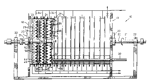
Referring to Figures 1 and 2, it can be seen that the
ice~making machine 10 includes a housing 12 having a top wall 14,
side walls 16 and end walls 18. The end walls 18 are square when
viewed in plan and co-operate with the top wall 14, bottom walls
15 and side walls 16 to define an enclosure.
A hollow agitator shaft 20 with open ends 21 each of
which are rotatably connectable to a respective brine inlet pipe
23, extends through the housing between the end walls 18. This
shaft is rotatably supported at opposite ends by bearings 22
located outside of the housing and is rotatable by a motor.
As can best be seen in Figures 1 and 3, a plurality of
heat exchangers 24 are located at spaced intervals within the
housing 12. Each heat exchanger 24 consists of a pair of
circular plates 25 with apertures 28 therein to accommodate the
shaft 20, spaced apart by inner and outer gaskets ~9, 30. A
spiral ring or honeycomb structure (not shown) may be disposed
between each pair of plates 25 and bonded thereto by appropriate
m0ans to provide increased structural rigidity. These plates 25
have corrugations 27 which extend in the circumferential
direction as can best be seen in Figure 4 to provide corrugated

1 3 ~
heat exchange surfaces 26. The plates 25 are each supported near
their bottom ends 32 by a pair of supports 33 extending inside
the housing 12 along the length of the housing 12. Each heat
exchanger 24 has an inlet 34 on the top end 31 thereof and an
outlet 36 at the bottom end 32 thereof. Alternatively the inlet
could be at the bottom end 32 and the outlet could be at the top
end 31.
Disposed between each pair of heat exchangers 24 are
ice-making regions 38. Outlets 42 are located at the bottom end
44 of each region. A blade assembly 46 is situated in each
ice-making region 38. Each blade assembly 46 includes a pair of
arms 48 mounted generally perpendicular to the shaft 20 on a
collar 50 fixed to the shaft 20. These arms 48 communicate with
the shaft 20 through openings 54 in the shaft
20. The arms 48 are tubular and have a plurality of spaced
openlngs 56 along the length thereof. Two blades 58 extending
along substantially the entire length of the arms are pivotally
connected to each of the arms 48 by hinges 59. As can be seen in
Figures 3 and 5a, each blade 58 consists of a plate having a
generally straight edge 61 which is hinged to an arm, and a
notched edge 63 shaped to conform to the shape of the surface 26
of the heat exchanger. One blade 58 is hinged to the side of the
arms 48 disposed towards the heat exchanger surface 26 of one
heat exchanger, and another blade 58 is attached to the side of
the arms disposed towards the heat exchange surface of an
ad~acent heat exchanger. Torsion springs 62 are connected to the
blades 58 and arms 48 to bias the blades 58 in scraping relation
with a respective heat exchange surface 26.
In an alternative embod$ment, brine inlets would be
located in the bottom of each ice making region and brine outlets
would be at the top of each region.
In operation, brine is fed into both ends 21 of the
agitator shaft 20. The brine passes through the openings 54 in
,

13 ~ 8
-- 5
the shaft 20 into the arms 48, and enters the ice-making regions
through openings 56 in the arms 48. Refrigerant enters each of
the heat exchangers 24 through the inlets 34 and exits through
the outlets 36. As the refrigerant passes through the heat
exchangers 24 it absorbs heat through the heat exchange surfaces
26 and boils. The brine in contact with the heat exchange
surfaces 26 is thus supercooled. To avoid deposition of ice on
the surfaces 26 which would inhibit heat transfer~ the blade
assemblies are rotated by the shaft 20. Rotation of the shaft 20
rotates the arms 48 and thereby sweeps the blades 58 over
respective heat exchange surfaces 26. Movement of the blades
removes the supercooled brine from adjacent the surfaces 26 and
distributes it through the body of the brine solution. The
supercooled brine will crystallize on centres of crystallization
present in the solution and in turn acts as new centres for
crystallization to generate 3-dimensional crystalllzation of the
water within the brine solution and thus promotes the formation
of ice in a crystalline manner. The brine solution with the
crystallized ice in suspension is extracted from the outlets 42.
Figures 5B to F show three alternative embodiments of
the blade shown in Figure 5A. In Figure 5B, instead of using a
single blade, several triangular blade segments 64 corresponding
in shape to the corrugated heat exchange surfaces 26 are each
pivotally connected to an arm 48 by a respective hinge 66. A
torsion spring 68 is associated with each segment 64 to bias the
segments 64 towards a heat exchange surface 26a.
Figure 5C and D show another alternative embodiment of
the blades. In this embodiment there are several blade segments
67 which are each made up of a flat plastic strip 68 bent into a
"V" shaped formation corresponding in shape to the shape of the
heat exchange surfaces 26. A plate 70 extends between and is
attached to opposite sides 72, 74, of each "Vl' shaped strip. A
coil spring 80 is attached to each plate 70 at one end and to an
arm 48 at the other end. The springs 80 bias each strip 68

131~
towards the heat exchange surface 26 such that each strip 68 is
disposed at an angle to the surface with only the edge of the
strip 68 ln contact with the heat exchange surface 26, as can be
seen in Figure 5D.
Figures 5E, F and G show another embodiment wherein the
blade 75 is wider than the ice-making region, and has corrugated
edges 76 with corrugated lip portions 78 depending from the edges
76. These edges 76 correspond in shape to the shape of the heat
exchange surfaces 26 defining the ice-making regions. The blade
assembly has an end portion 80 of reduced thickness (Figure 5G)
extending from the blade which is attached to the shaft 20,
rather than to an arm 48. The blade is twisted at an angle to
the end portion 80 to fit between the heat exchange surfaces
defining the ice-making region, so that the edges 76 and the lip
portions 78 contact respective opposed heat exchange surfaces
26. The end portion 80 exerts a torsional force on the blade 75
to bias the blade 75 against the heat exchange surfaces 26.
Alternatively, the end portion 80 could be of the same thickness
and could be pivoted to the shaft 20 and biased at an angle.
Figures 6 and 7 show an alternative embodiment of the
invention. Elements of this embodiment corresponding to elements
in the embodiment illustrated in Figures 1-4 have been given the
same reference numerals followed by the letter "H". This
embodiment has been designed to reduce freeze-up and alleviate
some of the problems whic~ may occur if freeze-up of any of the
individual ice-making regions occurs. Normally when freeze-up
occurs, damage to the equipment will result since the blade in
the ~rozen region will be inhibited from rotating with the shaft.
As can be seen in these Figures, this embodiment is
similar to the embodiment of Figures 1-4 except that the sleeve
52H is connected to the shaft 20H by a breakable shear pin 82.
In addition to blade assemblies 46H, a pair of diametrically
opposed scrapers 86 are located on the sleeve 52H. These

1 3 ~ 8
-- 7 --
scrapers are of generally the same shape as the blade assemblies
46H, however, their edges 88 are spaced from the heat exchange
surfaces.
In operation, if freeze-up occurs, the scrapers 86 will
scrape away any excess buildup of ice on the heat exchanger
surfaces 26H. If too much ice builds up and the scrapers cannot
remove it, the shear pin will break and allow rotation of the
shaft relative to the sleeve 52H.
An alternative embodiment to alleviate the problems
encountered during freeze up is shown in Figure 8. Elements
similar to those previously described are given the same
reference numeral, followed by the letter "J". In this
embodiment, a slip arrangement comprises a first brake pad 86
keyed to the sleeve 52J by interlocking splines 88 and a second
brake pad 90 keyed to the shaft 20J by interlocking splines 92.
A ring 94 is attached to the shaft ad~acent to the brake pad 92
and a spring 96 is disposed between this ring 94 and the brake
pad 92 to bias the second brake 92 pad into contact with the
first pad 90.
During normal operation, the frictional force between
the brake pads will provide for common rotation of the sleeve 52J
and shaft 20J. Upon freeze up, rotation of the sleeve 52J will
be inhibited and the frictional force between the brake pads 90,
92 will be overcome to allow for relative rotation between the
sleeve 52J and shaft 20J. The brake pads may be enclosed in a
housing (not shown) if desired to avoid any interference from the
ice-making environment. This slip arrangement can be replaced by
a shear pin, a friction coupling or any device that would be
apparent to one skilled in the art that would provide for common
rotation of the sleeve 52~ and shaft 20H under normal
circumstances and provide for decoupling of the sleeve and shaft
when freeze-up occurs to an extent that the sleeve is inhibited
from rotating.

1 3 ~
- 8 -
It is to be appreciated that changes can be made to the
preferred embodiments of the invention within the scope of the
inven-tion as described and claimed. There can be any number of
heat exchangers 24 and ice-making regions 38. There could be one
inlet for the ice-making regions 38 and one outlet, with fluid
communication between ice-making regions. Also, the blades 58
could be carried by rotating disks instead of arms 48.

Representative Drawing
A single figure which represents the drawing illustrating the invention.
Administrative Status

2024-08-01:As part of the Next Generation Patents (NGP) transition, the Canadian Patents Database (CPD) now contains a more detailed Event History, which replicates the Event Log of our new back-office solution.

Please note that "Inactive:" events refers to events no longer in use in our new back-office solution.

For a clearer understanding of the status of the application/patent presented on this page, the site Disclaimer , as well as the definitions for Patent , Event History , Maintenance Fee  and Payment History  should be consulted.

Event History

Description Date
Inactive: IPC expired 2018-01-01
Time Limit for Reversal Expired 2006-04-06
Inactive: IPC from MCD 2006-03-11
Letter Sent 2005-04-06
Grant by Issuance 1993-04-06

Abandonment History

There is no abandonment history.

Fee History

Fee Type Anniversary Year Due Date Paid Date
MF (category 1, 5th anniv.) - small 1998-04-06 1998-02-03
MF (category 1, 6th anniv.) - small 1999-04-06 1999-04-06
MF (category 1, 7th anniv.) - small 2000-04-06 2000-03-09
MF (category 1, 8th anniv.) - small 2001-04-06 2001-02-23
MF (category 1, 9th anniv.) - small 2002-04-08 2002-04-05
MF (category 1, 10th anniv.) - small 2003-04-07 2003-04-04
MF (category 1, 11th anniv.) - small 2004-04-06 2004-04-06
Owners on Record

Note: Records showing the ownership history in alphabetical order.

Current Owners on Record
SUNWELL ENGINEERING COMPANY LIMITED
Past Owners on Record
VLADIMIR L. GOLDSTEIN
Past Owners that do not appear in the "Owners on Record" listing will appear in other documentation within the application.
Documents

To view selected files, please enter reCAPTCHA code :


To view images, click a link in the Document Description column. To download the documents, select one or more checkboxes in the first column and then click the "Download Selected in PDF format (Zip Archive)" or the "Download Selected as Single PDF" button.

List of published and non-published patent-specific documents on the CPD .

If you have any difficulty accessing content, you can call the Client Service Centre at 1-866-997-1936 or send them an e-mail at CIPO Client Service Centre.


Document
Description 
Date
(yyyy-mm-dd) 
Number of pages   Size of Image (KB) 
Claims 1993-11-21 6 191
Drawings 1993-11-21 7 216
Abstract 1993-11-21 1 26
Descriptions 1993-11-21 9 319
Representative drawing 2001-07-30 1 25
Maintenance Fee Notice 2005-05-31 1 172
Fees 2003-04-03 1 49
Fees 2002-04-04 1 53
Fees 2000-03-08 1 50
Fees 1998-02-02 1 56
Fees 2001-02-22 1 50
Fees 1999-04-05 1 51
Fees 2004-04-05 1 52
Fees 1997-03-31 1 56
Fees 1996-04-08 1 41
Fees 1995-04-09 1 40
Correspondence 1993-01-06 2 48