Note: Descriptions are shown in the official language in which they were submitted.
1 3 L~r~
TITLE
APPAR~TUS FOR ALIGNING GLASS 5HEETS
IN A PRODUCTION LINE
The present invention relates generally to an
5 apparatus for aligning glass shee~s in a production line
and, particularly, to an apparatus for aligning sheets in a
windshield bending operation.
- The movement of glass sheets along a production line
presents the problem of properly aligning the sheets at one
10 or more work stations. One prior art aligning apparatus is
disclosed in ~.S. Patent No. 3,638,564 in which a glass
sheet is moved on a conveyor belt to an orientating station
l, where a pair of edge engaging members and a pair of end
¦ ~ngaging members orient the glass sheet longitudinally and
¦ 15 laterally on the conveyor belt. Suction then is applied to
hold the glass sheet in place while the conveyor belt moves
the glass sheet to a work station where a predetermined
pattern is applied by a sil~screen process. Each of the
edgè engaging members is hydraulically actuated and its
20 relative position is manually adjustable by rotation of a
~, ~hreaded rod in a thxeaded sleeve to which a hydraulic
!I cylinder is pivotly secured.
¦ U.S. Patent No. 3,701,643 and U.S. Patent No.
3,992,182 both di~close aligning devices for positioning a
25 moving glass sheet on a conveyor in a glass sheet
production line. A pair of glass edge engagement members
are located on opposite sides of the conveyor and move with
the conveyor at the speed of the glass sheet. The
engagement members are mounted on reciprocating carriages
30 which move into and out of engagement with opposed edges of
the glass sheets to align them.
U.S. Paten~ No. 4,205,744 discloses a device for
locating a windshield as it is being moved between two
conveyor lines. A locating bar is manually adjustable on a
35 threaded shaft to permit location of various lengths of
~ 3~ 3~
windshields. A pair of locating pads are provided at the
ends of the locating bar. ~ windshield is moved by a first
conveyor into a holding structure which will rotate the
windshield through 180 and move it latPrally to place it
5 on the end of a second offset conveyor. During the lateral
movement, one edge of the windshield comes into contact
with one of the locating pads to position the windshield
when it is placed on the second conveyor.
U.S. Patent No. 4,367,107 discloses an apparatus for
10 aligning a pair of bent glass sheets in an assembly
station. The stacked glass sheets are moved into the
assembly station and guide roll~rs engage the top and
bottom edges and the end edges of the glass sheets. Both
sheets are engaged by suction means and separated
15 vertically while a flexible shee~ layer is inserted between
them. The glass sheets are reassembled to form a sandwich
to be laminated.
U.S. Patent No. 4,440,288 and U.S. Patent No.
4,~88,846 both disclose sensors for controlling the spacing
, 20 of objects being moved between two conveyors. In the '288
~ patent, pans of dough are collected at a gate positioned at
! the end of a grouping conveyor being fed from an unloader
conveyor. A pan sensor is moved along the grouping
conveyor to determine when a moving pan is a predetermined
I 25 distance from one or more stopped pans so that the speed of
the conveyor can be reduced below a speed at which rising
dough would fall when the moving pan strikes the stopped
pan. The '846 patent discloses a device for controlling
the movement of an auxiliary conveyor which is feeding
30 glass sheets onto a main conveyor. The auxiliary conveyor
is stopped until the distance between the last sheet on the
main conveyor and the next sheet on the auxiliary conveyor
is equal to a predetermined distance at which point the
auxiliary conveyor is started to move the stopped glass
35 sheet onto the main conveyor.
~31~'3~
U.S. Patent No. 4,493,412 discloses a device for
positioning glass sheets on a conveyor platform prior to
removal by a robot. A leading edge of the glass sheet
engages fixed stop pins. Then a pair o~ transversely
5 moveable tables advance to engage the opposed side edges of
the article. Finally, adjustable pins are moved vertically
and longitudinally into engagement with the trailing edge
of the article to align the article in a precise position
relative to a fixed reference point.
U.S. Patent No. 4,45~628 discloses a turn table for
supporting a glass panel and moving it relative to a robot
which applies an adhesive to an edge of the panel. The
glass panel is supplied to the turn table by a conveyor.
¦ The panel is located on the turn table by a plurality of
¦ 15 positioning shoes hydraulically actuated in a vertical
direction to engage the peripheral edges of the glass
panel. The panel is then gripped with vacuum cups and the
shoes are retracted before the turn table begins rotation.
- In a laminated anti-laceration windshield production
i 20 line~ an outer curved sheet, an inner curved sheet and a
curved cover plate are stacked with intervening plastic
1 layers. These glass sheets must be properly oriented prior
! to the lamination process in order to provide proper edge
alignment for accepting a vacuum ring. Since the glass
25 sheets are curved, they are formed of decreasing length
from the outer sheet to the inner cover plate such that the
; edges can be aligned. All of the prior art systems
; discussed above would have a problem properly aligning the
three differently sized sheets.
The present invention is an apparatus for aligning
different size glass sheets as they are conveyed in a
predetermined order to the entrance of a furnace. The
sheets are oriented transverse to the direction of travel.
The furnace heats the glass sheets to softening
35 temperatures suitable for bending. A pair of vertically
extending stops engage the leading edge of the glass sheet
~ ~ ~ 5 ~ ~ ~
in front of the opening to the furnace. A pair of side
pushers are actuated in a hori~ontal direction to move into
engagement with the opposed ends of the glass sheet to
align it into a predetermined position. The pushers and
5 the front stops are then removed and the con~eyor moves the
sheet through the furnace. The distance between the side
pushers is automatically adjusted by a stepper motor drive
to accommodate the different lengths of glass sheets.
The apparatus also includes a control system and
10 sensors for responding to the absence or misalignment of
the glass sheets. Sensors mounted at the sides of the
conveyor;adjacent the entrance ~o the furnace will detect
the absence of a sheet and sound an alarm indicating that
the orderly sequence of glass sheets has been interrupted.
15 Sensors in the bending area will detect whether the
assemblies entering the bending apparatus are skewed. If
the assemblies are skewed, the front stops will be
automatically adjusted to realign the glass sheets as they
enter the furnace. A sensor at the entrance to the furnace
20 can also he utilized to detect indicia on the glass sheets
to determine that they are in the proper order and/or to
determine if a sheet is missing. Sensors can also be
located at the front of the furnace to detect a skewing
problem and control the location of the front stops to
25 correct the problem before the glass sheets reach the
bending area.
Accordingly, it is an object of the present invention
to provide an aligning apparatus which facilitates the use
of a conventional vacuum ring on curved windshield
30 assemblies stacked for lamination.
It is another object of the present invention to
provide an apparatus for aligning glass sheets which
automatically adjusts to different size sheets as they are
moved down an assembly line.
~. 3 ~, ~ r~
In the accompanyiny drawings:
Fig. 1 is a top plan view o-E a portion of a windshield
bending installation including an alignment apparatus in
accordance with the present invention;
Fig. 2 is a perspective view of the alignment
apparatus shown in Fig. 1 with most of the actuating
mechanism removed for viewing purposes;
Fig. 3 is a top plan view of the forward stop
mechanism of the alignment apparatus shown in Figs. 1 and
10 2;
Fig. 4 is a top plan view of the side alignment
mechanism of the alignment apparatus shown in Figs. 1 and
2;
Fig. 5 is a cross-sectional view taken along the line
15 5-5 of Fig. 3;
Fig. 6 is a cross-sectional view taken along the line
6-6 in Fig. 3;
Fig. 7 is a cross-sectional view taken along the line
7-7 in Fig. 3;
Fig. 8 is a cross-sectional view taken along the line
8-8 in Fig. 5;
Fig. 9 is a cross-sectional view taken along the line
9-9 in Fig. 4; and
Fig. 10 is a cross-sectional view taken along the line
25 10-10 in Fig. 9.
Fig. 11 shows a control system for automatically adjusting
the stop tubes used with this invention,
According to the present invention, there is provided
an apparatus for aligning sheets of material of different
dimensions with respect to a reference point, characterized
by at least two stop pins positioned in a plane in which
30 sheets of material are to be aligned f~or engaging a leading
edge of sheet.s of material in said plane to align said
sheets with respect to a reference point; at least one side
aligning means positioned in said plane at a selected one
of at least two different predetermined dis~ances from said
35 reference point for engaging an end edge of sheets of
material in said plane to align said sheets with respect to
~3~ 13~
said reference point; means for automatically selecting one
of said predetermined distances in accordance with a
predetermined sequence of delivery of sheets of material of
different dimensions to said stop pins; and means for
5 moving said side aligning means relative to said reference
point in response to said means for automatically
selecting.
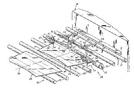
There is shown in Fig. 1 a portion of a windshield
bending installation including a first or supply conveyor
10 20 which delivers glass sheets to the entrance of a furnace
21 for heating the glass sheets to bending temperatures.
As the sheets leave the furnace 21, they enter a bending
station 22 where they are shaped to the desired curvature
by suitable bending apparatus 22a and transported by a
15 second conveyor 23 to a cooling station ~not shown~. ~s
shown in Fig. 1, a glass sheet 24 has been transported by
the supply conveyor 20 to the entrance to an alignment
apparatus 25 in accordance with the present invention.
Another glass sheet 26 has just left the alignment
~j 20 apparatus 25 and is about to enter the furnace 21. The
alignment apparatus 25 positions the glass sheets such that
they enter the ~ending station 22 in the proper orientation
and they exit the furnace 21 in the same orientation.
Accurate alignment of the individually sized sheets
25 relative to the the bending apparatus 22a is necessary so
that after shaping, the sheets of each set will nest
properly with their edges in alignment to insure a good fit
for the vacuum ring used in the laminating process.
As shown in Fig. 2, the conveyor 20 can include a
30 plurality of rollers 30 which are aligned in a horizontal
plane leading to an entrance opening 31 in the furnace 21.
The drive mechanism for the rollers is conventional and is
not shown. In Fig~ 2, the glass sheet 26 is shown in the
alignment apparatus 25 and the glass sheet 24 is shown as
35 the next sheet in a sequence of glass sheets which will be
explained below.
~3~73~
The alignment apparatus 25 includes a front or leading
edge positioning mechanism 32 and a side or end edge
positioning mechanism 33, both of which are shown without a
portion of the associated control mechanism in order to
5 better view the engagement with the edges of the glass
sheet 26. The glass sheets 24 and 26 are depicted as
elements of a laminated windshield. For example, the glass
sheet 26 can be an outer light having a lower edge 34, and
upper edge 35, and side or end edges 36 and 37. The glass
10 sheets are oriented such that the lower edge 34 is a
leading edge as the glass she~t is moved down the
production line~ It is desir~d to position the glass sheet
~ 26 such that the end edges 36 and 37 are equidistant from
¦ an imaginary center line 38 which extends through the
15 furnace 21 and the bending apparatus 22a to assure that
when the glass sheets are stacked for laminating, the edges
are properl~y aligned to accept a ~acuum ring. The glass
sheet 24 can be, for example, an inner light which is
stacked on top of the glass sheet 26 in an assembly station
i 20 (not shown) to form a sandwich with a plastic sheet in
between. If a laceration shield window assembly is being
j manufactured, a third glass sheet which is a removable
¦ cover plate is stacked on top of the glass sheet 24 with an
!l anti-lacerative sheet between them to complete the window
25 assembly.
As shown in FigO 2, the front or leading edge
positioning mechanism 32 includes a splined shaft 40
positioned parallel to the rollers 30 and above the path of
travel of the glass sheets 24 and 26 on the rollers 30.
30 The shaft 40 is rotatably supported, as will be described
below, and extends through a pair of bearing blocks 41
associated with a pair of front stop assemblies. Although
two front stop assemblies are shown, any suitable number of
front stop assemblies can be utilized. Each bearing block
35 41 is mounted on a top surface of a front stop slide
mounting bracket 42. Mounted on the lower surface of each
~ 3~L~irl3~
mounting bracket 42 is slide mechanism 43 actuated by an
electric motor ~4. Extending vertically downwardly from
the slide mechanism 43 is a stop tube 45. Typically, the
stop tubes 45 are positioned equidistant from the center
5 line 38 to engage the lower or leading edge 34 of the glass
sheet 26.
Attached to the shaft 40 between the bearing blocks 41
is one end of a spline rotating lever 46. The other end of
the lever 46 is attached to a piston rod e~tending from an
10 air cylinder 47. Although not shown in Fig. 2, the air
cylinder 47 is fixed with respect to the mounting of the
shaft 40. When the air cylinder 47 is actuated to retract
the rod, the lever arm 46 rotates the shaft 40 and the
attached stop mechanisms in a counterclockwise direction as
15 viewed from the end of the shaft 40 closest to the viewer~
The stop tubes 45 are moved away ~rom the lower or leading
edge 34 of the glass sheet 26 thereby allowing the glass
sheet 26 to proceed along the conveyor 20 into the entrance
opening 31 of the furnace 21.
d 20 The side or end edge positioning mechanism 33 includes
` a pair of oppositely threaded shafts 50 and 51 connected
i together by a coupling 52. The shafts 50 and 51 are
rotatably mounted in a support apparatus (not shown) which
will be described below. An electric stepping motor 53 is
25 attached to the free end of the shaft 50. Each of the
shafts 50 and 51 is threadably engaged in a bearing block
54. ~ach bearing block 54 is mounted on an upper side of a
side pusher mounting bracket 55. An air cylinder 56 is
mounted on the underside of the mounting bracket 55 and a
30 rod of the air cylinder 56 is attached to a side pusher
bracket 57 which extends generally parallel to the center
line 38. When the air cylinders 56 are actuated to retract
the rods, the brackets 57 are moved into engagement with
the side or end edges 36 and 37 of the glass sheet 26 to
35 position the glass sheet with respect to the center line
38. The stepper motor 53 can be actuated to rotate the
~ 3~ ~3~
threaded shafts 50 and 51 by a predetermined amount to
adjust the spacing between the brackets 57 for different
length sheets.
Referring to Figs. 3 and 5 through 8, the front or
5 leading edge positioning mechanism 32 is shown in more
detail. The glass sheet 26 is supported by a plurality of
the rollers 30. The lower or leading edge 34 of glass
_sheet 26 is moved toward the furnace until it engages the
lower ends of the stop tubes 45. At least the lower end of
10 each stop tube 45 is hollow and encloses a helical spring
60. The lower end of the spring 60 abuts an upper end of a
stop pin 61. The lower end of the stop pin 61 extends from
the lower end of the tube 45 into engagement with the edge
34. The stop pin 61 is typically formed of a material
15 which will not scratch the glass sheet 26 such as a nylon.
The spring 60 and the stop pin 61 can be retained in the
tube in any conventional manner which permits the pin to be
forced into the tube against the spring. Such operation
~prevents the breakage of glass sheets should the tube 45 be
,l,20 lowered in a manner such that the lower end of the stop pin
61 engages the upper surface of a sheet of glass rather
than the leading edge. The lower end of the stop tube 45
is positioned above the upper surface of the plane of the
glass sheet 26.
! ~5 The upper end of the stop tube 45 is attached to a
moveable slide 62 included in the slide mechanism 43O The
slide mechanism 43 is commercially available as a "Velmex
Unislide #S-B2593WlJ" from Velmex Inc., E. sloomfield,
N.Y., U.S.A. The attached electric motor 44 can be a
30 Bodine type "K" model #730 available from Bodine Electric
Co., Chicago, Ill., U.S.A. The slide mechanism 43 and
motor 44 can be utilized to selectively position the stop
pin 61 to determine the reference point at which glass
sheets will be stopped before entering the furnace.
~31~3~
As shown in Figs. 5 and 8, an upper end of the stop
tube 45 is threadably received on a drive shaft 63 which is
connected to the motor 44. When the motor 44 rotates the
drive shaft 63 in one direction, the stop tube 45 and stop
5 pin 61 will be moved in a direction to stop the glass
sheets farther from the opening of the furnace and when the
motor 44 reverses its direction of rotation, the stop tube
- 45 and stop pin 41 will be moved to a position closer to
the opening of the furnace. As shown best in Fig. 8, a
10 trapezodial slide member 64 is attached to the upper end of
i¦¦ the stop tube 45 below the point of attachment of the drive
! shaft 6~. The slide member 64 mates with a similaxly
¦ shaped groove 65 formed in the bottom surface of the slide
i ¦ mechanism 43. The groove 65 extends parallel to the
; ¦ 15 longitudinal axis of the drive shaft 63 to support and
¦¦ guide the stop tube 45 during movement~
The mounting bracket 42 and bearing block 41 are
connected for rotation with the splined shaft 40. As shown
in Fig. 5, when the splined shaft 40 rotates in a clockwise
20 direction, the stop tube 45 and the stop pin 61 will be
¦ moved in the direction of an arrow 66 to the position shown
in phantom line. Thus, the stop pin 61 is moved out of
contact with the leading edge 34 to allow the rollers 30 of
the conveyor to move the glass sheet 26 into the opening of
¦ 25 the furnace. The degree of rotation of the front or
leading edge positioning mechanism can be controlled by the
stroke of the air cylinder 47 and/or contact between a
~: lower surface of the mounting bracket 42 and an upper
surface of a tubular frame member 67.
As shown in Figs. 3 and 5, a skew verification sensor
bracket 68 extends transversely of the direction of travel
of the glass sheets on the conveyor. The bracket 68 is
attached at one end of a skew verification mounting bracket
69 which has its other end attached to a bottom surface of
35 the frame member 67. A bearing block 70 is attached to the
upper surface of the frame member 67 above the mounting
bracket 69 and rotatably supports the splined shaft 40. A
~3~3~
pair of sensors 71 are mounted at opposite ends of the
sensor bracket 58, The sensors 71 can typically be
commercially available photoelectric elements and are
utilized as will be explained below to determine whether
5 the glass sheet 26 is skewed after it has been released by
the stop tubes 45.
As shown in Figs. 3 and 6, a mounting bracket 72
_ extends from a side surface of the frame member 67 to
provide a pivot point mounting for a lower end of the air
10 cylinder ~7. The air cylinder 47 has a piston rod 74 which
terminates in a clevis that is pivotly attached to one end
of the splined rotating lever ~6. The other end of the
lever 46 has a removeable section 76 which can be attached
to the main body by a pair of cap screws or fasteners 77.
15 The main body and the removable sections 76 form an
aperture for receiving the splined shaft 40. One or more
allen screws 78 can be threaded into the removeable section
76 or the main body of the lever 46 and in~o engagement
with the splined shaft 40 to lock the splined shaft 40 and
20 the lever 46 together for co-rotation, When the air
cylinder 47 retracts the piston rod 74, the lever arm 46
¦ and the splined shaft 40 are rotated in a clockwise
direction to the position shown by the phantom lines. The
ends of the splined shaft 40 are rotatably mounted on an
upper suxface of the frame member 67 in a pair of bearing
blocks 79 which are similar to the center bearing blocks
70.
The stop tubes 45 also include means for positioning
them in a direction transverse to the center line 38. A
30 first adjustment shaft 80 has one end connected to the left
hand one of the mounting brackets 42 in Fig. 3. The
connection can be made by any suitable means such as a pair
of snap rings. The adjustment shaft 80 extends through an
aperture formed in the other one of the mounting brackets
35 42 and terminates in an adjustment block 81. The
adjustment block 81 is attached to an upwardly facing
~ 3 ~
12
flange of an L-shaped mounting bracket 82. A generally
horizontally extending flange of the mounting bracket 82 is
attached to an upper surface of the frame member 67 and the
bracket 8~ extends transverse of the longitudinal axis of
S the frame member 67.
Mounted on the bracket 82 is a locking mechanism 83.
The shaft 80 passes through the locking mechanism 83 and is
free to slide therein when the locking mechanism is in the
unlocked position. Thus, the adjustment shaft 80 can be
10 utilized to move the left hand mounting bracket 42 and its
il associated stop tube 45 along the splined shaft 40 to
position stop tube 45 with respect to the center line 38.
When the desired position is reached, the locking mechanism
83 can be moved to the locked position to preven~ any
15 further movement of the stop tube 45. A second adjustment
shaft 84, shorter than the adjustment shaft 80, has one end
~I ; attached to the right hand one of ~he mounting brackets 42.
:~~ The shaft 84 passes through a locking mechanism 85 similar
to the locking mechanism 83 and mounted on the mounting
20 bracket 82. After passing through the upstanding flange of
the mounting bracket 82, the adjustment shaft 84 terminates
in an adjustment block 86 similar to the adjustment block
81.
As shown in more detail in Fig. 7, the adjustment
25 block 86 includes a slide 87 which is generally square in
cross-section. The adjustment shaft 84 extends through the
center of the slide 87 and is attached thereto. The slide
87 is retained in a generally U-shaped channel member 88
which has its upper ends curled over to retain the slide
30 87. A stud 89 extends from an upper surface of the slide
87 and is capped by a ball 90 to form a handle for manually
moving the slide 87 along the longitudinal axis of the
channel 88.
In Fig. 4, the tubular frame member 67 and all of the
35 previously described elements which are attached thereto
have been removed to disclose the side or end edge
' 3 ~
13
positioning mechanism 33. Referring to Figs. 3, 4 and 9,
the ends of the frame member 67 are attached to an upper
end of each of a pair of downwardly extending plate members
100. As shown in Fig. 9, the lower end of the plate member
100, attached to the right hand end of the frame member 67,
is attached to one end of a generally horizontally
extending support plate 101. A support column 10~ extends
_ downwardly from a lower surface of the support plate 101
and attaches to a support beam (not shown) or other
10 supporting structures for the alignment apparatus 25 and
¦ the associated conveyor 20. The opposite end of the frame
member 67 is supported in a similar manner.
Referring to Figs. 4 and 9, a first threaded drive
shaft 103 extends through a bearing block 104 mounted on
15 the plate member 100. A digital counter 105 can be
¦ attached to the drive shaft 103 to provide an indication of
- the relative rotational position of the drive shaft 103.
?~ The counter 105 can be any suitable mechanical or
d I electrical commercially available device. The right hand
20 end of the drive sha~t 103 is connected to the stepping
motor 53 which is mounted on an L-shaped bracket 106
attached to an upper surface of the support plate 101. The
opposite end of the drive shaft 103 is attached to the
coupling 52 which in turn is rotatably maintained in a
25 center support bracket 106 which can be attached to a lower
surface of the frame member 67.
` The air cylinder 56 is attached to a lower surface of
_ the mounting bracket assembly 107. The air cylinder 56
includes a piston rod 108 which is attached to the side or
30 end edge positioning mechanism 33~ The positioning
mechanism 33 includes a generally T-shaped bracket formed
in two pieces. An upper portion 109 of the bracket, as
better shown in Fig. 10, has a trapezoidal shaped
vertically extending flange and an elongated horizontally
35 extending flange. A lower surface of the horizontally
extending flange is attached to an upper surface of a
`` ~ 3 ~
horizontally extending flange of a lower portion 110 of the
bracket. The lower portion 110 has a vertically downwardly
extending flange to which a side pusher 111 is attached by
a plurality of fasteners 112. A lower edge of the side
5 pusher 111 extends below the plane in which the glass
sheets travel on the tops of the rollers 30. Therefore,
the lower edge is cut out to clear the rollers 30 thereby
insuring that the side pusher 111 will make full contact
with the edge of any glass sheet.
As shown in Figs. 9 and 10, a threaded bearing block
! 113 is attached to an upper surface of the moun~ing bracketassembly 107. The bearing block 113 threadably engages the
drive shaft 103 such that rotation of the drive shaft 103
, will cause the bearing block 113 to move along the
15 longitudinal axis of the drive shaft. The threaded bearing
block 113 is also supported on and guided by a pair of
-: guide shafts 114 which extend between the plate members 100
and are also retained in the center support bracket 106.
Thus, the bearing block 113 is ~ree to slide along the
20 guide shafts 114 as it is being driven by the drive shaft
103 and the stepping motor 53. The threaded bearing block
~ 113 is attached at one end of the mounting bracket assembly!l 107 and a bearing block 115 is attached at the other end of the bracket assembly 107. Bearing block 115 is slideably
25 mounted on the pair of guide shafts 114 but does not engage
the drive shaft 103.
As shown in Figs. 4 and 10, a sequence sensor 116 can
be mounted on one end of a bracket 117 having its other end
attached to the bearing block 115. The sequence sensor can
30 be a commercially available photoelectric cell which is
positioned to detect an indicating mark on each glass sheet
which identifies the type of glass sheet passing through
the alignment station. ~lthough two sequence sensors are
shown, any number can be utilized depending upon how many
35 marks are desired and where they are positioned on the
glass sheets. Thus, for example, a single sensor could be
mounted on a bracket extending from the frame member 67
13~ ~3~
.
near the skew verification mounting bracket 69. Such a
sensor could also be provided with position adjusting means
such as the slide mechanisms 43.
In operation, the side or edge positioning mechanisms
5 are driven into position on either side of the center line
38 by rotating the drive shaft 103 and the drive shaft 118.
The positions correspond to a distance from the center line
_ 38 equal to one half of the length of the sheet of glass to
be aligned plus the stroke of the piston 108 of the air
: 10 cylinder 56. The stop tubes 45 are initially positioned
utilizing the adjustment blocks 81 and 86 and then are
locked into the selected positions utiliæing the locking
l mechanisms 83 and 85. The air cylinder 47 has its piston
I I rod 74 in the extended position to hold the stop tubes 45
15 in the desired vertical alignment. The glass sheet 26 is
then moved by the conveyor rollers 30 up against the stop
~ pins 61. The air cylinders 56 are actuated to bring the
-~ side pushers 111 into contact with the end edges 36 and 37
of the glass sheet 26. Thus, the glass sheet 26 is aligned
l~ 20 with respect to the center line 38 and is ready to be
¦ transported into the furnace 21. If the glass sheet
deviates from the center line 38 during its trip through
the furnace 21, such deviation can be correctd b~ precisely
shifting the alignment apparatus 25 as a unit transversely
,¦ 25 with respect to the center line 38.
¦ The air cylinders 56 are actuated to retract the side
pushers 111 and the air cylinder 47 is actuated to retract
its piston rod to rotate the stop pins 61 into position
above the glass sheet 26. The conveyor 20 then moves the
30 glass sheet 26 on the rollers 30 into the opening 31 of the
furnace 21. The stepping motor 53 is actuated to adjust
the position of the side or end edge positioning mechanisms
33 for the next.glass sheet in the sequence which sheet has
a slightly shorter length than the glass sheet 26 which was
35 just aligned. Assuming that the first glass sheet was the
outboard sheet of a windshield, the second glass sheet was
~ 3 ~
16
the inboard sheet, and the third glass sheet was a cover
plate~ the distance between the positioning mechanisms 33
becomes progressively smaller. After the third glass sheet
has been aligned, the stepping motor 53 operates in the
5 opposite direction to widen the distance between the
positioning mechanisms 33 in preparation for aligning
another outboard sheet as the sequence begins to repeat.
_ There is shown in Fig. 11, a control system for
automatically adjusting the stop tubes 45. A source of
10 compressed fluid 121 is connected by a conduit 122 to a
! valve assembly 123. Although shown as a single element,
the valv~ assembly 123 can actually be an individual valve
j for each air cylinder to be controlled. The valve assembly
123 is connected to the air cylinder 47 by a conduit 124,
15 and is connected to the air cylinders 56 by a pair of
conduits 125. A central control element 126 such as a
programmed general purpose computer is connected by a line
127 to the valve assembly 123. The computer 126 generates
electrical control signals over the line 127 to control the
. ¦ 20 application of compressed air from the source 121 to the
air cylinders 47 and 56 and the alternate venting of the
air cylinders.
The computer 126 is also connected to the stepping
motor 53 by a line 128. Thus, the computer can control the
25 actuation of the stepping motor 53 to accommodate any
sequence of different length glass sheets desired. The
computer 126 is also connected by a pair of lines 129 to
_ the sequence sensors 116. Thus, the computer 126 receives
from the sensors 116 the information necessary to generate
30 the control signals on the line 128 to the stepping motor
53.
The computer 126 is connected by a pair of lines 130
to the electric motors 44 which drive the slide mechanisms
43. The computer 126 is also connected to the alignment
35 sensors 71 by a pair of lines 131. Thus, the computer 126
sees the information from the alignment sensors 71
13~ ~ ~3~
17
necessary to generat2 control signals on the lines 130 to
actuate the motors to move the alignment stop tubes 45 to
the proper positions. As discussed above, a pair of skew
sensors 132 can be located at the bending station 22 to
5 sense the alignment of the glass sheets relative to the
bending apparatus 22a. The skew sensors 132 are connected
by a pair of lines 133 to the computer 126 to send the
alignment information back to the computer. Thus, the
computer can also take into account the skew information
10 from the bending station in determining the proper control
signals to send to the electric motors 44 for adjustment of
the stop tubes 45.
`
Il 15
`~I 20
11
. . .
r