Note: Descriptions are shown in the official language in which they were submitted.
13~2~
Description
Floor Mat With Riqid Rails Joined by Living Hinqes
Backqround of the Invention
It is a highly advisable and almost universal
practice to provide floor mats at the entrances to
buildings to remove dirt from the footwear of persons
entering the building. One form of entrance floor mat
widely used in commercial and industrial buildings is
based on rigid, elongated rails arranged parallel to
each other and joined in closely spaced relation by a
hinge-type coupling that enables the mat to be rolled
up so that the floor or walk under it can be cleaned.
The rails have tread surfaces, which may be ribbed or
toothed metal or plastic elements, grit materials or
carpet pieces, that assist in cleaning dirt from
footwear. The dirt removed by the tread surfaces
tends to fall or be scraped into the gaps between the
rails. Floor mats of the type described above are
disclosed in U.S. Patents Nos. 3,808,628 (Betts,
1974); 4,029,834 (Bartlett, 1977); 4,568,587 (Balzer,
1986): Re. 32,061 (Ellingson, Jr., 1986) and European
Patent No. 0,067,024 (Parsons, 1986). Construction
Specialties, Inc., the assignee of the present
invention, ("CS") has marketed a floor mat very
similar to the one described in the Bartlett '834
patent under the trademark "Turfmat." The CS
"Turfmat" product has rails produced by extrusion from
a rigid polyvinyl chIo ride (PVC) and having,
therefore, rigid ball and socket type couplings. The
CS "Turfmat" product also has integral ribs on each
rail that are formed of a softer vinyl than the rest
of the rail by coextrusion with the rigid vinyl of the
~; rail bodies and coupling portions. The softer ribs
provide a cushioning effect and also impart a non-slip
property. While the "Turfmat" PVC mats have given
''''''' , ' ' '
, ' ~ ,
. ~ ,
` ~ 31~924
--2--
reasonably good service and are less expensive than
mats having aluminum rails, they are less durable than
the aluminum mats.
The floor mats described in the Balzer '587
patent are currently marketed by Balco, Inc. (the
assignee). The Balco mats have aluminum rails and
"hinge members" formed of a relatively highly
plasticized PVC, a flexible thermoplastic. The hinge
members allow the mat to be rolled up by flexing
throughout the extent of the transverse span between
the aluminum rails and also by articulation at the
ball and socket joints by which the hinge members are
linked to the rails. Because the hinge members of the
Balco mats have, like most mats of the rail type,
holes to allow dirt and water to fall to the floor or
other surface under the mat, the flexure of the PVC
hinge members is concentrated at the segments that are
aligned with the holes. The concentrated flexure i5
accompanied by increased stress. Under repeated
flexure the highly stressed regions begin to fail.
Eventually, an entire hinge member breaks apart, and
the mat must be repaired or replaced.
The mats of the Parsons European patent have
hinge members much like those of the Balco mats except
that it is proposed that they be made of rubber.
Stress concentration and fatigue failure are likewise
a potential, though rubber should have greater
durability than ~lexible PVC. However, rubber is
generally more elastic than flexible PVC, and mats
made according to the Parsons patent would probably be
prone to transverse dimensional instability due to
creaping of the rails toward or away from each other
because of the elasticity of the rubber hinge members.
Assembly of the Balco and Parsons mats is
tedious, because the hinge members are separate from
the rails. Por a given number of rails there are
twice as many parts to be assembled by endwise sliding
than in a mat in which the rail bodies are integral
131~92~
with the connector elements, such as the CS "Turfmat"
and the CS "Pedimat" aluminum mats made according to
the Bartlett '834 patent. Also, each rail has to be
locked endwise to each hinge member, such as by
rivets, and twice as many connections are required in
the Balco mats as in the CS mats.
Summary of the Invention
An object of the present invention is to provide
a floor mat composed of rails in which the bodies and
connectors are unitary and which is more durable than
the "Turfmat," less costly than the aluminum rail
mats, light in wei~ht, highly attractive in appearance
and easy to assemble. Another object is to provide a
floor mat in which the rails are not as stiff as the
PVC and aluminum rails of currently available mats and
thus more readily conform to irregularities in the
floor or walk on which they are placed. Yet another
object is to provide cushioning and non-slip
properties by integrally formed elements of the rails.
The foregoing and other objects are attained,
according to the present invention, by a floor mat
composed of a multiplicity of rigid elongated rails
arranged parallel to each other, each rail having a
body portion adapted to receive a tread member and a
coupling portion by which it is joined to an adjacent
rail. The body portion and the coupling portion of
- each rail are formed by extension of a high-impact
stren~th polymer. The body portion and coupling
portion are joined by a living hinge in the form of a
longitudinally continuous thin strand of a flexible
; ~ thermoplastic elastomer formed by coextrusion with the
body portion and coupling portion and forming a
distinct bending line for articulation of the body
portion relative to the coupling portion. In a
préferred embodiment, the body portion of each rail
~,
includes at least two ribs along its underside
laterally spaced apart from each other and adapted to
,
support the rail on a surface, each rib being formed
by coextrusion with the body and coupling portions and
the living hinge of a relatively soft and compressible
thermoplastic polymeric and serving as a cushion and
an anti-slip element of the mat.
For a better understanding of the invention,
reference may be made to the following description of
an embodiment, taken in conjunction with the
accompanying drawings.
Description of the Drawings
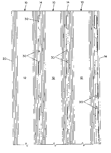
Fig. 1 is a top plan view of a section of a floor
mat according to the invention;
Fig. 2 is an end cross-sectional view of a rail
of the mat shown on a larger scale than Fig. l; and
Fig. 3 is an end view of a section of the mat and
shows on the left side how the adjacent rails
articulate when the mat is rolled upO
:; :
~escription of the Embodiment
The embodiment closely resembles the floor mat
described and shown in the Bartlett '834 patent, which
is incorporated by refere`nce into the present
specification. In particular, it comprises side-by-
side, parallel rails 10, each of which has a body
portion 12 adapted to receive a tread element 13 (see
Fig. 3) and an integral coupling portion 14 by which
it is joined to an adjacent rail through a ball and
; socket arrangement. Each rail is of uniform cross-
section along its length and is produced by extrusion.
The body has a recess 16 opening upwardly and defined
on either side by an overhanging lip 18. The lips
retain a carpet strip or some other form of tread
element 13 in the rècéss, as is well known Per se.
On one edge of the rail member body is a flange
portion 20 of generally C-shaped cross-section that
defines a socket 22. A connector formation 24 on the
coupling portion 14 in the general shape in cross-
- ~31~924
,
section of a ball fits into the socket 22 of the
adjacent rail. The opening slot 26 of the socket 22
is wider than the web part 28 of the coupling portion
14 of the rail, which allows each rail to articulate
about the longitudinal axis of the ball and socket
coupling when the mat is rolled up. The web part 28
has elongated holes 30 uniformly spaced along its
length for passage of dirt and water removed by the
treads of the mat to the floor or other surface on
which the mat is placed in use. Longitudinal ribs 32
on the marginal upper surfaces of the rail body assist
the tread elements in removing dirt and impart a non-
slip characteristic. As described thus far, the
embodiment employs well-known features of floor mats
that have enjoyed considerable commercial success and
have met a need for a durable, attractive, economical
and easy-to-use entrance mat.
In accordance with the present invention, the
rails 10 are made by coextrusion of different
thermoplastic polymeric materials, the differently
cross-hatched regions of Fig. 2 representing those
different materials. The body portion 12 and
connector portion 14 are both formed of a rigid high-
impact strength thermoplastic polymeric material. A
polymeric material having an Izod impact strength,
1~8th inch notch, of not less than 16 ft./lb./in., a
Shore D hardness of about 80 and a tensile yield
strength of at least 6000 psi is preferred. Acrylic-
modified polyvinyl chloride polymers with these
properties are commercially available.
The lower extremities 34 of the three ribs or
feet 36 of the rail, which support the rail on the
floor, are made of a soft, compressible thermoplastic
polymeric m2terial to provide a cushioning effect and
impart a non-sIip characteristic. A polymeric
material having a modulus of rigidity less than 16,000
psi at -49F, a percent elongation of more than 300
- and a Shore A hardness o~ between 60 and 80 is
,:
,,.,,",,. :
1 31 ~92~
--6--
preferred. Commercially available acrylic-modified
polyvinyl chlorides with these properties are
suitable.
The coupling portion 14 of the rail is joined to
the body portion 12 by a living hinge portion 38,
which is in the form of a longitudinally continuous
thin strand of a soft, flexible thermoplastic
elastomer compound that exhibits high endurance to
flexural fatigue. Thermoplastic elastomers suitable
for living hinges, such as polyurethane elastomers,
are commercially available. It is preferred that the
elastomer have an elongation of at least 500%, a
modulus of rigidity at -45F of less than 1750 psi and
a Shore A hardness in the range of 60 to 80. The
tensile strength should be as high as possible, say at
least 3000 p~i at yield. Of course, the flexural
endurance to withstand many hundreds of cycles of
rolling and unrolling of the mat is essential.
As is known per se, the living hinge portion 38
is of hour-glass shape, which creates a zone of
bending without stress risers and comparatively large
areas of joinder to the adjacent rigid parts. The
configuration of the embodiment, in which the rigid
portions joined by the living hinge portion are offset
vertically, is merely exemplary. The living hinge may
be interposed anywhere in the transverse gap between
the rail body 12 and the rigid coupling ball portion
Z4. For example it may be located immediately
adjacent the ball portion 24 or interposed in the web
portion 28. The top flange 40 with the ribs 32 is not
essential to the rail structurally or functionally,
- and the web 28 could extend hori~ontally all the way
from the ball 24 to the body 12, in which case the
living hinge could be at the juncture of the body with
the web or could be anywhere along the width of the
web. More than one living hinge could be provided in
the gap between the coupling portions. It is
preferred, however, that the living hinge not be in
,, .
1 3 ~
line with the holes 30 (which, incidentally, are
punched out of the extruded member) because they would
then be segmental and more prone to failure. The
illustrated embodiment includes the upper flange 40 as
a desirable appearance feature - as seen from the top,
the rails are symmetrical. Finally, the compound used
for the living hinge may be transparent, in which case
it is desirable that it be largely invisible, lest it
be perceived as a gap (though it is very small and not
likely to be observed in use, no matter where it is
~- located).
Except for the living hinge portion, the rails
can be pigmented or dyed in any desired color. The
color extends throughout the material, so scratches
; 15 and other surface damage will hardly show. For
outdoor use, UV inhibitors should be incorporated.
The mat is assembled by sliding successive rails
endwlse onto the last rail o~ the partly assembled
mat. One or more fusion joints (not shown) is made
between the ball~and-socke~ elements of each juncture
between rails to join the~ against lengthwise relative
~; movement. In regions near the fusion joints, the
balls and sockets cannot articulate, and rolling up of
~'~ the mat is permitted by ~lexure of the living hinge.
In regions of the juncture~ remote from the ~usion
joints, rolling up of the m~dt is afforded by a
combination of flexure of the living hinges and
arti~culatlon of the baIl and socket joints. The
j moderate flexibility of the polymeric materials of the
30 ~ma~t~aEfords moderate deformation~of the coupling
portions of the rails, which in turn progressively
diminishes the effect o~ the rotational restraints of
the fusion joints, the greater the distance from the
fusion joint. The moderate flexibility of the
polymeric materials;also allows the rails to conform
somewhat by flexure to irregular surfaces in the
lengthwise direction. The living hinges and ball and
socket joints readily allow conformity to the
:'' ' - ,
, . :~ ,~, . . . .
:: '
31~92~
--8--
- supporting surface in the transverse direction. The
soft thermoplastic on the feet of the rails also
provides local compliance with slightly rough or
uneven surfaces.
~, .