Note: Descriptions are shown in the official language in which they were submitted.
1 - ~ 3~59~0
The invention relates to a process for
reducing cycle time in the moulding of fibre-reinforced
thermoset articles.
Various moulding methods are discussed in
chapters 4 and 5 of the book entitled, Handbook of
Reinforced Plastics, Society of the Plasti~s Industry,
-
Inc. copyright 1964, published by the Reinhold
Publishing Corporation, Library of Congress Catalog
Card No. 64-15205. Whenever contact moulding, bag
moulding, or similar procedures are being used to
fabricate articles of manufacture formed from fiber-
reinforced resins, single die moulds will typically be
, requlred.
To economically produce these articles using
any type of mould, the rate of article production must
be maximized to allow the quick recovary of the capital
costs associated with the purchase of the mould. The
mould c~cle time must be minimized.
In the case of an article that incorporates
fibers or filaments within the hardenable liquid, it is
desirable to quickly wet these materials. In the case
of an article that comprises a fibre reinforcement
matrix and it is desirable to have the thermosetting
resin composition flood all internal voids and inter-
stices within the matrix quickly such that the curing
time of the resin may be kept to a minimum.
A process therefore needs to be developed
that permits rapid flow of the resin into the mould and
which permits rapid wetting of these fibers.
~ The present invention provides a process for
moulding a thermoset article of manufacture including
the steps of:
~ - providing a mould having a surface, said
mould surface having at least one opening defined
downwardly therein,
- locating deflatable member means within
said opening, said deflatable member means having a
'
,,. ~, .
` ~ ~
- 2 ~ 9 ~ 0
fluid chamber containing fluid defined in the interior
thereof, said deflatable member means having a moveable
wall formed between a portion of said fluid chamber and
a moveable wall surface of said deflatable member means
located adjacent said mould surface,
- placing fluid movement means in cornmunica-
tion with said fluid chamber,
~ inserting a preshaped member of fibre-
reinforcement matrix in the mould,
- closing the mould,
- removing fluid from said fluid chamber 50
as to move said moveable wall inward a selected dis-
tance relative to said mould surface, thereby defining
a channel to permit flow of thermosetting resin compo-
sition through said channel into the mould,
- adding fluid to said fluid chamber to move
said moveable wall surface flush with said mould
surface,
- retaining said thermosetting composition in
said mould for a sufficient period to dimensionally
stabilize the article of manufacture,
- opening the mould and removing said article
from said mould.
These and other features and advantages or
the present invention will become apparent from the
following detailed description, wherein reference is
made to Figures 1 and 2.
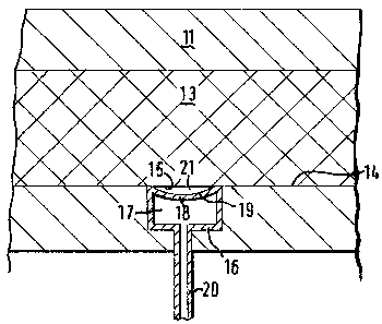
Fig. 1 is a schematic representation in a
side view in partiale cross section showing the deflat-
~0 able ~member positioned within an opening defineddownwardly within the mould section.
Fig. 2 is a schematic representation in a
side view and partial cross section of the same deflat-
able member now ~efining a channel for ~low of a
hardenable liquid beneath the preshaped filament
member.
'
.,.,.,,~,~. , ~.
_ 3 _ ~3~940
In Figs. 1 and 2, 11 and lZ represent the
upper and lower parts of a mould, respectively, 13
represents a preshaped member of reinforcement fibre
matrix.
The mould can be seen to comprise a surface
14 having at least one opening 15 defined ~ownwardl~
therein. Surface 14 of the mould preferably coincides
with the lower surface of the preshaped member of
fibre-reinforcement matri~. Opening 15 can be embodied
in the form of a longitudinal groove which in the
figures is shown in cross-section. More than one
groove can be present in the lower mould surface. The
mould is referred to in a generic sense wherein it is
understood to include structures associated with vacuum
bag moulding, pressure bag moulding autoclave moulding,
vacuum injection moulding, cable clave moulding or the
like.
Deflatable member means 16 are located within
the opening 15, which comprise in a preferred embodi-
ment a tube fitting in the groove and having a rect-
angular cross-section made from rubber or other elasto-
meric material. A fluid chamber 17 is provided in the
interior of member 16. The deflatable member means 16
can be seen to have a moveable wall 18 formed between a
portion o~ the fluid ahamber 17 and wall surface 19
which is located adjacent to mould surface 14.
Fluid chamber 17 is connected via tube 20 to
a pump (not shown) and reservoir (not shown) that are
~ used to supply and remove fluid to and from deflatable
member means 16.
Fig. 1 shows the fluid chamber 17 in the
nflated state, when fluid 22 is supplied, the moveable
wall 18 is caused to move upward to a position wherein
surface 19 is flush with surface 14 of the mould.
Withdrawal of fluid from chamber 17 causes wall 18 to
move downward to the deflated position shown in Fig. 2,
thus defining a channel 21 through which thermosetting
:,.~.,.,. ~. .. .. . . .
- 4 - 1~159~0
resin can be supplied to the interior of the mould to
fill the internal voids of the fibre matrix.
Suitable thermosetting resins are selected
from polyester resins, phenolic resins, vinyl ester
resins, epoxy resins, polyurethane resins, polyiso-
cyanurate resins, urethane resins, and polyamide
resins.
The fibre matrix can comprise fiberglass
cloth, tape, woven roving, or any other collection of
fibers, cloth, or material used to reinforce the resin.
Preshaping to closely fit the internal volume of the
mould can be carried out by any known method, compress-
ing being preferred. The flow of the thermosetting
resin beneath certain portions of the filament matrix
accelerates supply of resin to the filament- matrix
thereby allowing shortening the moulding cycle time.
Wall 18 may be formed by a co-extrusion
technique wherein a material such as nylon may be used
to form the outer surface of the wall, to allow the
wall to easily part from the finished article. In
addition, mould-release agents may be employed.
The moulding may comprise at least one
thermosetting resin injection port typically located
centrally within the lower surface area of the mould.
To allow the rapid supply of the resin over a rela-
tively large portion of the lower mold surface area the
deflatable member means 16 preferably extend radially
outward away from that port. It should be well recog-
nized that many other flow patterns may be used to30 accomplish the same mechanical result. For example,
the deflatable member means may comprise a series of
linear parallel fluid chambers, evenly spread over the
lower surface area of the mould.
.. : , ,, . ,; . . ~ , j . . . . .