Language selection

Search

Patent 1315953 Summary

Third-party information liability

Some of the information on this Web page has been provided by external sources. The Government of Canada is not responsible for the accuracy, reliability or currency of the information supplied by external sources. Users wishing to rely upon this information should consult directly with the source of the information. Content provided by external sources is not subject to official languages, privacy and accessibility requirements.

Claims and Abstract availability

Any discrepancies in the text and image of the Claims and Abstract are due to differing posting times. Text of the Claims and Abstract are posted:

  • At the time the application is open to public inspection;
  • At the time of issue of the patent (grant).
(12) Patent: (11) CA 1315953
(21) Application Number: 1315953
(54) English Title: COUNTERGRAVITY CASTING APPARATUS
(54) French Title: APPAREIL DE COULEE PAR ASPIRATION
Status: Expired and beyond the Period of Reversal
Bibliographic Data
(51) International Patent Classification (IPC):
  • B22D 18/06 (2006.01)
(72) Inventors :
  • MERCER, JAMES B. (United States of America)
  • VOSS, KARL D. (United States of America)
(73) Owners :
  • GENERAL MOTORS CORPORATION
(71) Applicants :
  • GENERAL MOTORS CORPORATION (United States of America)
(74) Agent: GOWLING WLG (CANADA) LLP
(74) Associate agent:
(45) Issued: 1993-04-13
(22) Filed Date: 1988-05-20
Availability of licence: N/A
Dedicated to the Public: N/A
(25) Language of filing: English

Patent Cooperation Treaty (PCT): No

(30) Application Priority Data:
Application No. Country/Territory Date
077,891 (United States of America) 1987-07-27

Abstracts

English Abstract


C-3958
F-509
COUNTERGRAVITY CASTING APPARATUS
Abstract of the Disclosure
Apparatus for the shaping of metal in a
bottom-gated mold by the vacuum induced countergravity
casting method including an upstanding levee on the
periphery of the drag and circumscribing the
chamber-to-mold joint and/or the cope-to-drag joint for
isolating such joint(s) when the mold is immersed in an
underlying melt.


Claims

Note: Claims are shown in the official language in which they were submitted.


The embodiments of the invention in which an
exclusive property or privilege is claimed are defined
as follows:
1. Apparatus for shaping a metal article in a
bottom-gated mold by the vacuum-induced, countergravity
casting method wherein the mold is immersed in an
underlying melt of said metal and evacuated to draw
said melt up into said mold, said apparatus comprising:
a gas-permeable cope portion of said mold
defining a mold cavity for shaping said
article, said cope portion having a peripheral
edge defining a first sealing face on its
underside between said edge and said cavity;
a drag portion of said mold further defining
said cavity and having a second sealing face
on its topside surrounding said cavity;
means for sealingly engaging said first and
second sealing faces one to the other at a
parting line therebetween;

a flange on said drag portion extending
outboard said second sealing face beyond said
peripheral edge, said flange having a
substantially flat upper surface portion and
an upstanding levee portion circumscribing
said upper surface portion to substantially
isolate said upper surface portion from said
melt when said mold is immersed in said melt;
a vacuum chamber atop said drag portion and
enclosing said cope portion, said chamber
having a lip on its underside sealingly
engaged with said upper surface portion; and
means for evacuating said chamber sufficiently
to draw said melt up into said mold when it is
immersed in said melt.
2. Apparatus for shaping a metal article in a
bottom-gated, expendable shell mold by the
vacuum-induced, countergravity casting method wherein
the mold is immersed in an underlying melt of said
metal and evacuated to draw said melt up into said
mold, said apparatus comprising:

a cope portion of said mold comprising a
gas-permeable, resin-bonded-sand shell formed
by molding against a cope-shaping pattern,
said cope portion defining a mold cavity for
shaping said article and having a peripheral
edge defining a first sealing face on the
underside of said cope portion between said
edge and said cavity;
a drag portion of said mold comprising a
resin-bonded-sand shell formed by molding
against a drag-shaping pattern, said drag
portion further defining said cavity and
having a second sealing face on its topside
surrounding said cavity;
means for sealingly engaging said first and
second sealing faces one to the other at a
parting line therebetween;
a flange on said drag portion extending
outboard said second sealing face beyond said
peripheral edge, said flange having a
substantially flat upper surface portion and
an upstanding levee portion circumscribing
said upper surface portion to substantially
isolate said upper surface portion from said
melt when said mold is immersed in said melt,
said upper surface and said levee portions
being formed against said drag-shaping pattern
at the time said drag portion was molded;

a vacuum chamber atop said drag portion and
enclosing said cope portion, said chamber
having a lip on its underside sealingly
engaged with said upper surface portion of
said flange; and
means for evacuating said chamber sufficiently
to draw said melt up into said mold when it is
immersed in said melt.
3. Apparatus for shaping a metal article in a
bottom-gated mold by the vacuum-induced, countergravity
casting method wherein the mold is immersed in an
underlying melt of said metal and evacuated to draw
said melt up into said mold, said apparatus comprising:
a gas-permeable cope portion of said mold
defining a mold cavity for shaping said
article, said cope portion having a peripheral
edge defining a first sealing face on its
underside between said edge and said cavity;
a drag portion of said mold further defining
said cavity and having a second sealing face
on its topside surrounding said cavity;
means for sealingly engaging said first and
second sealing faces one to the other at a
parting line therebetween;

11
a flange on said drag portion extending
outboard said second sealing face beyond said
peripheral edge, said flange having an
upstanding levee portion thereon
circumscribing said second sealing face to
substantially isolate said parting line from
said melt when said mold is immersed in said
melt;
a vacuum chamber atop said mold confronting a
substantial portion of said cope portion, said
chamber having a lip on its underside
sealingly engaged with said mold; and
means for evacuating said chamber sufficiently
to draw said melt up into said mold when it is
immersed in said melt.
11

Description

Note: Descriptions are shown in the official language in which they were submitted.


~31~
C-3958
F-509
COUNTE:RGRAVITY CASTING APPARATUS
This invention relates to apparatus for the
vacuum-induced, countergravity casting of metal in
gas permeable mold~ and, more particularly, to means
for isolating the cope-to-drag and vacuum
chamber to-mold seals from the underlying melt.
Background of the Invention
The vacuum-induced, countergravity, casting
process is useful in th~ maki~g of thin-wall~d
near-net-sh~pe castings and involves: sealing a
bottom-gated mold, having a gas-permeable upper
portion, to the mouth of a vacuum chamber such that th~
chamber confronts the upper portion; immersin~ the
underside of the mold in an underlying melt; and
evacuating the chamber to draw melt up into the mold
through one or more of the gates in the underside
thereof. Such a process is shown in U.S. patent
Chandley et al 4,340,108, issued July 20, 1982, wherein
the mold comprises a re~in-bonded-sand shell having an
29 upper cope portion sealingly bonded (e.g., glued~ to a
lower drag portion and the vacuum chamber se~lsd atop
: the cope such that the parting line between the cope
and drag lies outside the vacuum chamber. U.S. patent
~ : Almond 4,632,171, issued Dece~ber 30, 1986, a~signed ~o
: 25 the assignee of the present invention, is an
i~provement on Chandl~y et al 4,340,10B and seals the
mold to the vacuu~ chamber atop the drag such tha~ the
: par~ing line between the oope and drag falls within the
vaeuum chamber. In such processes, it is desira~le to
~30 imme~s~e the ~rag as far as possible into the melt to
prevent invasion of the mold cavity by air being sucked
..... .

1 3~5~
through any portions of the porous draq which mighS be
above the ~elt surface. Hence, in both the Ch~ndley et
al and Almond cases, the parting line between the cope
and the drag i5 brought into close proximity to the
surface of the und~rly~ng melt during casting.
Moreover, in Almond's case, the seal bztween the vacuum
chamber a~d the mold i5 also brought into close
proxim;ty to the surface of the underlying melt during
immer~ion.
It is undesirable to have melt contact either
the parting line between the cope and the drag or the
joint between the vacuum chamber and the mold. In this
regard, melt at the parting line~ can cause
gasi~ication of any glue therein which gases are drawn
into the mold cavity ~nd can be trapped in the casting;
and (2~ can be sucked into the mold cavity at the
parting line thereby ruininy the casting. Moreover,
hot melt at the chamber-mold joint can be sucked
directly into the vacuum chamber causing ignition of
the gases therein and result in destruction of the
mold, casting and possibly the chamber itself.
: : It is not always possible to control precisely
the depth that th~ mold is immersed into the underlyinq
melt. Hence there is a risk tha~t:the cope-to-drag
- 25 pa~ting line and/or the cham~er-to-mold joint may
: accidentally be contacted by the~hot ~elt unless some
:technique can ~e devi ed for isolating them from the
:melt under all circumstances.
: It is an object of:the present invention to
provide improved apparatu~ for the vacuum induced,
countergravity casting of metal into porous,
: 2

1 31~9~
bottom-gated molds wherein the cope-to-drag parting
line and/or the chamber-to-mold joint is isolated from
the melt over a wide range of immersion depths. Thic
and other objects and advantages of the present
invention will become more readily apparent from the
description thereof which follows.
Brie~ Descrlption of the Invention
Essentially the invention comprehends
countergravity casting apparatus of the aforesaid type
wherein the drag includes a peripheral levee
circumscribing the chamber-to-mold joint and/or the
cope-to-drag parting line to prevent melt from the
underlying melt from contacting the joint or parting
line over a wide range of mold immersion depths
including depths where the chamber-to-mold joint and/or
the cope-to-drag parting line are beneath the surface
of the melt during casting. ~he levee formed on th~
drag permits melt to rise high up along the sides of
the mold without invading the parting line or joint and
making deletorious incursions into either the mold
cavity or vacuum chamber. In the case of
resin-bonded-sand molds, the levee will preferably be
formed on the drag by molding against a drag-shaping
pattern ala the drag-forming method of Almond 4,632,171
which is intended to be ineorporated herein by
reference as it relates to such method.
Brief Description of the Drawin~s
The invention will better be understood when
considered in the ligh~ of the following detailsd
description of certain embodiments of the invention
which~are described hereafter in conjunction with the
, .. . . . .

131~
several Figures in which:
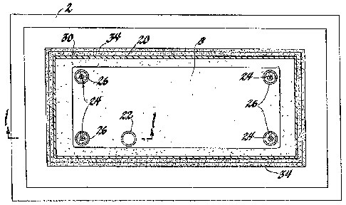
Figure 1 is a partial side sectional view
(i.e., in the direction 1-1 of ~igure 2) through a
vacuum-induced, countergravity metal casting apparatus
in acoordanoe with the present invention;
Figure 2 is a plan view of the apparatus o~
Figure 1 (i.e., in the direction 2-2 of Figure 1); and
Figure 3 is a partial side sectional view,
like that of Figure 1, but of another embodiment of the
present inven~ion.
Description of Specific Embodiments
Figures 1 and 2 show a vessel 2 of metal melt
4 which is to be drawn up into the mold 6. The mold 6
include a gas-permeable, upper (i.e., cope) portion 8
joined (e.g., glued) to a lower (i.e., drag) portion 10
alo~g parting line 12 which defines therebetween a mold
cavity 16. The lower drag portion 10 includcs a
plurality of ingates 14 on the underside thereof for
supplying melt to the mold cavity 16 when the cavity is
evacuated. The drag portion 10 of the mold 6 is sealed
to the lip 18 at the mouth of a vacuum chamber 20 such
that the gas-permeable upper portion 8 is encompassed
by the chamber 20. The vacuum chamber 20 is
communicat~d to a v~c~um source (not shown) via conduit
22. The upper portion 8 o the mold 6 comprise~ a
gas-permeable material ~e.g., resin-bonded-sand) which
permits gaæe~ to be withdrawn ~rom the mold cavity 16
wh~n~a vacuum is drawn in the chamber 20. The lower
portion 10 of the mold 6 may conveniently comprise the
same material as the upper portion 8, or other
mdterials/ permeable or ~mpermeable, which are

13~L3~
compatible with the upper portion material. The mold 6
may be secured to the chamber 20 by means of inverted
threaded shafts 24 which are screwed onto upstanding
mounting lugs 26 in the manner described in V.S. patent
No. 4,658,880 in the name of Karl Voss and as~igned to
the a~signee of the present invention. Othsr methods
of securing the mold to the chamber are acceptable as
well.
The drag portion 10 of the mold 6 includes a
peripheral flange 28 which extends outboard the
peripheral edge 30 of the cope 8. The flange 28
includes: (1) a flat upper sur~ace 32 or sealingly
engaging the lip 18 of the chamber 20 (e.g., via a
Fiberfax lnot shownl insulating material; and (2~ an
upstanding levee 34 circumscribing the upper surface
portion 32 (and henee the joint between the lip 18 and
the sur~ace 32). As shown in Figure 1, the levee 34
permits immersion of the mold so deep in the melt 4
that the joint between the chamber 20 and the surface
32 lies beneath the surface 36 of the melt yet is
isolated from the melt by the levee 34.
Figure 3 depicts another embodiment o~ the
present invention wherein the lip 38 on the mouth of
the chamber 40 sealingly enga~es a 1~t surface 42 atop
~ 25 the cope 44. The cope 44 engage~ the drag 46 along the
parting line 48. The drag 46 has a flange 50 extending
outboard the cope 44 which flange includes an
upstanding levee 52 circumscribing the partin~ line 48
and isolating it fro~ contact with the melt 54 as
de cribed above.
: While the invention has been disclvsed in
: 5
:

13~59~3
terms of specific embodiments thereof it is not
intended to be li~itçd thereto hut rather only to the
extent set forth hereafter in the slaims which follow.
,
: - 25
:
~ 30
., ~ , ,

Representative Drawing
A single figure which represents the drawing illustrating the invention.
Administrative Status

2024-08-01:As part of the Next Generation Patents (NGP) transition, the Canadian Patents Database (CPD) now contains a more detailed Event History, which replicates the Event Log of our new back-office solution.

Please note that "Inactive:" events refers to events no longer in use in our new back-office solution.

For a clearer understanding of the status of the application/patent presented on this page, the site Disclaimer , as well as the definitions for Patent , Event History , Maintenance Fee  and Payment History  should be consulted.

Event History

Description Date
Time Limit for Reversal Expired 2001-04-17
Letter Sent 2000-04-13
Grant by Issuance 1993-04-13

Abandonment History

There is no abandonment history.

Fee History

Fee Type Anniversary Year Due Date Paid Date
MF (category 1, 5th anniv.) - standard 1998-04-14 1998-03-30
MF (category 1, 6th anniv.) - standard 1999-04-13 1999-03-30
Owners on Record

Note: Records showing the ownership history in alphabetical order.

Current Owners on Record
GENERAL MOTORS CORPORATION
Past Owners on Record
JAMES B. MERCER
KARL D. VOSS
Past Owners that do not appear in the "Owners on Record" listing will appear in other documentation within the application.
Documents

To view selected files, please enter reCAPTCHA code :


To view images, click a link in the Document Description column (Temporarily unavailable). To download the documents, select one or more checkboxes in the first column and then click the "Download Selected in PDF format (Zip Archive)" or the "Download Selected as Single PDF" button.

List of published and non-published patent-specific documents on the CPD .

If you have any difficulty accessing content, you can call the Client Service Centre at 1-866-997-1936 or send them an e-mail at CIPO Client Service Centre.

({010=All Documents, 020=As Filed, 030=As Open to Public Inspection, 040=At Issuance, 050=Examination, 060=Incoming Correspondence, 070=Miscellaneous, 080=Outgoing Correspondence, 090=Payment})


Document
Description 
Date
(yyyy-mm-dd) 
Number of pages   Size of Image (KB) 
Claims 1993-11-09 5 149
Abstract 1993-11-09 1 14
Drawings 1993-11-09 1 41
Descriptions 1993-11-09 6 206
Representative drawing 2001-07-25 1 21
Maintenance Fee Notice 2000-05-10 1 178
Fees 1998-03-29 1 36
Fees 1999-03-29 1 32
Fees 1997-03-26 1 33
Fees 1995-03-29 1 31
Fees 1996-03-28 1 31
Correspondence 1993-01-20 1 34