Note: Descriptions are shown in the official language in which they were submitted.
~ 131~75
LOOM WITH SELECTIVELY POSITIONABI,E SH~lTTI.E
MECHAN I SM
Background Of The Invention
This invention relates generally to improvements in weaving
looms to provide for satisfactory weaving of fabric of selected
widths that may be substantially less than the total width of
the loom. More specifically, the invention relates to an
improvement in such looms providing for selective positioning of
the shuttle mechanism or mechanisms at various locations along
the shuttle raceway.
In recent year n~erous advances in weaving technoloqy and
in the construction of large, heavy dDty looms has permitted the
weaYing of-fabrics, including heavy-fabrics, in ever increasinq
widths. Looms are now available and in use in various weaving
industries, such as those rela ing to the weaving of papermaking
fabrics, that are capable of weaving fabric of 30 meters or more
in width and of indefini~e length. Because of the massive size
and the gxeat strength ~equired for the various components of
such a loom, these very large looms are extremely expensive,
80metLme8 coBting many hundreds of thousands of dollars.
~ccordingly, it is Lmportant to have such looms in operation,
producing salable fabric, to the greatest extent po~sible.
~ ~3~7~
~ecau~e only certain cu~tomers have require~ent~ for as wide as
the largest of these looms, it has ~een difficult to use such
looms to their full capacity. The nature o:E weaving limits the
ability of such large looms to weave fabrics substantially
narrower than the total width of the loom. This i~ because the
shuttle pulling the weft filament back and forth across the
raceway of the loom must maintain sub~tantial tension on that
weft filament at all times to provide a consistently high
quality fabric. ~owever, if weaving of a ~abric substantially
narrower than the total width of the loom is attempted, at each
reversal of the shuttle's movement, there is a brief period when
the weft goes ~lack, thus increasing the potential for
unsatisfactory weaves.
In known looms there has been little that can be done about
this problem because of the massive apparatus $hat is needed to
support and move the shuttle bo~ a~embly, which has reguired
that the shuttle box assemblie~ remain positioned adjacent the
extreme ends of the loom. Thus, the very largest and most
expensi~e looms frequently e~tperience the lowest rates of
utilization in a weaving mill.
:Summa~y__f The~Invention
In order to overcome the disadvantage~ of pre~ent loom~, as
described above, the present invention provides an improvement
: in such looms to enable the weaving of com~ercially satisfactory
fabrics of selected widths subotantially less than the total
length of a particu~ar loom. ~ore particularly, this invention
provide~ for uch an Lmproved loom having a selectively
positionabl~ ~huttle mechanism that may be positioned at any of
~ ~3~6~7~
- 3
a plurality of location~ along the loom raceway. To achieve
these and other ob~ect~ of the i~vention ~hat will become
apparent ~o those ~killed in the art, there i~ provided an
Lmprovement in a loom having a shuttle raceway e~tending acro~
the weaving path of the loom between opposite ends of the loom
weaving surface and in which a shuttle moves reciprocatingly
acros3 the raceway between two shuttle box a~semblies. The
shut~le i5 propelled by picking apparatu~ pvsitioned ad~acent
each ~uch shuttle box a~sembly and the loom include~ ~upport
struc~ure for carryiny the raceway, the shut~le box assemblies
and the picking apparatu~O This improvement compri3es the loom
being configurad for mounting the ~huttle box assemblie~ and the
picking apparatus at any of a plurality of po~itions along the
raceway, whereby the loom may be configured to have a weaving
width substantially narrower than the total width of the raceway
for weaving a fabric substantially narrower than the total width
of the raceway.
Brief De~cr~ tion of the ~rawinq~
Particularly preferred embodiment~ of the apparatus of this
invention will be di~clo~ed in detail in connection with the
drawings in which:
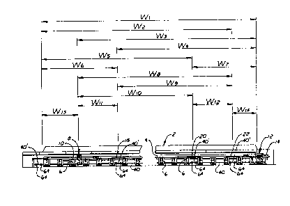
Fig. 1 i8 an elevational view of an Lmproved loom according
to thi~ invention indicating variou~ widths of fa~rics that
could be woven by selective positioning of the ~huttle box
a6se~blies and picking m~chaniam~ according to the invention;
Fig. 2 i an elevational view, at a larger ~cale, of a
shuttle box as~embly and picking mechani~m incorporated into the
L~proved loom of Fig. l;
'
7 ~
Fig. 3 i~ ~ ~ide ~ectional view of the shuttle assembly
~aken along line 3-3 of Fig~ ~, and
Fig. 4 is an al~ernative shuttle box a~s~mbly an~ picking
mechanism for u~e on the improved loom of Fig. 1 in place of
that illu~trated in Fig6. 2 and 3.
A preferred embodi~ent of the application of this invention
i~ illustrated in the schematic front elevation~l vie~ of Fig.
1. In that illustration a large loom 2 i~ illu~trated. This
loom may suitably be any of a number of available looms of
significant width, such as a Texo type HF manufactured by
Almhult~ ~ruk in Sweden, modified in accordance with the present
invention. ~any of the components of thi8 loom 2 are
conventional~ including the reed as~embly 3 (~hown in Fig. 2),
the raceway 4 and support members 6 for supporting ~uch raceway
or race pla~e. There also are provlded for the left hand ~ide
of the Ioom a shuttle box assembly 8 and a picking mechanism 10
along with corresponding right hand side shuttle box a~sembly 12
and picking mechanism :14. The shuttle box a~semblies and
picking apparatus are illustrated in greater dekail in Figs. 2
and 3.
In the improved lo~m of this invention the shuttle raceway
iB fabricated with at least one, and in this case a plurality,
~uch a~ four, portions 16 (not s~own), 18, 20 and 22 being
selectively removable in the illustration of Fig. 1. The
se1ectively removable raceway portion 16 iB not shown, ~ecause
the loom is illu8trated a~ having that portion already removed
; 1 3~ ~7~
and the shuttle box and picking mechanism assemblie~ 8 and 10
mounted in place o f that raceway portion 16.
~ he ~huttle box assembly 8 and pickîng mechanism lo are
illustraked more clearly in the enlarged fragmentary view of
E~ig. ~. While this figure illus~rates the shut~le box ~ssembly
8 and picking mechanism 10 associated with th~ le~t hand side of
the loom in Fig.l, it is to be under~tood that the ~huttle box
assembly 12 and picking m~chanism 14 are substantially identical
in structure and function, but reversed in orientation f~r use
on the right hand sid~ of the loom.
This shuttle box assa~bly 8 includes a plurality (three in
this preferred embodimen~) of shuttle cell~ 24, 26 and 28, each
of which include a shuttle braking mechanism 30, for stopping
movement of a shuttle 32 received therewithin after its passage
along the raceway. A conventiona~ and well known mechanism 34,
such as an air cylinder, is provided for selectively moving the
respective ~huttle cells to bring a chosen such cell 24 into
ali~nment with the path of a shuttle 32 moving along the raceway
~or receiving the shuttle. Selectively, this shu~le box 24 may
be moved out of the ~huttls receiving po~ition in alignment with
the ~huttle path to another position, such as by generally
vertical movemeIlt in the illustration of Fig. 2, 30 that one of
the othsr ~huttle cells 26 and~28 may then be mo~d into shuttle
receiving posi~ion. The control~ for thi~ ~huttle cell moving
mechanism may con~eniently be any of those types of structureR
that are conventional and well known in the art. ~he shuttle
cell moving mechanism 34 conveniently may be mounted to backing
member 36 that i8 supported by the loom structure. As shown
most clearly in Fig. 2, this backing member 36 may be mounted to
,
:.
0 7 ~
the overall loom structure by a pivotal mounting comprising
bearing blocks 38 affixed to the backing me.mber 36 and having
journaled therewithin portions of the shaft 40 ~hat is carried
by the main supporting frame 42 of the loom. Thi~ ~ournalling
enables ths backing member 36 to pivot about the axi~ of that
shaft 40 during the beating-up action of the lo~m, a~ indicated
by the angled broken line repre~entation of Fi~. 3. Actuating
mechani~m 34 i8, in turn, mounted to the bac~ing member 36.
Convenien~ly, this mounting may be by means of a shaft 44
affixed by 6uitable brackets 46 to backing me~ber 36 and
received through a journal 48 that may be po~itioned at the
lower end of the actuating mechanism 34~
As ~hown in Fig~. 2 and 3 the shuttle cells 24, 26 and 28
that compri~e a portion of the shuttle box a~embly preferably
are joined together to form a ~ubstan~ially uni~ary three cell
shuttle box, generally indicated ~y reference numeral 50.:
Conveniently, an actuator portion, ~uch a8 piston rod 52 of the
actuator a~sembly 34 is affixed in a conventional manner to the
shu~le box 50, ~uitably adjacent the bottom thereof. This
shuttle box 50 i6 also ~upported for reciprocating movement
generally parallel to backing member 36 by con~entional means,
~uch a~ guide member~ 54 affixed to the backing me~ber 36 and
slides 56, ~uch as ball bushings, affixsd to the shuttle box 50.
~his provides for smooth and reIatively low friction
reciprocati~g movement of the ~huttle box 50 parallel to the
backing member 36, a~ indicated by the broken line
representation in Fig. 3.
A~ best shown in Fig. 2, the aupport members 6, in addition
to supporting a portion of the raceway 4, al~o support the
" .
~ 3 ~
picking mechanism 10. These supports 6 are al~o mounted to the
loom for pivo~ing movement during the beating-up proces~,
suitably by mean~ of bearing blocks engaging shaft~ 40 in the
manner ~imilar to that described with respect ~o the backing
member 36. Thi~ i~ conventional in loom con~tructien and is not
illustrated in detail. This picking mechani~ lO ~uitably may
comprise an accumulator ch~mber connected to a conventional
source of pres~uri~ed fluid and connected in turn to a fluid
operated cylinder 60, which may be either hydraulic or
pneumatic, with the actuating piston rod of that cylincler S0
having on its outer end a picking member 62 for engaging and
launching the shuttle 32 along with raceway 4 under the
influence of pressurized fluid rQleased from the accu~ulator 58
into the cylinder 60. Cylinder 60 may also be attached to
backing member 36 in a conv0ntional manner ~o that both tha
picking mechanism cylinder 60 and the ~huttle box aæsembly 8
will move in unison during the beating-up proce~. A~ indica~ed
in ~i~. 3, actuatien of the ~huttle box actuating mechanism 34
can serve to align any of the ~huttle box cells 24, 26 or 28
with the cylinder 60 and picking me~ber 62 so that a shuttle
held in any one of those shuttle cells may be launched along the
raceway 4 when de~ired.
Some of the a~vantages of the loo~ construction of this
invention are illu~trated in ~ig. 1. By providing the ~haft 40
with conventional coupling~ con~ecting short re~ovable sections
of that sh~t 40' with the remainder thereof, any one of those
sections 40' may be re~oved for mounting of the b2cking member
36 in it~ placet in the manner illustrated in detail in Fig. 2.
Thu~, by providing the ~electively removable portions 16, 18, 20
.,
,',
~ 31 6~7~
and 22 of the raceway generally super~acent tho~e removable
shaft por~ions 40'~ any one of tho~e raceway ~ection~ and the
corresponding shaft section~ may be removed and the shuttle box
assembly 8 and picking mechanism 10 illu6trated in Figs. 2 and
3 may be inserted therefor, to define the effec~ive left hand
side o the weaving path of the loom. Corre~pondingly, the
right hand ~ide of shuttle box as~embl~ 12 and picking mechanism
14 may conveniently b equivalent to a mirror Lmage of the left
hand side shuttle box as~embly and picking mechanis~ illustrated
in Figs. 2 and 3. Thus, this right hand side of shllttle bo~
assembly 12 and picking mechanism 14 may also be in~erted in
place of any of the removable raceway ~ection and shaft portion
to po~ition the effective right hand ~ide of the weaving path at
any of those po~itions. Thus, the total width of the weaving
path for this one loom may ea~ily be changed to any of those
widths W-l ~hrough W-14 shown on Pig. 1 ~hile ~aintaining the
necessary tension in the weft filament durin~ the weaving
proce~s and thus maintaining the quality of the weave. In thi~
manner even a very laxge loom, ~uch as one haYing a weaving
surface width of 30 meters or more may enjoy far greater
utilization, because it may con~eniently be adapted for weaving
fabrics of many different, smaller widths of the weaving path.
This is a major advan$age not po~sessed by conventional looms in
which the ~huttle box assemblies and picking me~hanisms are
permanently mounted to the extreme ends of the weaving path.
In the fragmentary perspective view of Fig. 4, there i~
illu~trated a second preferred embodiment of the improved loo~
o f thi8 inv~ntion. While this embodiment i8 illustrated a~ the
unit ~or the right hand end of the loom 2 of Fig. 1, in;place o
'
13~6~7~
huttle box assembly 12 and pickinq mechanism 14, it is o be
under~tvod that a unit that is generally a mirror Lmage of thi~
sa~e unit could be u~ed on ~he left hand s:ide of the loom, in
place of shuttle box assembly 8 and picking mschanism 10. This
additional embodLment has ~he added advantage of being usable
without requiring the removal of any section of the loom frame
or raceway. Thus, this improved ~tructure may be incorporat~d
as a portion of either conven~ional loo~l~ or loom~ having
removable raceway sections a~ with the pxeviously described
embodiment.
In this second embodiment a plurality of shuttle box cells
(in this case, four) is provided in which each of the cells is
spaced radially about a predetermined axis 118 that e~tends
through the shuttle box assembly. Preferably, as æhown, each of
the shuttle cells is spaced equidistant about said axis 118.
~he inner ends of these shuttle cells are positioned close to
the outer end of the loom reed asse~bly 103. Preferably, al50,
~he shuttle cells 122, 124, 126 and 128 may be mounted to
support members 134 and 136 that are carried by a shaft 138 that
is collinear with axis 118 and i8 attached to a conventional
Btepping type rotary drive meohanism 140. In this embodiment in
which four shuttle cells are spaced equally about and parallel
to the axis lI8, with one centered in each quadrant, the stepper
mechanism 140 may:be a conven~ional unit configured to effect
select,ive rotation of the rotary motion output member or shaft
138 in 90 increments in a manner weIl known in the art. ~his
stepper mechani~m is affixed to a mounting member 142 that is
reciprocatingly movable in the direction shown by the arrows
adjacent that member 142~ preferably in a generally vertical
"
''
~31 6~75
1~
direction toward and away from the raceway 104. Such movement
may be guided by affixing to the mounting member 142 a plurality
of guide~ 144, such as ball bu~hings, that translatinyly engage
guide members 146 that are affixed to membeI 148. Also affixed
to member 148 may be an actuator 150, such a~ a conventional
pressurized fluid actuated cylinder ha~ing a piston rod 152 that
moves in a direction ~oward and away from the mounting member
148. ~he upper end of ~hi~ piston rod is attached to the rotary
actuator mounting member 142 ~o that extension of the piston rod
152 will raise the member 142, its attached rotary actuator 140
and thus the plurality of shuttle cell~ away from the raceway
104, for purposes to be described below. Thu~, in this
embodiment the ~huttle box a~sembly comprise~, es~entially, the
plurality of shuttle cells, the rotary drive and mount, and the
~upporting and actuating apparatus for carrying tha~ rotary
drive and ~oving it toward and away from the raceway 104 by
pre~elected distance~. This ~huttle box assembly 112 ma~
con~eniently be affi~ed to a housing 154 that is removably
attachable at any of a plurality of preselected po~ition~
longitudinally of the raceway 104. This housing 154 may be so
selectively and removably a~tached to the raceway 104 by either
clamp8 or bolt~ or other con~entional structure.
Suitably carried within the housing 154 may also be a
picking mechanism utilizing a pre~surized fluid cylinder
generally sLmilar to the cylinder 60 illustrated in Fig. 2 with
respect to the previous embodiment. A picking member 162 is
~hown in phantom in Fig. 4 engaging the end of a shuttle 132 in
a manner exactly analogou~ to that illustrated in Fig. 2. By
actuation of the picking cylinder and its picking member lfi2,
13~ ~7~
the shuttle 13~ carried within ~huttle cell 124 may be launched
along the raceway 104.
Operation of the shuttle box as~e~bly of the embodLment of
Fig. 4 may now be seen. At 6uch time a~ it is desired to
utilize a shuttle other than ~huttle 132 that: i~ received within
the shuttle cell 124 aligned wi~h the raceway 104, another
shuttle cell, such a6 cell 126, may be provided wîth an
additional shut~le and brough~ into position with re~pec~ to ~he
raceway 104 as follows;
At a tLme when the beating up motion of the loom is
stopped, the actuator 150 may be energized to urge the piston
rod 152 generally upwardly, lifting the member 142 and its
attached rotary actuator 140, along with the mounted shuttle
cells, generally upwards and away from the raceway 104 by
preselected di~tances. This distance need onl~ be that
sufficient to permit rotation of the mounted shuttle cell abou~
the axis 118 without in erference between any portion of ~uch a
shuttle cell and the raceway 104. As the stepper mechani~m 140
i5 actuated, the entire assembly of ~huttle cells is rotated,
suitably 90. ~his then brings the shuttle cell 126 into a
position aligned with and ~paced slightly above raceway 104.
Then the actuator 150 i8 de-energized, or energized in the
opposit direction, bringing the entire fihuttle box asse~bly
down into a po~ition where ~huttle cell 126 i~ aligned in just
the position previously occupied by shuttle cell 124 a has been
illustrated in Fig. 4. ht thi~ time a ~huttle within that
~: ~shuttle cell 126 is al80 align~d with the picking member 162 ~o
that actuation of the picking mechani~m (not shown in this
:
~3~7~i
embodLmen~) will l~unch the shuttle from cell 126
reciprocatingly along the raceway 1040
For clarity of illustration ~he variou~ hoses or cables
bringing pressurized fluid or electric curren~ to the various
actuating me~bers and elements have been omitted, because such
structures are conventional and well known in the art, as are
the device~ utilized for con~rolling ~uch actuator~ and
synchronizing them wi~h movement of the loom. Obvieu~ly,
corxe~ponding further actuation of the variou~ elements of the
e~bod~ment of Fig. 4 may serve to bring other of the shuttle
cells into alignment with the raceway 1~4.
For each of the shuttle cells 2~, 26 and 28 in the
embodiment of Fig. 2 and the shuttle cells 122, 124, 126 and 128
in the embodi~0nt of Fig. 4, there i~ provided a brakiny
: mechanism for halting movement of a ~huttle that ie receivad
within ~hat cel l . ThiR braking mechanism i8 generally
illustrated by the reference numeral 30 in Fig. ~ and the
reference numeral 130 in Fig, 4. Such braking mechanism may
suitably compri~e, in general term~, an inflatable bladder
extending through at least one wall of each such shuttle cell
and having a leather me~ber attached thereto. B~ this structure
inflation of the bladder will urge the leather member inwardly
of the shuttle cell, thu~ providing for frictional engagem0nt
and thus braking of movement of a ~huttla, ~uch a~ shuttle 32 or
shuttle 132. Upon release ~f the pres~ure effecting inflation
of that pres3urized bladder, the shuttle cell is then free to
move generally longitudinally of the shuttlQ cell for ~ubsequent
launching back in the direction from whence it came. ~y using
~uch pre~surized fluid bladder for the braking ~lechan:ism, the
.:,
""'
:~3~7~
only 6tructure nece~ary for connecting that braking mechanism
to the remainder of ~he loom is a ~et of flexible hose~
connected to a controllable supply of pressurized fluid.
Likewi~e, the opera~ion of the remainder of the shuttle box
asqembly and the picking apparatus conveniently is effected by
~uch pressurized fluid carried through flexible ho~es. This
provides for co~venient positioning of this apparatus at any of
the selected locations along the weaving width of the loom.
While the foregoing has de~cribed two particularly
preferred embodLments of the apparatu8 of this invention, it is
to be understood that numerous other embodim~nts, all within the
scope of this invention will readily occur to those ~killed in
the art. Accordingly, the foregoing i8 meant to be illustrative
only of th~ principle~ of the invention and i8 not to be
considered limitative thereof. The scope of this invention is
to be deflned solely by the claim~ appended hereto.
: