Note: Descriptions are shown in the official language in which they were submitted.
~ The invention relates to a closure system, a lighting
unit consisting of two container parts joined together and a
method for closing such a lighting unit. For the purposes of
the invention, a closure system is understood as meaning the
tight joining of two container parts of a closed container.
The most frequent traditional method of joining two container
parts to form a closed container is to weld these container
parts to one another.
If it is desired to be able to open and close a joint or
a closure, for example, the edges of the container parts are
provided, along their opening line, with flanges, which are
joined to ~ne another by means of screws. 0-rings are often
then placed between the flanges, as a seal. Such a joint is
time-consuming to produce and the procedure is unpleasant,
particularly in the open when exposed to wind and weather.
Corrosive environmental effects frequently cause damage to
the screw connection, so that the latter is difficult to
separate and/or difficult to join again. Furthermore, the
position of the 0-ring in the screwed state cannot always be
checked, with the result that it may be slightly pinched and
cease to perform its sealing function.
In order to be as economical as possible with the
screws, frequently screws are provided only at a few points,
with the results that, when the parts are firmly screwed
together, the container parts may exhibit distortions and
hence leak at these few points.
The problem of time-consuming joining and of corrosion
damage to screw connections is avoided, for example, ~y a
solution according to U.S. Patent 4,031,382, in which a
lighting unit is provided with a snap-on connector which is
capable of joining one container part to the other via a
1 3 ~
-- 2 --
toggle lever system and via hooks and straps. However, the
other problems mentioned, in particular the tightness, are
not eliminated by this solution. Moreover, the mounting of
hooks and straps during production of the containers is very
time-consuming and therefore expensive.
The invention provides a closure system which can be
mounted rapidly, is insensitive to corrosion, provides
tightness which can be checked, can be removed rapidly at any
time and can also be mounted again.
More particularly, in one aspect, the invention provides
a casing for an air field light comprising a rigid container
consisting substantially of first and second parts, each said
part having a flange portion, said flange portions being
connected to one another so as to seal the container; and a
shrink sleeve surrounding said flange portions and providing
a water-tight seal of said first and second parts.
In preferred embodiments of this aspect, the invention
provides:
The above casing, further including a layer of sealing
material disposed between the container and the shrink
sleeve; and wherein the layer of sealing material is a hot
melt adhesive.
The above casing, wherein at least one collar-like
projection having a closed annular configuration is defined
along an opening line of at least one of said flange portions
of said first and second parts.
~; LB~
~. 3 ~
- 2a -
The above casing, wherein said flange portions have
screwthreads defined thereon.
The above casing, wherein said flange portions have at
least three bayonet-like catches mounted thereto and
corresponding closing orifices.
The above casing, wherein at least one of grooves and
ribs are defined adjacent and substantially parallel to said
flange portions on a surface of at least one of said
container parts.
The above casing, wherein said shrink sleeve has
longitudinally shrinking structural elements which are
arranged at least partially in the axial direction of the
shrink sleeve or inclined with respect to that direction.
The above casing, wherein a gas pressure within said
container is reduced relative to an external atmospheric
pressure.
The above casing, wherein a relative humidity within
said container at room temperature is reduced relative to
atmospheric conditions.
The above casing, wherein at least one of an orifice and
a window is defined in at least one of said container parts
and a strongly hydrophilic substance which changes color upon
absorption of humidity is disposed within said container so
as to be visible through said at least one orifice or window.
In a method aspect, the invention provides a method for
closing a casing for an air field light comprising a rigid
container consisting substantially of first and second parts,
,~., ,.~ .~
- 2b -
each said part having a flange portion, said flange portions
being connected to one another so as to seal the container,
and a shrink sleeve surrounding said flange portions and
providing a water-tight seal of said first and second parts,
wherein a gas pressure within said container is reduced
relative to an external atmospheric pressure, comprising:
placing said container parts together along the flanges,
while leaving open an orifice being defined in one of said
container parts for receiving a cable duct; heating the
container to at least 50C; surrounding the container in the
region of an opening line defined between said flanges with a
heat-shrinkable shrink sleeve; heating at least said heat
shrinkable sleeve to its shrinXing temperature; and ~losing
said orifice.
In a preferred method aspect, the invention provides the
above method, further comprising the step of coaxing an
interior surface of said heat shrinkable sleeve with a hot
melt adhesive prior to mounting said sleeve to said container
parts.
The shrink sleeve ensures a reliable concentric (self-
centering) joint between the two container parts. In
particular, the tightness of the closure system according to
the invention is excellent and easy to inspect visually,
since the edge of the shrink sleeve can be checked at any
time for openings or cavities. The lack of any openings or
loose areas automatically means a tight closure. Because of
their static friction against the container parts, shrink
sleeves are moreover capable of transmitting axial forces to
a sufficient extent.
It is true that the use of shrink sleeves has been
disclosed, in quite different contexts, for the joining of
- 2c -
two parts, as described, for example, in U.S. Patent
2,027,962 and European Auslegeschrift 0,139,~83.
The U.S. Patent describes the covering of a tubular
metal section with a shrink sleeve. This is
1 3 ~
done in order to change the surface of the tubular section
in question. The European Auslegeschrift describes an
electric plug connection whose cable duct is covered with a
shrink sleeve to protect the cable connection inside from
moisture. The two objects or solutions do not provide the
skilled worker with any ideas in his search for a
replacement for the welding or flange-connecting of rigid
container parts exposed to weather effects.
An additional layer of sealing material increases the
sealing properties of the shrink sleeve, a hotmelt adhesive
being very suitable since the adhesive can be liquefied, the
container heated and the shrink sleeve shrunk in one
operation.
Where the two container parts have to meet particularly
high strength requirements in the axial direction (for the
purposes of the present invention, "axial" is always
understood as being "essentially at right angles to the area
formed by the opening line"), the second preferred
embodiment described above is provided, since the shrink
sleeve also engages the collar-like projection and thus
holds the two container parts more tightly together than
would be possible only with flat container parts, where the
binding force is provided solely by the static friction of
the shrink sleeve. The collar-like projection may also have
mutually overlapping elements, so that, for example, one
projection can be inserted into the other, furthermore
resulting in an additional concentric guide for the two
container parts with respect to one another.
In the variant according to the third and fourth
preferred embodiments described above, the shrink sleeve
performs virtually only a sealing function, as well as
~r
1 3 ~
protecting the opening line or the elements provided there
(screw thread, catches, etc.) from the surroundings, with
the result that outstanding corrosion protection is ensured.
The above described fifth preferred embodiment
increases on the one hand the static friction of the shrink
sleeve in the axial directi~n and on the other hand the
sealing function of the said sleeve, since zones of
increased contact pressure occur at the edges of the ribs or
grooves.
The shrink sleeve may consist of a very wide range of
materials, elastomers, such as rubber, etc., being used most
freguently. However, there is a large number of very
different plastics which have shrinkage properties; for the
purposes of the present invention, shrinkage is not
exclusively thermal shrinkage.
The above described sixth preferred embodiment provides
a further improvement of the closure system and better
adhesion of the shrink sleeve to container parts which have
grooves or ribs, or collar-like or other projections. When
these are connected by a shrink sleeve which also exhibits
longitudinal shrinkage, the transmission of force in the
axial direction is increased, and the container walls are
pressed firmly together.
In an experimental example, it was found, for example,
that, in a container of about ~0 cm diameter and consisting
of two container parts which have a collar of about 4 mm
along their opening line, an internal pressure of more than
5 atmospheres gage pressure can be generated without the two
container parts being forced apart and without the container
developing leaks. In this arrangement, the shrink sleeve
has a width of about 9 cm and a thickness of about 4 mm and
consists of a prestretched heat-shrinkable rubber material.
$'
,~
-- 4
~ 3 ~ Y~
A closure system according to the invention is used in
particular in open-air lighting engineering, since lighting
units mounted in the open have to date been tightly closed
only under very difficult and expensive conditions.
If it proves impossible to provide such a lighting unit
with a tight seal, the following disadvantages may result:
condensation of water on the light outlets (reduces amount
of light emitted); condensation of water on electrical
connections (leads to leakage current losses, corrosion,
short-circuit, failure of lighting unit); condensation of
water in joints and gaps in the lighting unit (leads to
frost cracks and destruction of the lighting unit at
temperatures below zero degrees); dust penetration (reduces
the light efficiency), etc.
By means of the sealing properties of the closure
system, it is now possible, and intended according to the
invention, to reduce the gas pressure inside the container,
with the result that the said pressure does not impose an
excessive load on the entire structure of the lighting unit
when the latter is considerably heated and the vapor
pressure inside thus increased. Conversely, when the
pressure inside the lighting unit is lower than atmospheric
pressure, the shrink sleeve is to a certain extent sucked
against the opening line, providing greater tightness. If,
in addition, the humidity is reduced, water condensation is
stopped down to temperatures below zero degrees.
The dryness inside the lighting unit is further
improved according to the above described seventh, eighth
and ninth preferred embodiments, the fact that the
hygrophilic substance is visible providing an indication of
the tightness of the lighting unit. Hygrophilic substances
are usually salts or silica gel, which changes color after
absorbing
-- 5 --
:~;
moisture. Thus, if a color change occurs, which can be
observed, for example, by looking into the light orifice or
another orifice provided for this purpose, it may be assumed
that the container of the lighting unit has developed a leak
and water has penetrated. For special applications, it
would even be possible to provide a special inspection
window to permit this inspection.
The above described method for closing a lighting unit
ensures that, on the one hand, the pressure inside the
lighting unit is lower compared with the outside pressure,
and, on the other hand, the moisture has escaped from the
lighting unit; this furthermore permits very rapid and
reliable assembly of a dismantled lighting unit. Heating of
a lighting unit can be effected, for example, in such a way
that the lighting unit is mounted on a rotatable turntable
and heated on one side with a flame from a stationary gas
burner or the like. By rotating the lighting unit on the
turntable, the said unit warms up uniformly. Thereafter,
the shrink sleeve can be very simply pushed over using the
hotmelt adhesive which has already been applied. Further
rotation and application of the flame ensures optimum
symmetrical shrinkage of the shrink sleeve and hence an
outstanding tight closure according to the invention.
The invention is illustrated by examples and with
reference to the drawings.
Fig. 1 - 4 show simple bomb-shaped containers, each
having a different opening line,
Fig. 5 shows a structured shrink sleeve and
Fig. 6 shows a lighting unit shortly before assembly.
In Fig. 1, a rigid closed container 3 is composed of
two rigid container parts 3i and 3k. The two container
parts 3i and 3k are placed against one another along an
opening line 1 and firmly connected to one another, or
provided with a tight
-- 6
~ 3 ~
seal, by means of shrink sleeve 2, which surrounds the
opening line 1. A sealing material 4 consisting of hotmelt
adhesive, silicone rubber or the like is applied between the
container 3 or its opening line 1 and the shrink sleeve 2.
The container 3 could be provided, for example, for the
storage of articles - with exclusion of moisture harmful to
these articles.
Fig. 2 shows a similar container 30 which, however, is
screwed together through a thread 5 in the two container
parts 3a and 3b, in addition to the connection by means of
shrink sleeve 2 at an opening line la. The container part
3b carries an internal thread which can be screwed onto an
external thread of the container part 3a. Instead of this
embodiment, it would also be possible, for example for each
of the parts 3a and 3b to be provided with an external
thread ha~ing the same diameter, which external thread could
be screwed together with a nut.
Fig. 3 shows a similar container 31 whose container
parts 3c and 3d are likewise placed together at an opening
line lb, the container part 3d having bayonet-like catches 6
which are inserted into diametrically opposite closing
orifices 7 in the container part 3c. In this case too, the
shrink hose surrounds the opening line lb. This embodiment
permits very rapid joining of container parts 3c and 3d, and
it is also possible for great forces to be absorbed in the
axial direction without separating the two container parts
3c and 3d.
Fig. 4 shows a further container 32 which consists of
two container parts 3e and 3f which are placed together at
an opening line lc. The container parts 3e and 3f have a
collar-like projection 8 at the opening line lc, followed
' ~;,~'
~.
~ 3 ~
by grooves g and ribs lo oriented in the peripheral
direction. The shrink sleeve 2 overlaps the entire region
of the grooves 9, ribs 10, projections 8 and opening line
lc. The projections 8 permit good transmission of the
shrinkage forces even in the axial direction of container
32. The tightness is further reinforce by the grooves 9 and
the ribs 10, and these ribs and grooves are also capable of
transmitting greater axial forces.
Fig. 5 shows an annular shrink sleeve 2a which has
structural elements 12. These structural elements 12 are
only shown schematically and may be, for example, a network
of filaments which, particularly in their longitudinal
dimension, are capable of applying shrinkage forces. The
structural elements 12 can, however, also be cahles or the
like or merely molecular structures. in Fig. 5, these
structural elements are arranged somewhat obliquely with
respect to the axial direction of the shrink ring 2a.
Consequently, the shrink ring 2a shrinks both in the radial
and in the axial direction. This is optimal, for example,
for producing a join in a container 32 according to Fig. 4.
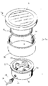
Fig. 6 shows a container 3x in the unassembled state,
the said container essentially consisting of a container
part 3g and container part 3h. Two lamps 33 are arranged in
the container part 3h. The container part 3g is conically
tapered toward its opening line la. Along the opening line
la, the container part 3g has a collar-like projection 8
which can be made to engage a diametrically opposite
projection 8 on the container part 3h. Container part 3g
and container part 3h are connected by means of shrink
sleeve 2b, which is coated on its inside with a hotmelt
adhesive 4a. The container part 3g has, at its upper end, a
light orifice 13,
. . :j!
`,:' j '
~t~_ :
&
through which the light from lamps 33 can pass into the
open. The light orifice is covered with a translucent or
transparent glass or plastic cover, which is not shown. A
ligh~ing unit of this type, or container 3x, can be used for
street lights, swimming pool lights or airfield lights, etc.
and is distinguished by outstanding tightness and rapid
assembly. The power supply is via a cable 34 and a cable
duct 15, which is in the form of a T nut and can be screwed
tightly into an orifice 14 of the container part 3h.
Inside, the container part 3h also contains a strongly
hygrophilic substance 16. On the one hand, this keeps the
air inside the container 3x dry while on the other hand it
is possible to inspect the hygrophilic substance visually
through the light orifice 13 and to determine whether or not
it has changed color due to the action of moisture. A very
discolored hygrophilic substance 16 would indicate that the
closure system had developed a leak.
The invention is in no way restricted by the Figures
shown. A closure system according to the invention can also
be provided in a very simple manner for angular containers
or containers or other shapes, or container parts.
It would also be possible to provide an additional O-
ring as a seal on the end face of the opening line and/or to
design the walls of the container parts to overlap one
another.