Language selection

Search

Patent 1316415 Summary

Third-party information liability

Some of the information on this Web page has been provided by external sources. The Government of Canada is not responsible for the accuracy, reliability or currency of the information supplied by external sources. Users wishing to rely upon this information should consult directly with the source of the information. Content provided by external sources is not subject to official languages, privacy and accessibility requirements.

Claims and Abstract availability

Any discrepancies in the text and image of the Claims and Abstract are due to differing posting times. Text of the Claims and Abstract are posted:

  • At the time the application is open to public inspection;
  • At the time of issue of the patent (grant).
(12) Patent: (11) CA 1316415
(21) Application Number: 1316415
(54) English Title: MOTOR-DRIVEN CHAIN SAW HAVING AN ARRANGEMENT FOR PREHEATING FRESH INTAKE AIR
(54) French Title: SCIE A CHAINE A MOTEUR MUNIE D'UN DISPOSITIF DE PRECHAUFFAGE DE L'AIR FRAIS D'ADMISSION
Status: Expired and beyond the Period of Reversal
Bibliographic Data
(51) International Patent Classification (IPC):
  • F02M 31/06 (2006.01)
  • B27B 17/00 (2006.01)
  • F02M 31/04 (2006.01)
  • F02M 31/093 (2006.01)
(72) Inventors :
  • FISCHER, HARTMUT (Germany)
(73) Owners :
  • FIRMA ANDREAS STIHL
(71) Applicants :
  • FIRMA ANDREAS STIHL (Germany)
(74) Agent: SMART & BIGGAR LP
(74) Associate agent:
(45) Issued: 1993-04-20
(22) Filed Date: 1988-09-02
Availability of licence: N/A
Dedicated to the Public: N/A
(25) Language of filing: English

Patent Cooperation Treaty (PCT): No

(30) Application Priority Data:
Application No. Country/Territory Date
P 37 29 814.3 (Germany) 1987-09-05

Abstracts

English Abstract


Abstract of the Disclosure
The invention is directed to an arrangement for heating
the intake air of the carburetor of the engine of a handheld
portable tool such as a chain saw. The fresh air entering the
air intake line is quickly and adequately heated and directed
to the carburetor as intake air without the danger of this
intake air becoming entrained with dirt particles. In the
arrangement according to the invention, the handheld portable
tool can be operated at low temperatures without disturbances
in the carburetor system such as freezing of the throttle flap
or the main nozzle. The air intake line is lead through the
muffler which is configured as a collection chamber for the
exhaust gas. The heat of the hot exhaust gases passing
through the muffler is transferred to the fresh air entering
and passing through the intake line.


Claims

Note: Claims are shown in the official language in which they were submitted.

23968-354
THE EMBODIMENTS OF THE INVENTION IN WHICH AN EXCLUSIVE
PROPERTY OR PRIVILEGE IS CLAIMED ARE DEFINED AS FOLLOWS:
1. A handheld portable power chain saw, comprising:
a housing;
an internal combustion engine mounted in said housing;
said engine including a combustion chamber wherein
exhaust gases are developed during operation of the engine;
a muffler mounted on the engine and defining an exhaust
gas collecting chamber;
passage means interconnecting said combustion chamber
and said exhaust gas collecting chamber for conducting said
exhaust gases into the latter;
an intake air collecting chamber mounted on said engine,
and a carburetor located therein for supplying a mixture of fuel
and air to said combustion chamber;
an air intake conduit extending through said exhaust gas
collecting chamber and connected at one end to said intake air
collecting chamber for conducting preheated air thereto; and
said air intake collecting chamber including an
ancillary air inlet for ambient air, whereby preheated and
unheated air may be mixed in said air intake collecting chamber.
2. A handheld portable chain saw according to claim 1,
wherein said carburetor has an air intake opening, and an air
filter is operatively arranged in advance of said air intake
opening.

23968-354
3. A handheld portable chain saw according to claim 2,
wherein a first segment of said air intake conduit is disposed
within said exhaust gas collecting chamber and has an outer sur-
face exposed to hot exhaust gases, and a second segment of said
air intake conduit extends from said exhaust gas collecting cham-
ber to said air intake collection chamber to define a preheated
air inlet thereto.
4. A handheld portable chain saw according to claim 3,
comprising temperature-dependent control means for controlling the
cross section of said preheated air inlet to said intake air col-
lecting chamber.
5. A handheld portable chain saw according to claim 4
wherein said temperature-dependent control means also controls the
cross-section of said ancillary air inlet.
6. A handheld portable chain saw according to claim 1, 2,
3, 4 or 5 wherein the external surface of said air intake conduit
within said exhaust gas collecting chamber is enlarged whereby to
increase the heat transferred from hot exhaust gases within said
exhaust gas collecting chamber to air passing through said air
intake conduit.
7. A handheld portable chain saw according to claim 6,
wherein said enlarged external surface of said air intake conduit
- 7 -

23968-354
comprises a plurality of lamella disposed thereon and projecting
therefrom.
8. A handheld portable chain saw according to claim 3, 4, 5
or 7 wherein said second segment of said air intake conduit is
provided with a heat insulating jacket.
9. A handheld portable chain saw according to claim 6,
wherein said second segment of said air intake conduit is provided
with a heat insulating jacket.
10. A handheld portable chain saw according to claim 1, 2,
3, 4, 5, 7 or 9 wherein said exhaust gas collecting chamber is
located adjacent said combustion chamber, and said passage means
is relatively short.
11. A handheld portable chain saw according to claim 1, 2,
3, 4, 5, 7 or 9 wherein the cross-section of said air inlet con-
duit is a minor fraction of the cross-section of said exhaust gas
collecting chamber.
12. A handheld portable chain saw according to claim 1, 2,
3, 4, 5, 7 or 9 wherein said exhaust gas collecting chamber is
provided with an exhaust gas outlet displaced in the axial direc-
tion of said air intake conduit, from said passage means, whereby
to prolong exposure of said air intake conduit to said exhaust
gases.
- 8 -

23968-354
13. A handheld portable chain saw according to claim 12
wherein the cross-section of the exhaust gas outlet is a minor
fraction of the cross-section of the opening of said passage into
the exhaust gas collecting chamber.
14. A method of introducing preheated intake air into the
internal combustion chamber of a handheld portable power chain saw
comprising the steps of introducing exhaust gases from the inter-
nal combustion chamber into an exhaust gas collecting chamber,
passing fresh intake air for said internal combustion engine
through said exhaust gas collecting chamber in heat exchanging
relationship to said exhaust gases, to preheat said intake air
conveying preheated intake air into a plenum chamber and then
through an air filter into a carburetor for said internal combus-
tion engine, and controlling the temperature of preheated intake
air in said plenum chamber by the introduction thereto of control-
led amounts of fresh ambient air.
- 9 -

Description

Note: Descriptions are shown in the official language in which they were submitted.


1 3 1 6 4 1
Motor DLiven (halll Saw ha~1ing an Ar~ra~y~ement for
_ __ _ ___ _ _ _ ._ _ _
Ireheat~ F~`resh Intake Air
Fie]d of the Invention
The invention relates to a portab1e handheld chain saw
driven by an internal combustion engine. The hot exhaust
gases discharged by the engine are utilized to heat the air
intake of the carburetor.
Background of the Invention
Handheld motor-driven chain saws of the kind referred to
above are used in the colder times of the year at low
temperatures such as in the wooded northern regions of
Scandinavia, North America and the Soviet Union. The use at
low temperatures placcs special requiremerlts on the internai
combustion engine driving the chain saw. The fresh air drawn
in by suction by the engine from the ambient air often leads
to disturbances in the carburetor system at low temperatures
and can lead especially to a freezing, for example, of the
throttle flap or the main nozzle.
To prevent the above-mentioned operational disturbances,
German Patent 3,604,166 discloses th.lt heated cooling air
occurring in the region of the outer surface of the cylinder
block of the engine can be conducted directly to the
carburetor. A fan wheel driven by the engine is provided for
cooling the outer surface of the cylinder bloc~ and directs a
targeted flow of cooling air over the cylinder block. A
component air current is branched off of the cooling air flow
heated in this manner and is directed to the carburetor. The
heated air directed to the carburetor is, however, not
adequately heated at low temperatures because the engine
operates at idle especially between the indlvidual cuts made

1 31 6~
with the ~aw chain and this idle operation causes the
rotational speed of the fan as well as the moved air flow to
become sharply reduced. For this reason, the heated cooling
air which is now presellt i5 not adequate to malntain the
carburetor system at a constant temperature. Furthermore,
dirt particles or the like become entrained because of the fan
and these dirt particles are directed with the component air
current to the carburetor system and the engine and can lead
to disturbances.
Summary of the Invention
It is an object of the invention to provide an
arrangement for heating the intake air of a carburetor by
means of which the fresh air is quickly and adequately heated
and directed to the carburetor as intake air without the
danger of dirt becoming entrained as described above.
According to a feature of the invention, an air intake
line leading -to the carburetor is provided which passes
through an exhaust gas collection chamber configured as a
muffler.
The hot exhaust gases discharged by the engine flow into
an exhaust gas collecting chamber configured as a muffler and
flow therethrough. These hot exhaust gases are utilized for
heating the fresh air in that the fresh air flow drawn in by
the engine by suction is conducted via the air intake line
through the muffler and thereby heated. The heated fresh air
flows via the air intake line into the plenum chamber
contained in the carburetor and from there passes through the
carburetor system to the engine.
A reduction of the motor capacity can occur if the fresh
air directed to the carburetor is heated too intensely. ~o

1 31 641 5
prevellt this condition, the heated fresh air ~lowing into the
plenum chamber is advantageously adjusted to the temperature
range which is optimal for operation by means of a
temperature-responsive control system in that cold air from
the ambient is admixed through an adjustable ancillary air
opening.
Brief Description of the Drawings
The invention will now be ~escribed with reference to the
drawings wherein:
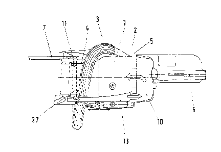
FIG. 1 is a plan view of a chain saw having a fresh air
preheating arrangement according to the invention; and,
FIG. 2 is a schematic diagram of the engine and the
carburetor system showing the fresh air preheating
arrangement.
Description of the Preferred Embodiments of the Invention
The engine 1 of the drive system of a chain saw includes
the cylinder block 2 with the exhaust gas line 3 and the
muffler 4 configured as an exhaust gas collector. The handle
part 6 is connected to the engine 1 across the so-called
vibration gap 5 by means of vibration-attenuating intermediate
members (not shown) in a manner known per se. The carburetor
housing 10 is mounted on the handle portion 6. The guide bar
guiding the saw chain 7 extends away from the engine 1 in a
direction opposite to that of -the handle portion 6 as shown
in FIG. 1.
Referring to FIG. 2, the fresh air current drawn in by
suction by the engine 1 flows through an inlet opening 11 into
an intake air line 27. The intake air line 27 passes through
the muffler 4 into which the hot exhaust gases are introduced
via the exhaust gas line 3 which extends from the cylinder

1316~
hlock 2. The exhaust gases vent to the ar~ ient via the
out-flow opening 15.
After leaving the muffl.er 4, the intake air line 27 leads
to the plenum chambeI- lO which contains a fresh-air
line ~13, 14) as well as an air filter 18 atld the
carburetor 19. The cross sec~ion of the out-fl.ow opening ~0
of the fresh air line ~13, 14) in the plenum chamber 10 is
changed by means of an adjusting device 21 via a
temperature-controlled regulator system 22 such that the fresh
air flows from the plenum chamber 10 to the air filter 18 and
so to the carburetor 19 at a constant temperature required for
the optimal operation of the engine 1 and the carburetor 19.
ln this way, a freezing of the throttle flap and of the main
nozzle is reliably prevented.
An ancillary air inlet opening 25 communicates directly
with the ambient air and the cold air required for maintaining
the ternperature in the plenum chamber 10 flows through this
inlet opening 25 with the cross section of the latter being
likewise changeable by the control system 22.
The line segment 13 of the fresh air ].ine (13, 14) is
provided with a heat-insulating jacket 26 to prevent heat loss
of the heated fresh air flowing in this segment 13 between the
muffler 4 and the plenum chamher 10.
The air intake line 27 coming through the muffler 4 can
be helical or serpentine in shape so as to extend its overall
length within the muffler to thereby ensure that the fresh air
flowing in through in].et opening 11 has the required heated
temperature. Another configuration for increasing the heat
transfer from the hot exhaust air of the muffler to the fresh
air coming into the air intake line 2~ is to provide the

1 3 1 6'~ i !
latter with a pl.urality of lamell.a 28' in order to provide a
larger surface 28 for transferrinc3 he.at to the fre~sh air.
1~. is onderstood -that the foregoing description is that
of the preferred embodimentc; of the inventiorl and that various
changes and modificati.ons may be made thereto ~ithout
departi.n~ from the spiri.t and scope of the invention as
defined in the appended claims.

Representative Drawing
A single figure which represents the drawing illustrating the invention.
Administrative Status

2024-08-01:As part of the Next Generation Patents (NGP) transition, the Canadian Patents Database (CPD) now contains a more detailed Event History, which replicates the Event Log of our new back-office solution.

Please note that "Inactive:" events refers to events no longer in use in our new back-office solution.

For a clearer understanding of the status of the application/patent presented on this page, the site Disclaimer , as well as the definitions for Patent , Event History , Maintenance Fee  and Payment History  should be consulted.

Event History

Description Date
Inactive: IPC from MCD 2006-03-11
Time Limit for Reversal Expired 1997-04-21
Inactive: Adhoc Request Documented 1997-04-20
Letter Sent 1996-04-22
Grant by Issuance 1993-04-20

Abandonment History

There is no abandonment history.

Owners on Record

Note: Records showing the ownership history in alphabetical order.

Current Owners on Record
FIRMA ANDREAS STIHL
Past Owners on Record
HARTMUT FISCHER
Past Owners that do not appear in the "Owners on Record" listing will appear in other documentation within the application.
Documents

To view selected files, please enter reCAPTCHA code :


To view images, click a link in the Document Description column. To download the documents, select one or more checkboxes in the first column and then click the "Download Selected in PDF format (Zip Archive)" or the "Download Selected as Single PDF" button.

List of published and non-published patent-specific documents on the CPD .

If you have any difficulty accessing content, you can call the Client Service Centre at 1-866-997-1936 or send them an e-mail at CIPO Client Service Centre.


Document
Description 
Date
(yyyy-mm-dd) 
Number of pages   Size of Image (KB) 
Cover Page 1993-11-11 1 14
Claims 1993-11-11 4 104
Abstract 1993-11-11 1 18
Drawings 1993-11-11 2 40
Descriptions 1993-11-11 5 147
Representative drawing 2002-02-15 1 10
Fees 1995-03-28 1 42
Correspondence 1993-01-27 1 33