Language selection

Search

Patent 1316521 Summary

Third-party information liability

Some of the information on this Web page has been provided by external sources. The Government of Canada is not responsible for the accuracy, reliability or currency of the information supplied by external sources. Users wishing to rely upon this information should consult directly with the source of the information. Content provided by external sources is not subject to official languages, privacy and accessibility requirements.

Claims and Abstract availability

Any discrepancies in the text and image of the Claims and Abstract are due to differing posting times. Text of the Claims and Abstract are posted:

  • At the time the application is open to public inspection;
  • At the time of issue of the patent (grant).
(12) Patent: (11) CA 1316521
(21) Application Number: 1316521
(54) English Title: COVER FOR WATER SUPPLY SERVICE BOX
(54) French Title: COUVERCLE POUR BOUCHE A CLE DE RESEAU D'AQUEDUC
Status: Expired and beyond the Period of Reversal
Bibliographic Data
(51) International Patent Classification (IPC):
  • F16K 35/00 (2006.01)
  • E03B 07/07 (2006.01)
  • E03B 09/10 (2006.01)
(72) Inventors :
  • RUEST, JACQUES R. (Canada)
  • RUEST, REGIS G. (Canada)
(73) Owners :
  • JACQUES R. RUEST
  • REGIS G. RUEST
(71) Applicants :
(74) Agent: LAVERY, DE BILLY, LLP
(74) Associate agent:
(45) Issued: 1993-04-20
(22) Filed Date: 1988-10-24
Availability of licence: Yes
Dedicated to the Public: N/A
(25) Language of filing: English

Patent Cooperation Treaty (PCT): No

(30) Application Priority Data: None

Abstracts

English Abstract


ABSTRACT OF THE DISCLOSURE:
A cover for protecting a water supply service box sur-
rounds the upper end of the box. The cover is a hollow sleeve provid-
ed with a flange peripherally projecting outside the sleeve. A remov-
able lid closes the upper end of the sleeve. The bottom of the sleeve
is partly opened to allow the passage of the top of the service box.
The sleeve is adapted to be supported by its flange which rests on
surrounding granular material. The upper edge of the sleeve remains
flush with the surface of the surrounding ground in spite of thaw and
frost.


Claims

Note: Claims are shown in the official language in which they were submitted.

6
CLAIMS:
1-. A protecting cover for a water supply service box,
said cover comprising a tubular sleeve partly opened at one end, for
allowing the passage of an upright pipe a removable plate fixed at
the other end for closing said sleeve, a flange member peripherally
extending outwardly around said sleeve; said flange being spaced from
both ends of said sleeve.
2-. A protecting cover as recited in claim 1, wherein
said one end is provided with an elongated opening for allowing the
passage of an upright pipe which is slightly tilted.
3-. A protecting cover as recited in claim 1, wherein
the sleeve is provided with two diametrically opposed shoulder mem-
bers fixed to said sleeve and extending inside the latter, said shoul-
der members being located adjacent said other end, said removable
plate adapted to sit on said shoulder members and means for tighten-
ing said plate on said shoulder members.
4-. A protecting cover as recited in claim 3, wherein
said tightening means comprises a cross-bar and a bolt pivotally
mounted through the center of said plate, said cross-bar adapted to
extend inside said sleeve below said shoulder, whereby the tightening
of the bolt secures the plate to the sleeve.
5-. A protecting cover as recited in claim 1, wherein
the said flange member comprises a rigid peripheral belt and a lip
projecting outwardly from said belt, and means for fixing said flange
member to said sleeve.
6-. A protecting cover as recited in claim 5, wherein
said fixing means comprises a plurality of bolts threadedly engaged
in said belt for securing said flange member to said sleeve.

Description

Note: Descriptions are shown in the official language in which they were submitted.


-" ~3~52~
TITLE OF THE INVENTION:
COVER FOR WATER SUPPLY SERVICE BOX
BACKGROUND OF THE INVENTION:
Field of the invention:
The invention relates to a protecting cover for a servi-
ce box and more particularly for a water supply service box adjacent
the level of the ground.
Prior art:
It is the usual practice to install a control valve bet-
ween the municipal water supply pipes and each domestic water piping
system, The control valve which is located at about six to eight feet
below the surface of the ground can be reached by a tubular service
box which ends up, at the top, flush with the level of the ground.
Considering that the level of the ground varies in height relative to
the top of the service box, due to the earth settling or the freezing
and the thaw of the ground, to top end of the service box exceeds abo-
ve the surface of the ground. Such tubular projection hinders the pro-
per operation of lawnmowers and snow-ploughs.
SUMMARY OF THE INVENTION:
According to the invention, the service box ends up be-
low the level of the ground and is covered by a sleeve supported by
the surrounding ground. The sleeve is a tubular member partly opened
at its lower end for allowing the insertion of the top of service
box. The top end of the sleeve is provided with a removable plate for
tightly closing that end. A flange extends around the outer periphery
of the sleeve and is located along a section intermediate between
both ends for resting on the surrounding ground, the latter remaining
flush with the upper periphery a the sleeve.
~ ... 2
., ~

~3~2~
- 2
BRIEF DESCRIPTION OF THE DRAWINGS:
Figure 1: is a schematic cross-sectional view of a co-
ver according to the invention mounted over a service box,
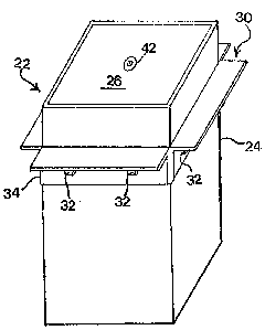
Figure 2: is a perspective view of the cover according
to the invention;
Figure 3: is a vertical sectional view of the cover
shown in figure 2, and
Figure 4: is a cross-sectional view of the cover along
line A-A of figure 3.
DETAILED DESCRIPTION OF THE DRAWINGS:
Figure 1 illustrates the general environment in which
the present invention is used. A service box 10 having a valve 12
located approximately between six and eight feet below the level of
the ground 14 is installed between a main water supply 16 coming from
the municipal water system and going through the pipe 18 towards a re-
sidence or a building. A long rod is used to operate the valve 12 by
introducing it through the top of the service box 10. In the past,
the top of the service box was flush with the level of the ground 14.
According to the invention, the top end 20 of the service box 10 is
made to recede below of the surface of the ground 14 ancL is surround-
ed by a cover 22. The installation of the cover 22 will be described
latter.
Figure 2 is a perspective view of the cover 22 which
comprises a tubular sleeve 24 having a square cross-section closed at
the top by a plate 26. The lower end of the sleeve 24 is partly clos-
ed and leaves an opening 28 sufficiently wide to allow the introduc-
tion of the top end 20 of the service box 10. A peripheral flange 30
is secured to the sleeve 24 by bolts 32 which are threadedly mounted
in the belt portion 34 of the flange 30 for tightening the latter on
:~ ... 3
~ ' ,
~'

the sleeve 24.The flange 30 may be permanently secured to the sleeve
24 but is preferably vertically adjustable by screwing and unscrewing
the bolt 32.
The lid 26 ;s intended to close the upper part of the
sleeve 24. In the embodiment shown in Eigures 3 and 4, a pair of brac-
kets 36, located in diametrically opposed directions are welded insi-
de the sleeve 24 adjacent the upper edge of the latter. A plate 38
which closes completely the inner periphery of the sleeve 24 rest on
the upper part of the brackets 36 which act as shoulder members. The
lid 26 is held to the sleeve 24 by a pivoting blade or cross-bar 40
rotatably suspended from the plate 38 by a bolt 42 and held by ~he
nut 44. The lid 26 is put in position over the brackets 36 when the
blade 40 does not overlap them. The blade 40 is then rotated to span
over both brackets 36. The bolt 42 is then tightened to squeeæe the
brackets 36 between the plate 38 and the blade 40. A stopper 45 is
welded to the plate 38 to stop the blade 40 from rotating when the
bolt 42 is unscrewed for releasing the plate 38. When the blade 40
abuts against the stopper 45, it is out of the way of the brackets
36.
The lower part of the sleeve 24 is partly closed with
spaced plates 46 providing an elongated opening 28. The si7e of the
opening 28 is sufficiently wide to allow the passage of the pipe 20
therethrough. The length of the opening 28 is foreseen in case the pi-
pe 20 is not perfectly vertical, that is, in the case it is slightly
tilted relative to the level of the ground.
In general, the sleeve 24 is six inches square in cross-
section with a height of about 12 inches. The flanges 30 as illus-
trated in the drawings are right angular brackets having dimensions
.

~ 3 ~
of two inches by two inches by six inches. The bolts 32 have a diame-
ter of 3/8 of an inch. If the sleeve 24 has a thickness of 1/4 of an
inch, the blade 38 has a dimension of 5 1/2 by 5 1/2 inches and a
thickness of 3/16 of an inch. The blade 40 is one inch wide and 5 in-
ches in length with a thickness of 1/4 of an inch. The brackets 36
are orthogonally shaped with dimensions of 1 inch x 1 inch x 2 1/2
inches. These brackets 36 are preferably welded inside ~he sleeve 24
at a level so that the plate 38 is flush with the upper edge of the
sleeve 24. The lower end of the sleeve 24 is partly closed with two
lateral parallel plates 46 having an 1 1/2 inch in width to leave an
elongated opening of about three inches wide. The elongation of the
opening allows the cover 22 to rest on the ground having a slope up
to 20 degrees relative to the horizon while the pipe 10 is vertical.
The installation of the cover is made as follows: the
pipe 10 is usually set in a hole of about six feet deep having a dia-
meter of about 2 feet at the bottom and whidening towards the top.
This hole is filled with granular material such as stone screenings
up to about 12 inches from the level of the ground which is the
height of the cover 22. This material is compacted. The cover 22 is
then seated over the pipe 10 so that the spaced plates 46 rest on the
surface of the compacted material while the upper edges of the sleeve
24 will be approximately level with the surrounding ground 14. More
granular materiql is added and compacted so that the flanges 30 rest
firmly on the granular material. The granular material is further
compacted when it has reach the level of the flanges 30. A filling ma-
terial is afterwards added to reach the top level of the sleeve 24.
Such filling material may be earth topped with grass. The lid 26 is
then installed.

~31~2~
The top part 20 of the pipe 10 being below the level of
ground can expend without projecting above the level of the ground
and the cover 22 which rests on the surrounding ground by the flanges
30, will vertically move with the latter even if frost or rain causes
movement of the surrounding foundation.
.;

Representative Drawing
A single figure which represents the drawing illustrating the invention.
Administrative Status

2024-08-01:As part of the Next Generation Patents (NGP) transition, the Canadian Patents Database (CPD) now contains a more detailed Event History, which replicates the Event Log of our new back-office solution.

Please note that "Inactive:" events refers to events no longer in use in our new back-office solution.

For a clearer understanding of the status of the application/patent presented on this page, the site Disclaimer , as well as the definitions for Patent , Event History , Maintenance Fee  and Payment History  should be consulted.

Event History

Description Date
Inactive: IPC from MCD 2006-03-11
Inactive: Incomplete 2002-03-12
Time Limit for Reversal Expired 2001-04-20
Letter Sent 2000-04-20
Inactive: Adhoc Request Documented 1998-04-20
Letter Sent 1997-04-21
Grant by Issuance 1993-04-20

Abandonment History

There is no abandonment history.

Fee History

Fee Type Anniversary Year Due Date Paid Date
MF (category 1, 5th anniv.) - small 1998-04-20 1998-04-20
MF (category 1, 6th anniv.) - small 1999-04-20 1999-04-19
Owners on Record

Note: Records showing the ownership history in alphabetical order.

Current Owners on Record
JACQUES R. RUEST
REGIS G. RUEST
Past Owners on Record
None
Past Owners that do not appear in the "Owners on Record" listing will appear in other documentation within the application.
Documents

To view selected files, please enter reCAPTCHA code :


To view images, click a link in the Document Description column (Temporarily unavailable). To download the documents, select one or more checkboxes in the first column and then click the "Download Selected in PDF format (Zip Archive)" or the "Download Selected as Single PDF" button.

List of published and non-published patent-specific documents on the CPD .

If you have any difficulty accessing content, you can call the Client Service Centre at 1-866-997-1936 or send them an e-mail at CIPO Client Service Centre.

({010=All Documents, 020=As Filed, 030=As Open to Public Inspection, 040=At Issuance, 050=Examination, 060=Incoming Correspondence, 070=Miscellaneous, 080=Outgoing Correspondence, 090=Payment})


Document
Description 
Date
(yyyy-mm-dd) 
Number of pages   Size of Image (KB) 
Abstract 1993-11-10 1 12
Claims 1993-11-10 1 30
Drawings 1993-11-10 1 34
Descriptions 1993-11-10 5 131
Representative drawing 2001-07-31 1 7
Maintenance Fee Notice 2000-05-22 1 178
Fees 1998-04-19 1 48
Fees 1999-04-18 1 42
Fees 1997-03-31 1 44
Fees 1995-04-19 1 29
Fees 1996-04-18 1 31
Correspondence 1993-01-25 1 32
Correspondence 1992-02-03 1 42
Correspondence 1991-12-15 1 22