Note: Descriptions are shown in the official language in which they were submitted.
- 1 - 1 3 ~ S ~ ~ ~
IIYDR~ULIC SHOCK ABSORBER WIT~ PR:E-LOADED VALVE FOR
I~INEAR VARIATION CHARACTERISTICS OF DA~IPING F~RCE
BACKGROUND OF THl~ INVENTION
Field of the Invention
The present invention relates generally to a hydraulic
shock absorber, suitable for use in an automotive suspension system.
More specifically, the invention relates to a shock absorber having
an improved piston stroke speed dependent damping characteristics.
Description of the Background Art
In general, hydraulic shock absorber generates damping
force determined by pressure difference across a flow restriction
valve structure. As will be appreciated, the pressure difference is
variable depending upon magnitude of flow restriction at the flow
restriction valve structure and working fluid flow rate. Working
fluid flow rate is determined by magnitude and speed of piston
stroke.
When the shock absorber employing constant orifice, is
used, the damping force varies at a rate substantially proportional
to two power of the piston stroke speed. Therefore, the damping
~` force tends to become insufficient at relatively low piston stroke
speed range so as not to generate suffioient damping force for
successfully damping relative displacement of a vehicular body and
a road wheel.
In order to improve this, two stage disc valve strategy
has been proposed for generating damping force for relatively low
speed piston stoke by a first stage valve and for higher speed
piston stroke by a second stage vale. Such two stage disc valve
strategy has been proposed in German Patent 833 574, for example.
The proposed shock absorber has the first stage and second stage
disc valves arranged in tandem fashion. The first stage disc valve
is principally active for generating damping force at relatively low
piston stroke speed range. On the other hand, the second stage disc
valve is principally active for generating damping force at higher
piston stroke speed range. Therefore, combining the first and
second stage disc valves, improved piston stroke speed dependent
- 2- ~3~
damping characteristics can be obtalned. Namely, In the
aforementioned German Patent, the damplng force varies at a rate
substantlally proportional to two over three (2/3) power of the
piston stroke speed.
On the other hand, in view of ease of tuning of
automotlve suspension system for achieving both of vehloular ridlng
comfort and driving stability, it is desirable to provide a shock
absorber having damping characteristics llnearly propot tlonal to the
piston stroke speed. In vlew of this requirement, the conventlonally
proposed shock absorbers are not satisfactory.
SUMMARY OF TllE INVENTION
Therefore, it Is an object of the present Invention to
provide a shock absorber which can provlde substantially linear
damplng characteristics in relation to plston stroke speed.
Another object of the invention Is to provlde a shock
absorber havlng a pre-loaded valve member for providing higher
rellef polnt for providing llnear varlatlon characterlstlos of damplng
force.
According to one aspect of the inventlon, a hydraullc
shock absorber comprises:
a hollow cylinder filled with a worklng fluid;
a piston thrustingly disposed within the interior space of
the cylinder for deflning first and second fluid chambers;
.
~ _ .
t
:. . ' ` ;; .
: . ""''`' :
_ 3 _ 1 3 ~ 6 ~ ~
a fluid communication means for establishing fluid
communication between the first and second chambers;
a flow restrictive first valve means associated with the
fluid communication means for generating a first damping force in
S response to piston stroke in one direction, the f irst valve means
generating the first damping force according to a first variation
characteristics when the piston stroke speed is lower than a first
criterion and according to a second variation characteristics when
the piston stroke speed becomes in excess of the first criterion;
a flow restrictive second valve means associated with the
fluid communication means and arranged in series with the first
valve means, for generating a second damping force in response to
piston stroke in the one direction, the second valve means
generating the second damping force according to a third variation
15 characteristics when the piston stroke is lower than a second
criterion and according to a fourth variation characteristics when
the piston stroke speed becomes in excess of the second criterion;
and
means for pre-loading the second valve means for
20 adjusting the second criterion for setting a transition point between
the third and fourth variation characteristics.
The first criterion may be set at lower piston stroke
speed than the second criterion. The first variation characteristics
may have greater gradient than that of the second variation
25 characteristics in the piston stroke speed range lower than the irst
criterion, and the third variation characteristics has smaller
gradient than that of the fourth varying characteristics in the piston
speed range lower than the second criterion.
In the preferred construction, the pre-loading means
30 comprises seat surface offset from the orientation perpendicular to
an axis of the shock absorber for forcingly bend the second valve
means for exerting pre-load. Alternatively, the pre-loading means
comprises seat surface offset from the orientation perpendicular to
an axis of the shock absorber and the second valve means is
35 provided spring force toward the seat surface for self-induoing
pre-load. In the former case, the pre-loading means causes
.
- .
:, .. ' ~
. ' '"'`" ' ' ' . ~ .
6~
deformation of the second valve means in a direction away from
the first valve means for exerting pre-load. In the later case, the
pre-loading means causes deformation of the second valve for
pre-loading, and the second valve means as seated on the seat
S surface serving as means for restricting deformation of the first
valve means.
The second valve means may be provided greater
external diameter than the diameter of an outer circumferential
edge of a seat surface, on which the second valve means is seated
lO while the piston stroke speed is lower than the second criterion.
In the preferred construction, the first valve means
comprises a first window opening defined on the the piston and
communicated with the fluid path, the window opening being
surrounded by a first land having a first surface, and a first
15 resilient valve means resiliently biased toward the surface for
normally establishing sealing contact with the first surface and
responsive to fluid flow in a first flow direction generated by the
piston stroke in the one stroke direction for forming a first flow
restrictive path for fluid communication from the first window
20 opening and one of the first and second fluid chambers for
generating the first damping force, and a second window opening
formed on the piston in fluid communication with the first window
opening, the second window opening being defined by a second land
with a second surface, and a second resilient valve means
25 resiliently biased toward ~ the second surface for normally
establishing sealing contact with the second surface and responsive
to fluid flow in a first flow direction generated by the piston
stroke in the one stroke direction for forming a second flow
restrictive path for fluid communication between the first and
30 second window openings for generating the second damping force.
Preferably, the shock absorber further comprises third
and fourth valve means provided for generating damping force in
response to a fluid flow in a second direction opposite to the first
direction, the third and fourth valve means being arranged in series
35 and being so designed as to establish essentially linear variation
characteristics of damping force depending upon piston stroke speed.
.... .
_ 5 - ~.3~
In such case the thlrd valve means may be responslve to piston
stroke for generating third damplng force varlable according to a
flrst variatlon characterlstics In relation to variation of the piston
stroke speed in a piston stroke speed range lower than a thlrd
criterion and accordlng to a second varlation characteristics when
the piston stroke speed is in excess of the thlrd criterion. and the
fourth valve means may be responsive to the plston stroke for
generating fourth damping force variation according to a third
variation characteristics in relatlon to variation of the piston stroke
speed when the piston stroke speed is lower than a fourth criterlon
and according to a fourth variation characteristics when the piston
stroke speed is in excess of the fourth criterlon thlrd valve means
comprises a third window opening defined on the the plston and
c~mmunicated with the fluid path the window open~ng belng
surrounded ~y a third land having a thlrd surface and n third
resilient valve means resiliently biased toward the surface for
normally establishing sealing contact with the third surface and
responsive to fluid flow in a second flow dlrection generated by the
piston stroke in the other stroke direction for forming R third flow
restrictive path for fluid communication from the third window
opening and one of the first and second fluld chambers for
generating the third damping force and a second window opening
formed on the piston In fluid communication wlth the thlrd wlndow
openlng the fourth wlndow opening being deflned by a fourth land
wlth a fourth surface and a fourth resilient valve means reslliently
blased toward the fourth surface for normally establishing sealing
contact with the fourth surface and responsive to fluld flow In a
second flow direction generated by the plston stroke in the the
other stroke direction for forming a fourth flow restrlctive path for
fluid communication between the first and fourth window openings
for generating the fourth damping force.
5~ ~ 3 ~
According to the present invention there is
provided a hydraulic shock absorber comprising:
a hollow cylinder -~illed with a working ~luid;
a piston thrustingly disposed within the interior
space of said cylinder for de~ining first and second fluid
chamber;
-rluid communication means for establishing fluid
communication between said first and second chamber;
flow restrictive ~irst valve means associated with
said fluid communication means for generating a first
damping force ln response to piston stroke in one direction,
said first valve means generating said first damping force
` according to a -first variation characteristic when the
piston stroke speed is lower than a first criterion and
according to a second variation characteristic when the
piston stroke speed becomes in excess of said first
criterion;
flow restrictive second valve means associated
with said fluid communication means and arranged in series
with said ~irst valve means, ~or generating a second damping
force in response to piston stroke in said one direction,
said second valve means generating said second damping force
according to a third variation characteristic when the
piston stroke speed is lower than a second criterion and
according to a fourth variation characteristic when the
piston stroke speed becomes in excess of said second
criterion; and
means for pre-loading said second valve means for
: 30 adJusting said second crlterion for setting a transition
: point between said third and fourth variation
characterlstics, said pre-louding means de~ormin~ a
circum~erential ed~e portlon o~ said second valve means.
.,,
~ ~ . ', ,
, ~ :: , : , .
, ' ''' ' ',
.
:1 3 ~
..
BRIEF DESCRIPTION OF T~l~ DI~AWINGS
The present invention will be understood more fully from
the detailed description given herebelow and from the accompanying
drawings of the preferred embodiment of the invention, which,
however, should not be taken to limit the inventlon to the specific
,, _ .. . . _ .. _ . _ /
A
~ . . ,
:
1 3 ~
embodiment but are for explanation and understanding only.
In the drawings: ~
Fig. 1 is a section of the preferred embodiment of a
shock absorber according to the present invention;
Fig. 2 is an enlarged section of the major part of a
piston employed in the preferred embodiment of the shock absorber
of Fig. 1, which is the detail in the encircled portion A in Fig. l;
Fig. 3 is an enlarged section of the major part of a
bottom valve employed in the pref erred embodiment of the shock
absorber of Fig. 1, which illustrates detailed construction of the
encircled portion B in Fig. 1;
Figs. 4(~), 4(B) and 4(C) are graphs showing variation of
damping force relative to piston stroke speed, in which Fig. 4(A)
shows damping characteristics of a first stage disc valve relative to
the piston stroke speedl ~ig. 4(Bj shows damping characteristics of
a second stage disc valve relative to the piston stroke speed, and
Fig. 4(C) shows damping characteristics of flow restriction orifice;
.
Fig. 5 is a graph variation of damping force generated
by the shock absorber in relation to ~piston stroke speed;
~; -20 Fig. 6 is an enlarged section of a piston valYe assembly
in the modif ied embodiment of shock absorber according to the
present invention;
Fig. 7 is a graph showing damping characteristics of the
modified embodiment of the shock absorber in comparison with
damping characteristics of the c onventional shock absorbers;
~ig. 8 is a section of another~ embodiment of a shock
absorber according to the present invention;
Fig. 9 is an enlarged section of the major part of a
piston employed in the another embodiment of the shock absorber of
Fig. 8, which is the detail in the encircled portion A in Fig. 8;
Fig. 10 is a further enlarged section of the major part
of a piston valYe assembly of Fig. 9, in which is shown
dimensional relationship of components in the piston valYe assembly;
and
. .;
:. . . .;
:
~ 3 ~
Fig. 11 is an enlarged section of the major part of a
bottom valve employed in the another embodiment of the shock
absorber of Fig. 8, which illustrates detailed construction of the
encircled portion B in Fig. 8.
S DES~:RIPTION OF THE PREFERRED EMBODIMENT
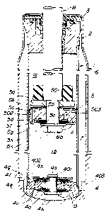
Referring now to the drawings, particularly to Fig. 1,
the preferred embodiment of a hydraulic shock absorber, according
to the present invention, employs a double action structure
including an inner and outer cylinders 1 and 6. The top end of the
10 inner cylinder 1 is closed a guide member 2 and a seal member 3.
On the other hand, a bottom fitting assembly 4. Therefore, the
inner cylinder 1 defines an enclosed space filled with a working
. fluid. A piston assembly 5 is disposed within the enclosed space of
the inner cylinder 1 for thrusting movement therein and dividing the
15 enclosed space upper and low fluid chambers la and lb. On the
other hand, an annular reservoir chamber 7 filled with a working
fluid and working gas. -
The piston assembly 5 is mounted on the lower end of apiston rod 8 for thrusting movement therewith. The piston assembly
20 5 comprises a retainer 5a, a check plate Sb, a piston body 5c, a
first stage disc valve 5d, a washer 5e, a stopper plate 5f, a second
stage disc valve 5g, a washer 5h, a collar 5j, a spring seat 5k and
an assist spring 5m. Theses components are gathered at the smaller
diameter section 8b of the piston rod 8 and firmly secured to the
25 lower end by means of a fastening nut 5n which engages with a
threaded portion 8a of the small diameter section 8b of the piston
rod.
The piston body 5c def ines a through opening 502
oriented in the vicinity of the outer circumference thereof. The
30 through opening 502 may be hereafter referred to as "outer axial
opening". The piston body 5c also defines a through opening 503
oriented at an orientation close to a center opening 501 which
receives the small diameter section 8b of the piston rod 8. The
opening 503 will be hereafter referred to as "inner axial opening".
35 The upper end of the outer axial opening 502 is openably closed by
means of the check plate 5b. The check plate 5b blocks fluid flow
~ 3 ~
-- 8 --
from the upper fluid chamber la to the lower fluid chamber lb.
On the other hand, the check plate 5b is the fluid pressure in the
lower fluid chamber lb for permitting fluid flow through a gap
formed by deformation of the check plate from the lower fluid
5 chamber lb to the upper fluid chamber la.
On the other hand, as shown in Fig. 2, thè lower end of
the inner axial opening 503 is closed by the first and second stage
disc valves 5d and 5g. The first stage disc valve 5d is normally
seated on inner and outer seat surfaces 504 and 505
10 Cross-sectionally essentially semi-circular groove 507 is formed
adjacent the outer side seat surf ace 505. On the other hand, the
second stage disc valve 5g is seated on annular seat surf ace 506
which is formed along the outer circumference of the piston body
5c~ As can be seen from ~ig. 2, the first stage disc valve 5d
15 opposes the stopper plate 5f via the washer 5e. The
circumferential edge of the washer 5e defines support of
deformation of the first stage disc valve 5d. Magnitude of
deformation of the first disc valve Sd is limited by the stopper
plate 5f so that - the maximum deformation magnitude corresponds
20 to the thickness of the washer 5e. Once the circumferential edge
of the first disc valve 5d comes into contact with the stopper
plate, the intermediate portion ~of the first disc valve is gradually
deformed with progressively increased reaction force. ~
It should be appreciated ~ that, in the shown embodlment,
25 the first disc valve is provided relatively low spring constant so
that it may react on substantially small pressure difference between
the upper and lower fluid chambers la and lb. Therefore, even at
very low piston speed, the first disc valve Sd is deformed for
permitting corresponding flow rate of fluid flow for generating
30 damping force.
As seen from Fig. 2, the contact point 512 between the
second stage disc valve 5g and the annular seat surface 506 is
oriented at downwardly offset position in a magnitude Hl from the
orientation of the lower surface of the stopper pIate. On the
35 other hand, one or more constant orifices 508 are formed between
the second disc valve 5g and the seat surface 507 to permit
-. , . .. ', : ,: :
. .
.
., ;. ~ , . ..-: ': , .
- , . .
13~6~
g
minimum fluid flow. The constant orifice 508 may not be effective
at initial stage of the piston stroke until the first disc valve 5d is
deformed at a given magnitude to establish a given fluld flow.
The second disc valve 5g is provided greater spring
5 constant so as to provide greater resistance in deformation. The
spring coefficient of the second disc valve 5g is so determined as
to achieve linear variation of the damping force depending upon
the piston stroke magnitude and piston stroke speed.
The bottom fitting is provided a bottom valve assembly.
10 The bottom valve assembly comprlses outer and inner axial openings
402 and 403 defined through a body 4f of the fitting. The valve
assembly also comprises a washer 4b, a second stage disc valve 4c,
a washer 4d, a first stage disc valve 4e, a checl~ plate 4g, a a
check sprlng 4h and a collar. These components are gathered and
15 secured onto the fitting body 4f by means of fastenlng bolt 4a, for
whlch f astenlng nut 4k Is engaged. The upper end of the outer
axial opening 402 is operably closed ~by the check plate 4g by
seatlng onto seat surfaces deflned on the upper surface of the
fitting. Therefore, the fluid flow from the lower fluid chamber lb
20 to the reservoir chamber 7 is blocked and the fluid flow in the
opposite direction is permitted.
On the other hand, as shown In Fig. 3, the flrst dlsc
valve 4e openable closes the lower end of the inner axial openlng
403 by seating onto the seat surfaces 404 and 405 respectively
25 defined on the center boss sectlon and an annular land extending
clrcumferentlally at the radially outer side of the inne r axial
opening 403. An essentially seml-clrcular groove 407 Is formed
Immediate outside of the seat surface 405 and extends therealong.
The second dlsc valve 4c is seated onto a seat surf ace 406 at the
30 circumferentlal edge portlon.
As seen from Fig. 3, the contact polnt 412 between the
second stage disc valve 4c and the annular seat surface 406 is
oriented at downwardly offset position in a magnitude H2 from the
orientation of the lower surface of the stopper plate. One or more
35 constant orifices 408 is formed through the seat surface ~06 so as
to provide constant fluid flow in minirnum flow rate.
.,
,
:.
.
.
.
1 3 ~
- 10 -
As can be seen from Figs. 2 and 3, the bottom valve
assembly operates substantially in the same manner to that valve
assembly in the piston.
The operation of the shown embodiment of the shock
5 absorber will be discussed herebelow with respect to respective of
rebounding and bounding mode operations.
In the piston bounding mode stroke, the piston assembly
5 moves upwardly relative to the inner cylinder 1 for compressing
the volume of the upper fluid chamber la and expanding the volume
10 of the lower fluid chamber lb. By variation of volumes, a fluid
pressure difference is generated so that the fluid pressure in the
upper fluid chamber la becomes higher than the lower fluid
chamber lb~ Therefore, fluid flow from the upper fluid chamber la
to the lower fluid chamber lb is generated. Furthermore, because
lS of lowering of the fluid pressure in the lower fluid chamber lb, the
fluid pressure in the reservoir chamber 7 becomes higher than that
in the lower fluid chamber lb for causing fluid flow through the
bottom valve assembly. Therefore, working fluid in the upper fluid
chamber la and the reservoir chamber 7 flows into the lower fluid
20 chamber lb until the pressure balance between the upper and lower
fluid chambers and the reservoir chamber is established.
During the piston rebounding stroke, the working fluid in
the upper fluid chamber la flows into the inner axial opening 503.
Against the fluid flow, the first and second~ disc valves Sd and 5g
25 are active for providing fluid flow restriction and thus generating
damping force. Figs. ~(A) and 4(B) show damping characteristics of
respective of individual first and second stage disc valves 5d and
5g, in relation to the piston stroke speed. As can be seen from
Fig. 4(A), the first stage disc valve Sd is normally in closed
30 position for completely blocking fluid flow from the upper fluid
chamber la to the lower fluid chamber lb. The first stage disc
valve 5d is responsive to even relatively small pressure difference
to cause deformation for forming fluid flow orifice between the
seat surface 506 to permit limited amount of fluid flow from the
35 upper fluid chamber to the lower fluid chamber. As a result,
damping force is created as shown in Fig. ~(A). As can be seen,
.' '' ' '
,
';
,
~ 3~$~
at the initial stage of the piston stroke, the damping force is
increased in proportion to the piston stroke speed S in a rate of two
over three power of the piston speed (S(2/3)) (as in the range (1)
of Fig. 4(A~. The damping force generated by the first stage disc
5 valve is much greater than that generated by the constant orifice
in the prior art. On the other hand, in the low piston stroke speed
range, the second stage disc valve 5g is held seated on the
associated seat surface 506. Therefore, during low piston stroke
speed range, only the constant orifices 508 are active for
10 generating damping force. Therefore, as shown in the region (2) in
Fig. 4(B), the second stage disc valve 5g generates damping force
varying at a rate proportion to two power of the piston stroke
speed (S2).
When the circumferential edge of the first disc valve 5d
15 comes into contact with the stopper plate Sf, the spring constant
of the first disc valve becomes greater to vary the variation rate
of the damping force to be greater rate. In ~ig. 4(A~, the point
where the variation characteristics of the darnping force is changed,
corresponds to the magnitude of the pressure difference at which
20 the circumferential edge of the first disc valve comes into contact
with stopper plate 5f. When the pressure difference is grown
greater than the point above the relief point of the flrst stage disc
valve 5d, the flow restriction path formed by the first stage disc
valve 5d becomes substantially constant. As a result, the variation
25 characteristics of damping force relative to variation of the piston
stroke speed becomes substantially corresponding to that of the
constant orifice as shown in the region (3) of Fig. 4(A).
As set forth, the conventional constant orifice provides
variation characteristics of the pressure difference proportional to
30 two power of the fluid flow rate Q (Q2) ~)n the other hand, the
variation characteristics of the pressure difference in the first disc
valve of the invention is proportional to two over three power of
the fluid flow rate (Q(2/3)). As seen, in the shown embodiment,
relatively large damping force is generated at very initial stage of
35 the piston stroke.
On the other hand, l~ig. 4(B) shows the variation
..
1 3 1 ~
- 12 -
characteristics of the damping force versus the piston sttoke speed
at the second stage disc valve 5g. As set forth above, the second
stage disc valve 5g is held closed position at the low piston stroke
range. At this condition, the working fluid flows through the
5 constant orifices 508. In the low piston stroke speed range, since
the only constant orifice 508 is effective for generating the
damping force, the variation characteristics of the damping force in
the low piston stroke range becomes substantially proportional to
two posver of the piston stroke speed S (S2) as shown in region (2)
10 of Fig. 4(B).
When the piston stroke speed is increased to increase
pressure difference, greater force i5 exerted on the second stage
disc valve 5g for causing the latter to deform for increasing the
fluid flo~N path area. The fluid pressure difference at which the
15 second stage disc valve starts to deform, is referred as relief point
p. As clear from ~ig. 4(B), the damping force increasing rate at
the second stage disc valve 5g is thus small in the low piston
stroke speed range . Af ter reaching the turning point p where the
second stage disc valve 5g starts to open, the variation
20 characteristics becomes substantially proportional to two over three
power of the piston speed as shown in the region (4) of ~ig. 4(B).
In addition to the above, the inner axial path 503 serves
as constant orifice for generating additional damping force. As can
be seen from ~ig. 4(C), since the path area of the inner axial path
25 503 is held constant, the variation characteristics to be generated
by this inner axial path 503 is substantially proportional to two
power of the piston stroke speed.
Therefore, by combination of the first stage and second
stage disc valves 5d and 5g, and the inner axial opening 503,
30 essentially linear variation characteristics as shown in Fig. 5 can be
provided. Such linear characteristics of the variation of the
damping force provided by the preferred embodiment of the shock
absorber is effective for obtaining better vehicular body attitude
stabilization capacity when the shock absorber is applied as a
35 component of the automotive suspension system, with satisf actorily
high response. Particularly, the invention is particularly effective
.
.
.
: .
,~ , .
- 13 ~
in damping relatively low speed piston stroke. Furthermore,
according to the shown embodiment, since the variation
characteristics of the damping force is essentially linear in the
shown embodiment, high vehicular driving stability can be obtained.
Furthermore, in order to enhance the damping
characteristics in the piston stroke speed, the relief point p of the
second stage disc valve 5g is to be risen. In order to set the
relief point p at higher point (higher pressure difference), it is
preferably to provide higher initial resiliency for the second stage
10 disc valve without changing spring coefficient thereof. For this,
the shown embodiment provides a predetermined magnitude of
pre-load for providing initial deformation of the second stage disc
valve 5g by shifting or offsetting the seat point between the seat
surf ace 506 and the second stage disc valve. By providing
15 pre-load, a resilient force of the second stage disc valve at the
initial position resisting against the deformation force exerted
thereonto by pressure difference between the upper and lower fluid
chamber, is increased. As a result, the relief point p becomes
higher as shown by broken line and point p', as shown in the region
20 (6) of Fig. 4tB)- Therefore, by adjusting the offset magnitude H1,
the relief point p can be set at a desired point. This can be
compared with the characteristics obtained from the conventional
construction as shown by the one-dotted line b of Fig. ~(B).
On the other hand, in the piston bounding stroke, the
25 piston strokes with compressing the lower fluid chamber lb to
generate fluid pressure difference between the upper and lower
fluid chambers and between the lower fluid chamber and the fluid
reservoir chamber. As a result, fluid flow toward the upper fluid
chamber la and toward the fluid reservoir chamber 7 from the
30 flower fluid chamber lb is generated. Then, the first and second
stage disc valves 4f and 4c becomes effective for generating
damping force varying according to generally linear characteristics
as set forth with respect to the valve assembly of the piston.
During this piston bounding stroke, the piston ring 11
35 and the seal ring 12 are effectively for assuring leak tight seal for
avoiding lowering of the damping force at the initial stage of the
- 14 - :L3~
piston stroke.
Similarly to the foregoing piston valve ~ssembly, by
adjusting offset magnitude H2, the relief point of the second stage
disc valve 4c can he adjusted for obtaining desired damping
5 characteristics. Therefore, desired damping characteristics can be
obtained for damping bounding piston stroke.
Fig. 6 shows a modification of the foregoing first
embodiment of the shock absorber according to the present
invention. As can be seen from Fig. 6, the shown embodiment is
10 constructed by neglecting the stopper plate for restricting
magnitude of deformation of the first stage disc valve 5d.
Therefore, in this embodiment, the second stage disc valve 2g
serves as stopper for restricting deformation magnitude of the first
st age disc valve.
According to the shown embodiment, in order to adjust
the deformation stroke Hl' of the first stage disc valve 5d, the
seating point 511 between the seat surf ace 506 and the second
stage disc valve 5g is offset upwardly in a magnitude H2'. By this
construction, in the medium piston stroke range in which the first
20 stage disc valve 5d is held in fully open position and the second
stage disc valve 5g is still held in closed position, greater rate of
variation of damping force in relation to the piston stroke speed
can be obtained. On the other hand, after starting deformation of
the second stage valve 5g, the first stage disc valve 5d is again
25 permitted to deform for lowering increasing rate of the damping
force. At the same time, since the second stage disc valve is
deformed, the damping characteristics at the second stage disc
valve becomes proportional to two over three (2/3) power of the
piston stroke speed. As a result, in the high piston stroke speed
30 range, variation rate of the damping force relative to the piston
stroke speed becomes smaller.
Therefore, the damping characteristics as shown by solid
line in Fig. 7 can be obtained. In ~ig. 7, the damping
characteristics obtained by the shown embodiment is compared with
35 the characteristics as shown by broken lines (1) and (2). The broken
line (1) shows damping characteristics of in the conventional disc
. .
!.
- 15 - ~ 3~
valve which is not limited the deformation magnitude. On the
other hand, the broken line (2) -shows example of damping
characteristics obtained by adjusting the axial opening flow path
area. In such case, though the greater variation rate of the
5 damping force can be obtained in the medium piston speed range, it
becomes possible to provide smaller damping force variation rate.
Therefore, improved piStOll stroke speed dependent damping
characteristics can be obtained in the shock absorber.
Figs. 8 through 11 shows another embodiment of the
10 shock absorber according to the present invention. In this
embodiment the first stage disc valve 5d and the stopper plate 5f
are formed to have an external diameter ~ which is greater than
the external diameter ~1 of the seat surface 505 so that the
circumferential edges extend from the outer circumferential edge of
15 the seat surface 505 in a magnitude of S3. Similarly, the first
stage disc valve 4e of the bottom valve is also provided greater
external diameter than that of the mating seat surface.
With this construction, the extra margin provided for
the first stage disc valve may compensate torelance in formation of
20 the seat surface or the first disc valve and thus assure seating
contact .
In addition, by providing semi-circular grooves 507 and
4~07 for the piston body 5c and the fitting body 4f, the stiffness at
inner and outer circumferential edges of the seat surface becomes
25 even in sintering process for providing higher cavitation resistance.
While the present invention has been disclosed in terms
of the preferred embodiment in order to facilitate better
understanding of the invention, it should be appreciated that the
invention can be embodied in various ways without departing from
30 the principle of the invention. Therefore, the invention should be
understood to include all possible embodiments and modifications to
the shown embodiments which can be embodied without departing
from the principle of the invention set out in the appended claims.